Sélection de la langue

Search

Sommaire du brevet 3008293 

Énoncé de désistement de responsabilité concernant l'information provenant de tiers

Une partie des informations de ce site Web a été fournie par des sources externes. Le gouvernement du Canada n'assume aucune responsabilité concernant la précision, l'actualité ou la fiabilité des informations fournies par les sources externes. Les utilisateurs qui désirent employer cette information devraient consulter directement la source des informations. Le contenu fourni par les sources externes n'est pas assujetti aux exigences sur les langues officielles, la protection des renseignements personnels et l'accessibilité.

Disponibilité de l'Abrégé et des Revendications

L'apparition de différences dans le texte et l'image des Revendications et de l'Abrégé dépend du moment auquel le document est publié. Les textes des Revendications et de l'Abrégé sont affichés :

  • lorsque la demande peut être examinée par le public;
  • lorsque le brevet est émis (délivrance).
(12) Demande de brevet: (11) CA 3008293
(54) Titre français: SUPPORT D'ACCESSOIRE DESTINE A UN VEHICULE
(54) Titre anglais: ACCESSORY MOUNT FOR A VEHICLE
Statut: Examen
Données bibliographiques
(51) Classification internationale des brevets (CIB):
  • B60R 09/00 (2006.01)
  • B60Q 01/26 (2006.01)
  • B60R 09/04 (2006.01)
(72) Inventeurs :
  • SCHELLENS, THOMAS E. (Etats-Unis d'Amérique)
(73) Titulaires :
  • THOMAS E. SCHELLENS
(71) Demandeurs :
  • THOMAS E. SCHELLENS (Etats-Unis d'Amérique)
(74) Agent: OSLER, HOSKIN & HARCOURT LLP
(74) Co-agent:
(45) Délivré:
(22) Date de dépôt: 2018-06-15
(41) Mise à la disponibilité du public: 2018-12-21
Requête d'examen: 2023-06-06
Licence disponible: S.O.
Cédé au domaine public: S.O.
(25) Langue des documents déposés: Anglais

Traité de coopération en matière de brevets (PCT): Non

(30) Données de priorité de la demande:
Numéro de la demande Pays / territoire Date
16/003,224 (Etats-Unis d'Amérique) 2018-06-08
62/522,775 (Etats-Unis d'Amérique) 2017-06-21

Abrégés

Abrégé anglais


An accessory mount mountable to a roof of a vehicle with
the use of an existing brake light opening. The accessory
mount has a horizontal mounting surface and a vertical
mounting surface. Accessories, such as lights, may be
mounted on the mounting surfaces. A shaped clamp is
placed through the existing brake light opening and when
rotates the horizontal mounting surface tightly against
the roof of the vehicle securely attaching the accessory
mount to the vehicle without the need for making any
additional holes in the vehicle.

Revendications

Note : Les revendications sont présentées dans la langue officielle dans laquelle elles ont été soumises.


What is claimed is:
1. An accessory mount for attaching to a vehicle
through an existing opening in the vehicle comprising:
a monolithic body having opposing body ends and a
first mounting surface forming a first plane and a second
mounting surface forming a second plane, the first plane
transverse to the second plane, the second mounting
surface having an opening formed therein;
a side plate attached to each of the opposing body
ends of said monolithic body;
a shaped bracket having opposing bracket ends, said
shaped bracket adapted to be inserted through the opening
in the second mounting surface and into the existing
opening in the vehicle, whereby the shaped bracket is
capable of being positioned to span the existing opening
in the vehicle; and
a fastener attached to said shaped bracket between
the opposing bracket ends,
whereby said shaped bracket is capable of being
inserted into the existing opening in the vehicle and
positioned so as to attach the accessory mount to the
vehicle with said fastener through the existing opening
in the vehicle.
12

2. The accessory mount for attaching to a vehicle
as in claim 1 wherein:
said shaped bracket comprises an upper foot
positioned adjacent to the horizontal mounting surface, a
body, and a lower foot positioned adjacent the horizontal
mounting surface.
3. The accessory mount for attaching to a vehicle
as in claim 2 further comprising:
a through hole placed in the body, said through hole
positioned closer to the lower foot than the upper foot
and adapted to receive said fastener.
4. The accessory mount for attaching to a vehicle
as in claim 3 further comprising:
a cushion placed on the upper foot.
5. An accessory mount for attaching to a roof of a
vehicle through an existing brake light opening in the
vehicle comprising:
a body having opposing body ends and a first
mounting surface forming a first plane and a second
mounting surface forming a second plane, the first plane
transverse to the second plane, the second mounting
surface having an opening formed therein positioned to
align with the existing brake light opening in the
13

vehicle, said body having a shape conforming to the roof
of the vehicle;
a side plate attached to each of the opposing body
ends of said body, each of said side plates having a
shape conforming to the roof of the vehicle;
a shaped bracket having opposing bracket ends, said
shaped bracket adapted to be inserted through the opening
in the second mounting surface and into the existing
brake light opening in the vehicle, whereby the shaped
bracket is capable of being positioned to span the
existing brake light opening in the vehicle and contact
the vehicle adjacent opposing ends of the existing brake
light opening; and
a fastener attached to said shaped bracket between
the opposing bracket ends,
whereby said shaped bracket is capable of being
inserted into the existing opening in the vehicle and
positioned so as to attach the accessory mount to the
vehicle with said fastener through the existing opening
in the vehicle.
6. The accessory mount for attaching to a roof of a
vehicle through an existing brake light opening in the
vehicle as in claim 5 wherein:
said shaped bracket comprises an upper foot
positioned adjacent to the horizontal mounting surface, a
14

body, and a lower foot positioned adjacent the horizontal
mounting surface.
7. The accessory mount for attaching to a roof of a
vehicle through an existing brake light opening in the
vehicle as in claim 6 further comprising:
a through hole placed in the body, said through hole
positioned closer to the lower foot than the upper foot
and adapted to receive said fastener.
8. The accessory mount for attaching to a roof of a
vehicle through an existing brake light opening in the
vehicle as in claim 7 further comprising:
a cushion placed on the upper foot.
9. The accessory mount for attaching to a roof of a
vehicle through an existing brake light opening in the
vehicle as in claim 6 wherein:
the body has a body longitudinal axis and the lower
foot has a lower foot longitudinal axis, wherein the
lower foot longitudinal axis traverses the body
longitudinal axis at an angle of substantially forty-five
degrees.

10. An accessory mount for attaching to a roof of a
vehicle through an existing brake light opening in the
vehicle comprising:
a body having opposing body ends and a first
mounting surface forming a first plane and a second
mounting surface forming a second plane, the first plane
transverse to the second plane, the second mounting
surface having an opening formed therein positioned to
align with the existing brake light opening in the
vehicle, said body having a shape conforming to the roof
of the vehicle;
a side plate attached to each of the opposing body
ends of said body, each of said side plates having a
shape conforming to the roof of the vehicle;
a cushion placed on said body and each of said side
plates on a surface adapted to be placed adjacent the
roof of the vehicle;
a shaped bracket having opposing bracket ends, said
shaped bracket comprising an upper clamp foot, a clamp
body, and a lower clamp foot having a toe, and a through
hole placed closer to the lower clamp foot than the upper
clamp foot, said shaped bracket adapted to be inserted
through the opening in the second mounting surface and
into the existing brake light opening in the vehicle,
wherein the shaped bracket is capable of being positioned
to span the existing brake light opening in the vehicle
16

and the upper clamp foot to contact the vehicle adjacent
an upper end of the existing brake light opening and the
toe of the lower clamp foot to contact the vehicle
adjacent a lower end of the existing brake light opening
opposite the upper end of the existing brake light
opening; and
a fastener placed through the second mounting
surface and attached to said shaped bracket at the
through hole between the opposing bracket ends, wherein
when the fastener is tightened drawing the second
mounting surface towards the vehicle the first mounting
surface is rotated towards the roof of the vehicle,
whereby said shaped bracket is capable of being
inserted into the existing opening in the vehicle and
positioned so as to attach the accessory mount to the
vehicle with said fastener through the existing opening
in the vehicle without accessing inside the vehicle or
making any additional openings or holes in the vehicle.
17

Description

Note : Les descriptions sont présentées dans la langue officielle dans laquelle elles ont été soumises.

ACCESSORY MOUNT FOR A VEHICLE
FIELD OF THE INVENTION
The present invention relates in general to in
accessory mount for a vehicle, and particularly to in
accessory mount attached to a vehicle using an existing
opening.
BACKGROUND OF THE INVENTION
It is often desirable to mount accessories to a
motor vehicle, such as a truck or sport utility vehicle,
SUV. While there are many attachments used to mount
accessories onto vehicles many often require modification
or drilling of additional holes or openings in the
vehicle. This often makes mounting of an accessory more
difficult and results in an opening left in the vehicle
upon removing the accessory. One mount addressing these
problems is disclosed in United States patent 9,162,628
issuing to Thomas Schellens on October 20, 2015. Therein
disclosed is a vehicle mounting platform that uses an
existing opening, such as a brake light opening, in a
vehicle for mounting a platform. While this vehicle
mounting platform has been successful, there is a need
for an improved vehicle mounting platform that is
1
CA 3008293 2018-06-15

efficiently manufactured and easily attached to the
vehicle with an existing opening in the vehicle.
SUMMARY OF THE INVENTION
The present invention is an accessory mount that has
a horizontal and vertical surface for mounting
accessories to a vehicle, and in particular the roof. The
accessory mount uses an existing opening in the vehicle
for attachment, and in particular a brake light opening.
The body of the accessory mount is a single piece having
multiple bends or folds. Side plates are used on each end
of the body and conform to the curvature of the roof of
the vehicle. A shaped clamp having an intermediate
fastener is placed within the existing opening,
positioned, and secured from the exterior of the vehicle.
Accordingly, it is an object of the present
invention to attach the accessory mount to an existing
opening of a vehicle.
It is an advantage of the present invention that it
is easy to install and securely held onto the vehicle.
It is another advantage of the present invention
that it is made with a minimum of parts and is easily
assembled.
2
CA 3008293 2018-06-15

It is yet another advantage of the present invention
that a shaped clamp causes the accessory mount to rotate
into a secure position during installation.
Is a feature of the present invention that the
shaped clamp is entirely held within the vehicle.
It is another feature of the present invention that
the shaped clamp has an upper foot, a body, and a lower
foot.
It is another feature of the present invention that
the body of the accessory mount is a single piece and
adapts to the shape of the vehicle.
It is yet another feature of the present invention
that the side plates conform to the shape of the vehicle.
It is yet another feature of the present invention
that the accessory mount has both a horizontal surface
and a vertical surface for mounting an accessory.
These and other, objects, advantages, and features
will become more readily apparent in view the following
detailed description.
BRIEF DESCRIPTION OF THE DRAWINGS
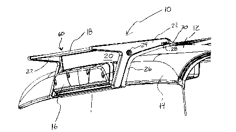
Fig. I is a perspective view schematically
illustrating the present invention attached to a vehicle.
Fig. 2 is a side elevational view illustrating the
present invention.
3
CA 3008293 2018-06-15

Fig. 3 is a perspective view illustrating an
interior portion of the present invention.
Fig. 4 is a perspective view illustrating an
exterior portion of the present invention.
Fig. 5 is a perspective exploded view schematically
illustrating the present invention from above.
Fig. 6 is a perspective exploded view schematically
illustrating the present invention from below.
Fig. 7 is a perspective close up view of a portion
of the present invention illustrating the structure of
the front seal in more detail.
Fig. 8 is an exploded view of another embodiment of
the present invention.
Fig. 9 is a side elevational view of the embodiment
illustrated in Fig. 8.
Fig. 10 is a illustrating an interior portion of the
embodiment illustrated in Fig. 8.
Fig. 11 is a side elevational view of another
embodiment of a shaped clamp.
DETAILED DESCRIPTION OF THE PREFERRED EMBODIMENTS
Fig. 1 illustrates the present invention attached to
the roof of a vehicle. The accessory mount 10 is attached
to the vehicle roof 12 that has a vertical drop section
14. The accessory mount 10 has a body 60 with a
4
CA 3008293 2018-06-15

horizontal mounting surface 18 and a vertical mounting
surface 20. A brake light 16 is attached adjacent the
vertical mounting surface 20. A side plate 22 is attached
to each end of the body 60 with a side plate fastener 24.
A side plate cushion or gasket 26 is placed between the
vehicle roof 12 including the vertical drop section 14
and the side plate 22. A front cushion or gasket 28 is
placed between the front of the body 60 including the
side plates 22 and the vehicle roof 12. A front seal 30
is securely attached to the side plates 22 and has a
portion resting on the vehicle roof 12.
Fig. 2 is a side elevational view more clearly
illustrating the clamp assembly 32 placed within an
existing opening in the vehicle. The shaped clamp 34 is
held within and attached to the vehicle with fastener 36
placed intermediate of or between the ends of the shaped
clamp 34.
Fig. 3 more clearly illustrates the clamp assembly
32 and how it is positioned within and held within the
vehicle. Fig. 3 also illustrates the bottom cushion or
gasket 38 and shaped bracket cushions 40. Shaped bracket
cushions 40 are placed between the shaped bracket 34 and
an interior surface of the vehicle. In Fig. 3 the
openings 42 in the brake light vertical mounting surface
48 are illustrated.
CA 3008293 2018-06-15

Fig. 4 is a rear view illustrating the brake light
support 44 and looking through the openings 42 in the
brake light vertical mounting surface 48. The brake light
support 44 is held in place with fasteners 46. A brake
light gasket 50 is placed between the brake light support
44 and the brake light vertical mounting surface 48. The
shaped clamp 34 and the intermediate fastener 36 are seen
through the openings 42.
Fig. 5 is an exploded perspective view more clearly
illustrating the attachment of the accessory mount 10 to
a vehicle roof 12 and a vertical drop section 14.
Existing vehicle brake light openings 52 are formed in
the vertical drop section 14 during the manufacture of
the vehicle. Side plate mounting tab 54 is used to attach
the side plates 22 to the body 60. The brake light
vertical mounting surface 48 has a brake light ledge 56.
Generally the openings 52 are used to attach and
service an existing brake light and wiring installed at
the time of manufacture of the vehicle. Once the original
or existing brake light is removed these openings 52 are
used to attach the accessory mount 10 to the vehicle.
Fig. 6 is an exploded view that more clearly
illustrates the different components and structure of the
accessory mount 10 of the present invention. A brake
light electrical harness 58 is attached to the brake
light 16 and connects to an existing electrical
6
CA 3008293 2018-06-15

connection within the vehicle, not illustrated. The body
60 is made of sheet metal that has a horizontal mounting
surface 18 and a rear bottom fold 62 and a front reverse
fold 64. The brake light vertical mounting surface 48
forming a part of the body 60 has openings 42. Between
each of the openings 42 is a hole 66 that is used to
receive the fastener 36. The fasteners 36 attaches at one
end to threaded holes 68 in the shaped clamps 34.
The accessory mount 10 is attached to the vehicle by
inserting the shaped clamps 34 through the vehicle brake
light openings 52 and angling the shaped clamp 34 so that
the bracket cushions 40 extend above and below the
vehicle brake light openings 52 and the threaded hole 68,
intermediately positioned on the shaped clamp 34, is
accessible through the vehicle brake light openings 52.
The fasteners 36 are placed through holes 66 adjacent the
openings 42 in the brake light vertical mounting surface
48 and threaded into threaded holes 68. When the
fasteners 36 are tightened, the shaped clamp 34 is drawn
towards the brake light vertical mounting surface 48
bringing the accessory mount 10 and the vertical drop
section 14 together. The accessory mount 10 is thereby
securely and easily attached to the vehicle utilizing an
existing vehicle brake light opening 52 without any
additional modification or need for any other openings to
be made in the vehicle. The accessory mount 10 can also
7
CA 3008293 2018-06-15

be easily removed and the vehicle restored to its ordinal
condition.
Fig. 7 more clearly illustrates the front seal 30
and its attachment to the side plate 22. The front seal
30 comprises a free end 70, a retained end 72, and a
secured end 76. The secured end 76 is securely held
within the secured end opening 74 formed within the side
plate 22. The retained end 72 is held between the
horizontal mounting surface 18 and an edge of the side
plate 22. The free end 70 rests adjacent the vehicle
roof. The front seal 30 works in conjunction with the
front cushion 28 and the side plate cushion 26 to prevent
wind or water from being driven below the accessory mount
and to protect the finish of the vehicle.
Figs. 8-10 illustrate another embodiment of the
present invention. This embodiment has a slightly
different structure and an improved shaped clamp.
The accessory mount 110 attaches to the roof 12 of
the vehicle as illustrated in Fig. 8. An existing opening
13 is formed in the vehicle at the time of manufacture to
hold the brake light assembly 116. A shield 15 in the
interior of the vehicle protects the wiring and rear of
the brake light assembly 116. When the brake light
assembly 116 is removed the existing opening 13 is
exposed. The accessory mount 110 having a shape to
8
CA 3008293 2018-06-15

conform the roof 12 of the vehicle is placed on the roof
12 and covers the existing opening 13. Cushion or gasket
126 forms a seal between the accessory mount 110 and the
roof 12 of the vehicle. A front seal 130 provides
additional sealing preventing windblown water from
entering under the accessory mount 110. The shaped clamps
134 are placed through the existing opening 13 and held
in position by clamp fasteners 136. When the shaped
clamps 134 are positioned and the clamp fasteners 136 are
tightened the accessory mount is securely held on the
roof 12 of the vehicle. Brake light fasteners 146 attach
the brake light assembly 116 onto the accessory mount
110.
The shaped clamp 134 comprises an angled upper clamp
foot placed adjacent an inner surface of the roof above
the existing opening 13 and an angled lower clamp foot
placed adjacent an inner surface of the roof below the
existing opening. The upper clamp foot and the lower
clamp foot are joined by a clamp body 182. A through hole
is formed in the clamp body. The through hole is
positioned closer to the lower clamp body 184 than the
upper clamp body 180. A cushion 140 may be placed on the
upper clamp foot. The positioning of the clamp fastener
136 adjacent the vertical mounting surface 148 in
combination with the shape of the shaped clamp 134 causes
the horizontal mounting surface 118 to rotate towards the
9
CA 3008293 2018-06-15

roof 12 as the clamp fastener 136 is tightened. This
compresses the front cushion or gasket 128 creating a
good seal and secure attachment.
When the shaped clamp 134 is positioned inside the
existing brake light opening of the vehicle the roof
section closest to the upper edge of the existing brake
light opening is placed between the upper clamp foot 180
and the horizontal mounting surface of the accessory
mount and the roof section closest to the lower edge of
the existing brake light opening is placed between lower
clamp foot 184 and the brake light vertical mounting
surface 148.
Fig. 11 is an elevational view of another embodiment
of the shaped clamp 234. The shaped clamp 234 comprises
an upper clamp foot 280 and a lower clamp foot 284
connected by a clamp body 282. A through hole 288 is
formed in the clamp body 282. The through hole 288 is
closer to the lower clamp foot 284 than the upper clamp
foot 280. The lower clamp foot 284 has a toe 286. The
upper clamp foot 280 and lower clamp foot 284 each have a
longitudinal axis that are angled relative to the
longitudinal axis of the clamp body 282. The longitudinal
axis of the upper clamp foot 280 and lower clamp foot 284
intersect with the longitudinal axis of the clamp body
282 as an angle of approximately forty-five degrees. The
CA 3008293 2018-06-15

longitudinal axis of the toe 286 is parallel to the
longitudinal axis of the clamp body 282.
The present invention comprises a monolithic bent
body and two side plates to form a horizontal and
vertical mounting surface on which accessories, such as
lights, emergency lights, sirens or other attachments may
be mounted. The novel design of the accessory mount
. permits efficient manufacture and assembly as well as
quick and easy installation onto a vehicle. The shape and
positioning of the shaped clamp permit the accessory
mount to be securely attached to the roof of the vehicle
at multiple points on both the roof 12 and vertical drop
section 14 of the roof.
11
CA 3008293 2018-06-15

Dessin représentatif
Une figure unique qui représente un dessin illustrant l'invention.
États administratifs

2024-08-01 : Dans le cadre de la transition vers les Brevets de nouvelle génération (BNG), la base de données sur les brevets canadiens (BDBC) contient désormais un Historique d'événement plus détaillé, qui reproduit le Journal des événements de notre nouvelle solution interne.

Veuillez noter que les événements débutant par « Inactive : » se réfèrent à des événements qui ne sont plus utilisés dans notre nouvelle solution interne.

Pour une meilleure compréhension de l'état de la demande ou brevet qui figure sur cette page, la rubrique Mise en garde , et les descriptions de Brevet , Historique d'événement , Taxes périodiques et Historique des paiements devraient être consultées.

Historique d'événement

Description Date
Inactive : Lettre officielle 2024-03-28
Lettre envoyée 2023-06-27
Requête d'examen reçue 2023-06-06
Exigences pour une requête d'examen - jugée conforme 2023-06-06
Toutes les exigences pour l'examen - jugée conforme 2023-06-06
Modification reçue - modification volontaire 2023-06-06
Représentant commun nommé 2019-10-30
Demande publiée (accessible au public) 2018-12-21
Inactive : Page couverture publiée 2018-12-20
Inactive : Certificat dépôt - Aucune RE (bilingue) 2018-06-26
Inactive : CIB en 1re position 2018-06-21
Inactive : CIB attribuée 2018-06-21
Demande reçue - nationale ordinaire 2018-06-18
Modification reçue - modification volontaire 2018-06-15
Déclaration du statut de petite entité jugée conforme 2018-06-15

Historique d'abandonnement

Il n'y a pas d'historique d'abandonnement

Taxes périodiques

Le dernier paiement a été reçu le 2024-03-19

Avis : Si le paiement en totalité n'a pas été reçu au plus tard à la date indiquée, une taxe supplémentaire peut être imposée, soit une des taxes suivantes :

  • taxe de rétablissement ;
  • taxe pour paiement en souffrance ; ou
  • taxe additionnelle pour le renversement d'une péremption réputée.

Les taxes sur les brevets sont ajustées au 1er janvier de chaque année. Les montants ci-dessus sont les montants actuels s'ils sont reçus au plus tard le 31 décembre de l'année en cours.
Veuillez vous référer à la page web des taxes sur les brevets de l'OPIC pour voir tous les montants actuels des taxes.

Historique des taxes

Type de taxes Anniversaire Échéance Date payée
Taxe pour le dépôt - petite 2018-06-15
TM (demande, 2e anniv.) - petite 02 2020-06-15 2020-05-06
TM (demande, 3e anniv.) - petite 03 2021-06-15 2021-06-15
TM (demande, 4e anniv.) - petite 04 2022-06-15 2022-06-09
TM (demande, 5e anniv.) - petite 05 2023-06-15 2023-04-21
Requête d'examen - petite 2023-06-15 2023-06-06
TM (demande, 6e anniv.) - petite 06 2024-06-17 2024-03-19
Titulaires au dossier

Les titulaires actuels et antérieures au dossier sont affichés en ordre alphabétique.

Titulaires actuels au dossier
THOMAS E. SCHELLENS
Titulaires antérieures au dossier
S.O.
Les propriétaires antérieurs qui ne figurent pas dans la liste des « Propriétaires au dossier » apparaîtront dans d'autres documents au dossier.
Documents

Pour visionner les fichiers sélectionnés, entrer le code reCAPTCHA :


Pour visualiser une image, cliquer sur un lien dans la colonne description du document. Pour télécharger l'image (les images), cliquer l'une ou plusieurs cases à cocher dans la première colonne et ensuite cliquer sur le bouton "Télécharger sélection en format PDF (archive Zip)" ou le bouton "Télécharger sélection (en un fichier PDF fusionné)".

Liste des documents de brevet publiés et non publiés sur la BDBC .

Si vous avez des difficultés à accéder au contenu, veuillez communiquer avec le Centre de services à la clientèle au 1-866-997-1936, ou envoyer un courriel au Centre de service à la clientèle de l'OPIC.


Description du
Document 
Date
(aaaa-mm-jj) 
Nombre de pages   Taille de l'image (Ko) 
Revendications 2023-06-05 7 256
Description 2018-06-14 11 316
Abrégé 2018-06-14 1 15
Revendications 2018-06-14 6 158
Dessins 2018-06-14 11 200
Dessin représentatif 2018-11-15 1 15
Paiement de taxe périodique 2024-03-18 1 26
Courtoisie - Lettre du bureau 2024-03-27 2 189
Certificat de dépôt 2018-06-25 1 214
Courtoisie - Réception de la requête d'examen 2023-06-26 1 422
Requête d'examen / Modification / réponse à un rapport 2023-06-05 20 502
Modification / réponse à un rapport 2018-06-14 2 47
Correspondance reliée aux formalités 2018-06-14 3 67
Paiement de taxe périodique 2020-05-05 1 26
Paiement de taxe périodique 2021-06-14 1 26
Paiement de taxe périodique 2022-06-08 1 26
Paiement de taxe périodique 2023-04-20 1 26