Note : Les descriptions sont présentées dans la langue officielle dans laquelle elles ont été soumises.
CA 03009260 2018-06-20
Monolithic remote control
Description
The present invention relates to a plastic housing for electronic devices, in
particular
remote controls.
Such a plastic housing is known for example from DE 10 2010 045 944 Al. It
comprises
a first housing part and a second housing part, wherein the first housing part
has a
joining surface facing the second housing part, and the second housing part
has a
joining surface facing the first housing part, wherein the two housing parts
are
assembled such that the joining surfaces rest against each other.
According to one aspect of the invention, a plastic housing for electronic
devices, in
particular remote controls, comprises a first housing part and a second
housing part,
wherein the first housing part has a joining surface facing the second housing
part, and
the second housing part has a joining surface facing the first housing part,
wherein the
two housing parts are assembled such that the joining surfaces rest against
each other,
and wherein the joining surfaces are designed as mitred surfaces.
The said plastic housing is based on the idea that the plastic housing
mentioned at the
outset comprises interlocking elements which enlarge the joining surface and
thus
provide the two housing parts with a wider surface of contact with each other.
However,
the problem with the interlocking elements consists in the fact that they must
be
adjusted precisely to one another because otherwise a gap will remain between
the two
1
CA 03009260 2018-06-20
housing parts in the assembled state of the plastic housing, which gap might
be
considered to disrupt high aesthetic requirements. In order to avoid this gap,
and to still
achieve a large joining surface between the two housing parts, by means of the
said
plastic housing, it is proposed to form the joining surfaces as mitred
surfaces.
In an embodiment of the said plastic housing, the mitred surfaces of the
housing parts
are formed at least in part so as to revolve around an interior space which is
designed
to enclose an electronic component of the electronic device. In this way, the
mitred
surfaces extend in a V-shape, and make it possible to additionally centre the
two
housing parts relative to each other. The mitred surfaces thus also fulfil the
function of
the above-mentioned interlocking elements.
In an additional embodiment of the said plastic housing, the mitred surfaces
are formed
so as to lead into the interior space. In this way, all blunt edges on the
housing parts
formed by the mitred surfaces are located in the interior space of the plastic
housing. In
the manufacturing process of the housing parts, tools such as ejector pins,
deaeration
elements or similar may be used particularly advantageously in the interior
space, so
that any remaining burrs or similar are no longer visible afterwards.
In another embodiment, the said plastic housing is produced by a method in
which a
casting material is introduced into the mould cavities forming the housing
parts, and air is
removed from the mould cavities at deaeration points which are positioned at
or next to
points in the mould cavities, at which the mitred surfaces of the housing
parts are formed.
The embodiment is based on the idea that the introduction of the casting
material into
the mould cavity forces out the air present therein, and therefore the air has
to be
2
CA 03009260 2018-06-20
removed from the mould cavity. Usually, the air is removed from the mould
cavity at a
parting plane between the mould parts forming the mould cavity. In order for
the mitred
surfaces and thus the mould parts to extend in as precisely pointed a manner
as
possible, the parting planes should be as tight as possible at this point, so
that no
casting material enters the parting plane and thus leaves a burr that would be
considered disruptive. Due to this tight design of the parting planes, a
deaeration of the
mould cavity at the parting plane is virtually eliminated. It is therefore
proposed to
position the deaeration point on or next to the mitred surface, preferably in
the interior
space to be formed of the plastic housing, so that the deaeration firstly
takes place as
closely as possible to the mitred surface to be formed, and thus no burns,
inclusions or
similar, which are considered disruptive, can be formed, however, secondly,
burrs or
similar resulting from production can be arranged in the interior space to be
formed of
the plastic housing.
In an embodiment of the said method, channels leading into the mould cavities
into
which ejector pins are inserted are used to remove the air from the mould
cavities. In
this way, firstly, the air channel through which the air is removed from the
mould cavity
is kept very small, so that accordingly less casting material enters the
deaeration
channel after completely deaerating the mould cavity. Secondly, the deaeration
channel
is automatically cleaned by the ejector pin when the cast housing part is
ejected.
In a further embodiment of the said plastic housing, the casting material is
introduced
into the mould cavities at the injection points which are arranged on a side
of the mould
cavity opposite the side having the deaeration point.
3
CA 03009260 2018-06-20
In a particular embodiment of the said plastic housing, the injection points
are arranged
in the centre of the mould cavities when viewed in an injection direction of
the casting
material. In this way, it is ensured that the casting material can be
distributed evenly in all
directions of the mould cavity. However, it is additionally ensured that the
casting material
penetrates the pointed regions of the mould cavity last, and thus does not
harden
prematurely therein, which could cause the mould cavity to become clogged.
In a further embodiment of the said plastic housing, the mould cavities are
formed with
moulding plates which are closed in an airtight manner at a parting plane
before the
casting material is introduced into the mould cavities. In this way, the above-
mentioned
burr at the parting plane in the mould cavity is avoided.
In a preferred embodiment of the said plastic housing, the mitred surfaces of
the
housing parts to be formed lead into the parting plane.
In a particularly preferred embodiment of the said plastic housing, the
deaeration points
on the mitred surfaces are opposite the parting plane. In this way, it is
ensured that
burrs or similar resulting from the deaeration are arranged in the interior
space to be
formed of the plastic housing, and are not visible from the outside.
According to a further aspect of the invention, in a method to produce a
housing part, a
casting material is introduced into a mould cavity forming the housing part
for one of the
said plastic housings, and air is removed from the mould cavity at a
deaeration point
which is located at or next to a point in the mould cavity, at which the
mitred surface of
the housing part is formed.
4
CA 03009260 2018-06-20
In a further embodiment of the said method, a channel leading into the mould
cavity,
into which channel an ejector pin is inserted, is used to remove the air from
the mould
cavity.
In another embodiment of the said method, the casting material is introduced
into the
mould cavity at an injection point which is arranged on a side of the mould
cavity
opposite the side having the deaeration point.
In an additional embodiment of the said method, the injection point is
arranged on a
central axis of the mould cavity.
In a further embodiment of the said method, the mould cavity is created using
two
moulds which are closed in an airtight manner at a parting plane before the
casting
material is introduced into the mould cavity.
In a particular embodiment of the said method, the mitred surfaces of the
housing part
to be formed lead into the parting plane.
In a particularly preferred embodiment of the said method, the deaeration
point on the
mitred surface is opposite the parting plane.
According to a further aspect of the invention, a housing part of one of the
said plastic
housings is produced by one of the said methods.
The above-described properties, features and advantages of this invention, as
well as
the manner in which they are achieved, will become clearer in connection with
the
5
CA 03009260 2018-06-20
following description of the embodiments, which are described in more detail
in
connection with the drawings, in which:
Fig. 1 is a perspective view of a remote control;
Fig. 2a to 2c are details of sectional views of a casting tool to produce a
first housing
part for a plastic housing of the remote control from Fig. 1;
Fig. 3a to 3c are details of sectional views of a casting tool to produce a
second housing
part for the plastic housing of the remote control from Fig. 1;
Fig. 4 is a perspective view of a part of a casting tool to produce the
plastic housing for
the remote control from Fig. 1;
Fig. 5 is a partial view of the part of the casting tool from Fig. 4 from a
different
perspective,
Fig. 6 is a perspective view of a further part of the casting tool to produce
the plastic
housing for the remote control from Fig. 1;
Fig. 7a and 7b are sectional views of the plastic housing of the remote
control from
Fig. 1; and
Fig. 8a and 8b are interior views according to the upper casing and lower
casing of the
plastic housing of the remote control from Fig. 1.
In the drawings, like technical elements are provided with the same reference
signs,
and are only described once. The drawings are purely schematic, and, in
particular, do
not reflect the actual geometric proportions.
6
CA 03009260 2018-06-20
Reference is made to Fig. 1, which shows a remote control 1 to control an
electronic
device (not shown in further detail), such as a multimedia device, in a
perspective view.
The remote control 1 comprises a plastic housing 2 having a first housing part
composed of an upper casing 3 and a second housing part as a lower casing 4,
as well
as two keypads 5 having a plurality of key elements 6. For the sake of
clarity, not all of
the key elements 6 in the keypad 5 are provided with reference signs in the
drawings.
A directional pad 8 is arranged between the two keypads 5, which directional
pad
comprises a first key element 9, a second key element 10, a third key element
11, and a
fourth key element 12. The four key elements 9 to 12 are arranged
circumferehtially and
at a distance of 90 from one another around a confirmation key 13. The
directional
pad 8 having the four key elements 9 to 12 is designed as circular disc in
this case. The
remote control 1 also comprises feedback elements 14 in the form of small
lights which
can light up when a key is pressed on the remote control 1.
This remote control 1 is used as an example to explain the operation of a
multimedia
device. To this end, a user uses the keys 5 on the upper casing 3 of the
remote
control 1 to enter control commands into the remote control 1 in the form of
data which
is then transmitted to the electronic device to be controlled via a
transmitter (not shown
in further detail). Such a command can be entered, for example, as a direction
command via the key elements 9 to 12, which command then controls the movement
of
a control element on the exemplary multimedia device in one of the four
possible
directions of movement.
7
CA 03009260 2018-06-20
The illustration of the remote control 1 is given only by way of example to
make it easier
to understand the following technical designs. They may be implemented,
however, in
any desired electronic device and in particular in any desired remote control.
The plastic housing 2 is produced by primary forming which shall be described
in the
following technical designs on the basis of injection moulding. Fig. 2a to 2c
are details of
sectional views of a permanent mould for an upper casing 15 to provide a mould
cavity 16 for injection moulding the upper casing 3 of the plastic housing 2.
In contrast,
Fig. 3a to 3c are details of sectional views of a permanent mould for a lower
casing 17
to provide a mould cavity 16 for injection moulding the lower casing 4 of the
plastic
housing 2.
The permanent mould for an upper casing 15 comprises a pressure side 18, also
referred to as nozzle side 18. The permanent mould for an upper casing 15
opposing
the pressure side 18 comprises a locking side 19, also referred to as ejector
side 19. On
the pressure side 18 and locking side 19, the permanent mould for an upper
casing 15
is enclosed by two mounting plates 20 which support the rest of the elements
of the
permanent mould for an upper casing 15.
On the pressure side 18, the mounting plate 20 supports a moulding plate 41 as
shown
in Fig. 4, into which a mould insert 21 is inserted. A pressure matrix 22 is
moulded into
the mould insert 21, which matrix forms the convex outer surface of the
plastic
housing 2 on the upper casing 3.
On the locking side 19, the mounting plate 20 supports an ejector housing 23
which is
locked by a pressure plate 24 on the side opposing the mounting plate 20. The
pressure
8
CA 03009260 2018-06-20
plate 24 supports a moulding plate 41 (shown in Fig. 5) on the locking side,
into which
plate a mould insert 21 is inserted on the locking side. A core 25 is moulded
onto the
mould insert 21 on the locking side, which core forms the concave inner face
of the
plastic housing 2 on the upper casing 3.
The matrix 22 and the core 25 together form the mould cavity for the upper
casing 16. In
the mould cavity for the upper casing 16, guide channels 26 pass through the
pressure
plate 24 and the mould insert 21 on the locking side, in which channels
ejector pins 27
are guided. The guide channels 26 comprise shoulders 28 which could be hit by
the
ejector pins 27 having corresponding counter-shoulders 29. For the sake of
clarity, not
all the shoulders 28 and counter-shoulders 29 are given reference signs in
Fig. 2a and
2b. These shoulders 28, 29 are required by the design because an upper part of
each
ejector pin 27 is in the form of a flat ejector pin, whereas the lower part of
each ejector
pin 27 is in the form of a round ejector pin for reasons relating to
production and stability
to increase the bending strength. The flat ejector pins of the ejector pins 27
are guided
in the guide channels 26, whereas the round regions of the ejector pins 27
below the
shoulders 29 are guided in clearance holes (no references).
The ejector pins 27 are supported on an ejector base plate 30 and are held in
position
by an ejector mounting plate 31. The two plates 30, 31 are arranged so as to
be able to
move inside the ejector housing 23, so that the ejector pins 27 can be moved
via said
plates.
Tempering holes 32 extend through the pressure plates 21 on the pressure side
18 and
on the locking side 19, through which holes a tempering medium such as water
can be
9
CA 03009260 2018-06-20
guided to bring the mould cavity for the upper casing 16 to the correct
temperature by
cooling or heating. For the sake of clarity, not all these tempering holes 32
are given their
own reference signs. The tempering holes 32 are at a minimum distance from the
mould
cavity 16, which is 10 to 20 times smaller than the width of the upper casing
3 of the
plastic housing 2. The minimum distance in the present design is 2 mm. The
diameter of
the tempering holes 32 is between 4 and 5 times the size of the minimum
distance. In
the present design, this would be between 8 mm and 10 mm. The bigger the
tempering
holes 32, the faster the mould cavity is brought to the correct temperature.
The permanent mould for a lower casing 17 is designed in the same way as the
permanent mould for an upper casing 15. This is the reason why the same
reference
signs are used in Fig. 3a to 3c as in Fig. 2a to 2c. The descriptions relating
to the
permanent mould for an upper casing 15 which were given previously apply
similarly to
the permanent mould for a lower casing 17. This is why it is not described
again for the
sake of brevity.
The only difference from the permanent mould for an upper casing 15 is that
two mould
inserts 21 are inserted in the moulding plate (not shown) of the permanent
mould for a
lower casing 17 on the pressure side 18, which inserts correspondingly produce
a
plurality of tempering holes 32 in the permanent mould for a lower casing 17.
The permanent mould for an upper casing 15 and the permanent mould for a lower
casing 17 can be arranged together with another permanent mould 35 shown in
Fig. 4
and 5 to produce a battery lid in the same tool, which will be discussed in
further detail
later.
CA 03009260 2018-06-20
A variothermal injection moulding process is applied to produce an upper
casing 3
and/or a lower casing 4. Usually, in injection moulding, in particular of
plastic material,
tempering is understood to mean cooling to dissipate the thermal energy of the
molten
casting material. However, in a variothermal injection moulding process, the
mould
cavity 16 is firstly heated before the casting material is injected, and then
cooled down
again. In the present design, the mould insert 21 is brought to the correct
temperature
equally on the pressure side 18 and on the locking side 19, i.e. heated first.
In this way,
in particular when injection moulding high-gloss housing parts 3, 4, it is
ensured that the
final product is free of weld lines.
The corresponding mould cavity 16 is closed independently of the heating
process. To
this end, the mounting plate 20 on the locking side 19 is moved relative to
the mounting
plate 20 on the pressure side 18 until the two moulding plates 21, in which
the matrix 20
and the core 25 are formed correspondingly, are in contact.
If the mould cavity 16 is closed and heated accordingly, the heated casting
material is
pressed into the mould cavity 16 via a sprue 34 shown in Fig. 5 and 6. Methyl
methacrylate acrylonitrile butadiene styrene, known by the abbreviation M-ABS,
can be
used as a casting material for the casings 3, 4 for a high-gloss plastic
housing 2. This
casting material should be heated up to 114 C before being injected into the
mould
cavity 16.
The casting material injected into the mould cavity 16 disperses therein and
displaces
the air present therein. This must be discharged accordingly, which is
described in more
detail later.
11
CA 03009260 2018-06-20
Once the mould cavity 16 is completely filled with casting material, the mould
inserts 21
are cooled down again via the tempering holes 32, so that the casting material
hardens.
For this purpose, cold water, for example, is driven through the tempering
holes 32.
The mould cavity 16 is then opened, and the moulded part produced in this
manner is
ejected from the tool by means of the ejector pins 27. To this end, the
ejector base
plate 30 pushes the ejector pins 27 against the open mould cavity 16, so that
the
moulded part produced there, i.e. the upper casing 3 or the lower casing 4, is
released
and can fall out of the tool. The ejector pins 27 are then pulled back from
the ejector
base plate 31, and the entire tool is reset to the starting state, so that the
injection
moulding process can be restarted.
The intention of the present embodiment is to provide the plastic housing 2 of
the remote
control 1 with as monolithic a design as possible. If, for this purpose, the
upper casing 3
and the lower casing 4 are joined at a joining surface 36, a butt joint
between the two
casings 3, 4 shall be positioned on an edge, so that as far as possible, no
gap is visible
between the two casings 3, 4. In this way, the observer would hardly be able
to recognise
whether the plastic housing 2 of the remote control 1 is a single-piece or a
multi-piece
component. In this way, the remote control 1 is provided with a significantly
slimmer
appearance, in particular when the upper casing 3 is designed in a colour
contrast to the
lower casing 4.
To this end, the joining surfaces 36 on the two casings 3, 4 are formed in
such a way that
the two casings 3, 4 can be joined by means of a mitre connection. This is why
the joining
surfaces 36 are to be referred to in the following as mitred surfaces 36. In
producing the
12
CA 03009260 2018-06-20
mitred surfaces 36, however, it must be noted that this may lead to
differences in the wall
thickness 37 of the casings 3, 4 to be produced, which can result in defects
in the
surfaces of the casings 3, 4 to be produced. However, to best achieve the
above-
mentioned monolithic effect, the casings 3, 4 must taper as much as possible
at the
mitred surfaces 36. This implies that the wall thickness 37 decreases from a
standard wall
thickness of, for example, 2 mm to a wall thickness of below 0.2 mm. This is
why it must
be ensured, when using the injection moulding process described previously,
that the
formation of surface defects such as burns on the casings 3, 4 is not promoted
as a result
of the big differences in the wall thickness 37.
In principle, a parting plane 38 between the mould inserts can be used for the
above-
mentioned deaeration of the mould cavity 16. For this purpose, a gap must
remain in the
parting plane, through which gap the air may escape outwards from the mould
cavity 16.
However, once the mould cavity 16 is deaerated completely, casting material
penetrates
up to this point, thus producing burrs. Such burrs, however, contradict in
particular the
desired monolithic appearance of the plastic housing 2, which is why
deaeration via the
parting plane 38 is ruled out.
For this reason, in the present embodiment, ejector pins 27 are arranged
towards the
inner face of the plastic housing 2 to be produced in the region of the mitred
surfaces 36. The guide channels 26 and the ejector pins 27 can be formed in
such a
way that a sufficient gap remains between them to deaerate the mould cavity
16.
An advantage of this solution is that, when ejecting the produced moulded
part, i.e. one
of the casings 3, 4, the guide channels 26 are cleaned at the same time due to
the
13
CA 03009260 2018-06-20
movement of the ejector pins 27. Furthermore, the air can escape again from
the guide
channels 26 when the produced moulded part is ejected.
Furthermore, the mould inserts 21, each creating a mould cavity 16, always
have to be
placed precisely on top of each other in order to ensure a precisely extending
mitred
surface 36. This positioning shall be described in more detail in the
following with
reference to Fig. 4 to 6 showing a perspective view of a half 39 of an
injection moulding
tool on the pressure side and a half 40 on the locking side accordingly, in
which injection
moulding tool the permanent mould for an upper casing 15, the permanent mould
for a
lower casing 17, and the permanent mould for the battery lid 35 are formed
together. The
mould inserts 21 of the corresponding permanent moulds 15, 17 and 35 are held
in the
moulding plates 41.
Further details can be seen in the cores 22 of the mould inserts 21 of the
half 40 on the
locking side, which cores are used to produce the casings 3, 4. Fig. 5, for
example, shows
pin-moulding elements 42 and sleeve-moulding elements 43 which can be used to
form
the casings 3, 4 with pins and sleeves according to the technical teaching of
DE 10 2010
045 944 Al, to be able to lock the plastic housing 2 without screws as far as
possible. For
the sake of clarity, not all these pin-moulding elements 42 and sleeve-
moulding
elements 43 are given their own reference signs in Fig. 5.
Furthermore, Fig. 5 also shows additional reset elements 44, to push the two
halves 39, 40 apart after the hardening of the casting materials for the
casings 3, 4 to be
produced in the mould cavities 16. To guide the two halves 39, 40 relative to
each other
14
CA 03009260 2018-06-20
in this movement, guide rods 45 are attached on the half 39 on the pressure
side which
can be inserted into corresponding guide holes 46 on the half 40 on the
locking side.
The above-mentioned sprues 34 are shown in Fig. 4 and 5, wherein the view 33
in Fig. 5
is indicated by an arrow in Fig. 4. The sprue 34 of the permanent mould for an
upper
casing 15 leads into a dead-end recess 54 on the half 40 on the locking side.
The
casting material to be processed is collected in the dead-end recess 54 and
diverted, so
that the casting material exits the sprue 34 for the upper casing 3 to be
produced at an
angle to its ejection direction. In this way, the sprue 34 is formed as tunnel
gate, and the
permanent mould for an upper casing 15 as a break-away mould.
To ensure the previously mentioned precise position of the mould inserts 21
and thus the
precise design of the mould cavities 16, the halves 39, 40 are provided with a
double
centring. A first centring roughly centres the two halves 30, 40 relative to
each other. For
this purpose, tool centring pins 47 are screwed onto the half 39 on the
pressure side
which engage in corresponding tool centring receptacles 48 on the half 40 on
the locking
side when the mould cavity 16 is closed. For fine centring, the mould inserts
21 are also
provided with mould insert centring pins 49 on the half 39 on the pressure
side, which
pins can be inserted into mould insert centring receptacles 50 in the mould
inserts 21 of
the half 40 on the locking side.
The mould insert centring pins 49 are formed smaller than the tool centring
pins 47, so
that firstly the rough centring is carried out when the mould cavity 16
closes, and only
when said cavity is largely closed, the fine centring is carried out.
CA 03009260 2018-06-20
For further reducing potential surface defects on the casings 3, 4 of the
plastic
housing 2, the sprues 34 and thus the injection points are arranged on central
axes 51
of the mould cavities 16, so that the casting material can spread and disperse
evenly
after penetrating each mould cavity 16. It is also ensured that the casting
material
penetrates the edge regions having the above-mentioned differences in the wall
thickness 37, forming the mitred surfaces 36, last and fills these regions of
the mould
cavity 16 evenly. It is also ensured that the casting material will not harden
prematurely
in the proximity of the sprue 34 due to a too-thin mould cavity region.
The casings 3, 4 produced by the tool and method described above can be
assembled in
a joining direction 52 to form the plastic housing 2 after being ejected from
the tool in a
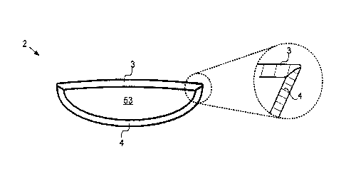
way described in Fig. 7a, and thus enclose an interior space 53 indicated in
Fig. 7b, in
which, for example, a circuit board (not shown in further detail) can be
incorporated as
an electronics assembly of the remote control 1.
When assembling the upper casing 3 and lower casing 4 in the joining direction
52, the
two casings 3, 4 are centred automatically at the mitred surfaces 36. This
ensures a
flush closure between the upper casing 3 and the lower casing 4, as shown in
Fig. 7b,
and thus the previously mentioned monolithic appearance of the plastic housing
2.
Fig. 8a and 8b correspondingly show an example of an interior view of the
produced
upper casings 3 and lower casings 4. The view in Fig. 8a and 8b thus
corresponds to
what is created by the half 40 on the locking side of the moulds.
The drawings clearly show the contact surfaces 55 where the ejector pins 27
touch to
correspondingly eject the upper casing 3 or lower casing 4 from the half 40 on
the locking
16
CA 03009260 2018-06-20
side. The ejector pins 27 and thus the contact surfaces 55 are formed to be
rectangular,
wherein the broadside of the rectangular shape extends in the circumferential
direction
around the upper casing 3 or the lower casing 4.
The ejector pins 27 and thus the contact surfaces 55 are arranged along an
edge 56
facing the interior space 53 of the upper casing 3 or lower casing 4. This is
to ensure
that the outer edges of the two casings 3, 4 close in a flush manner, and thus
the
monolithic appearance of the remote control is not disrupted.
The casings 3, 4 can be deepened at the contact surfaces 55 by means of the
ejector
pins 27.
Fig. 8a and 8b also correspondingly show pins 42' and sleeves 43' formed by
the pin-
moulding elements 42 and sleeve-moulding elements 43, not all of which are
marked with
their own reference signs for the sake of clarity. Fig. 8b also shows the
point 34', at which
the sprue 34 for the lower casing 4 ends. The corresponding point 34' on the
upper
casing is not shown in the perspective view in Fig. 8a.
17