Note : Les descriptions sont présentées dans la langue officielle dans laquelle elles ont été soumises.
=
LOW NO BURNER APPARATUS AND METHOD
FIELD OF THE INVENTION
[0001] The present invention relates to burner assemblies and to methods
and apparatuses for
reducing NOx emissions from burners of the type used in process heaters,
boilers, furnaces and other
fired heating systems.
BACKGROUND OF THE INVENTION
[0002] Many industrial applications require large scale generation of
heat from burners for
process heaters, boilers, furnaces, or other fired heating systems. If the
burner fuel is thoroughly
mixed with air and combustion occurs under ideal conditions, the resulting
combustion products are
primarily carbon dioxide and water vapor. However, when the fuel is burned
under less than ideal
conditions, e.g., at a high flame temperature, nitrogen present in the
combustion air reacts with
oxygen to produce nitrogen oxides (NOx). Other conditions being equal, NO
production increases
as the temperature of the combustion process increases. NOx emissions are
generally considered to
contribute to ozone depletion, acid rain, smog, and other environmental
problems.
[0003] For gaseous fuels with no fuel bound nitrogen, thermal NOx is the
primary mechanism of
NOx production. Thermal NO is produced when the flame reaches a high enough
temperature to
break the covalent N2 bond so that the resulting "free" nitrogen atoms then
bond with oxygen to form
NOx.
[0004] Typically, the temperature of combustion is not great enough to
break all of the N2
bonds. Rather, most of the nitrogen in the air stream passes through the
combustion process and
remains as diatomic nitrogen (N2) in the combustion products. However, some of
the N2 will
typically reach a high enough temperature in the high intensity regions of the
flame to break the N2
bond and form "free" nitrogen. Once the covalent nitrogen bond is broken, the
"free" nitrogen is
available to bond with other atoms. Fortunately, the free nitrogen will most
likely react with other
free nitrogen atoms to form N2. However, if another free nitrogen atom is not
available, the free
nitrogen will react with oxygen to form NOx.
[0005] As the temperature of the burner flame increases, the stability
of the N2 covalent bond
decreases, causing increasing production of free nitrogen and thus also
increasing the production of
thermal NOx emissions. Consequently, in an ongoing effort to
1
CA 3009668 2023-05-29
CA 03009668 2018-06-22
WO 2017/120114
PCT/US2016/069466
reduce NO emissions, various types of burner designs and theories have been
developed
with the objective of reducing the peak flame temperature.
[0006] The varied requirements of refining and petrochemical processes
necessitate
the use of numerous different types and configurations of burners. The
approaches used to
lower NO. emissions can differ from application to application. However,
thermal NO,
reduction is generally achieved by slowing the rate of combustion. Since the
combustion
process is a reaction between oxygen and the burner fuel, the objective of
delayed
combustion is typically to reduce the rate at which the fuel and oxygen mix
together and
burn. The faster the oxygen and the fuel mix together, the faster the rate of
combustion
and the higher the peak flame temperature.
[0007] Examples of different types of burner design approaches used for
reducing
NO emissions have included:
a. Staged air designs wherein the combustion air is typically separated into
two or more flows to create separate zones of lean and rich combustion.
b. Designs using Internal Flue Gas Recirculation (IFGR) wherein some of the
burner fuel passes through and mixes with the inert products of
combustion (flue gas) in the combustion system to form a diluted fuel
which burns at a lower peak flame temperature.
c. Staged fuel designs wherein the fuel is separated into two or more flows to
create separate zones of lean and rich combustion.
d. Designs using External Flue Gas Recirculation (EFGR) wherein inert
products of combustion are mixed with the combustion air to reduce the
oxygen concentration of the air stream supplied to the burner, which in
turn lowers the peak flame temperature.
e. Designs using "flameless" combustion wherein most or all of the burner
fuel passes through and mixes with inert products of combustion to form a
diluted fuel which burns at a lower peak flame temperature. The mixture of
fuel and inert products of combustion can be as high as 90% inert, thus
resulting in a "transparent" flame.
2
CA 03009668 2018-06-22
WO 2017/120114
PCT/US2016/069466
f. Designs using steam and/or inert injection into the burner fuel wherein the
steam or inert components mix with the fuel so that the resulting
composition will burn at a lower peak flame temperature.
g. Designs using steam and/or inert injection into the combustion air stream
wherein the steam and/or inert components mix with the combustion air so
that the resulting composition will burn at a lower peak flame temperature.
SUMMARY OF THE INVENTION
[0008]
The present invention provides a low NO burner apparatus and method which
achieve further reductions in NO emissions at lower cost, reduced complexity,
and
higher efficiency. The inventive burner and method provide both staged fuel
operation
and internal flue gas recirculation (1FGR) for lowering combustion
temperatures and
reducing NO emissions. In addition, the inventive burner and method allow the
entire
fuel stream to be conditioned with flue gas.
[0009]
In contrast to prior burners which require the use of a plurality of
individual
ejector tips, the inventive burner and method preferably employ a single
ejector ring with
tip, or an elongate bar-type fuel ejector, which increases the level of IFGR
provided by the
burner by (a) increasing the available ejection tip area of the burner, (b)
increasing the
number of ejection ports which can be used, (c) allowing the ejection ports
and the
resulting ejection streams to be positioned much closer together, and/or (d)
allowing the
use of a continuous or elongated ejection slot. The inventive burner and
method also
provide high levels of performance in regard to flame length, available
turndown ratio,
and stability.
100101
In one aspect, there is provided a burner apparatus preferably comprising: (a)
a
burner wall having a combustion zone projecting forwardly from or proximately
from a
forward end of the burner wall, wherein the burner wall surrounds a flow
passageway for
air or other oxygen-containing gas which extends longitudinally through the
burner wall
and the flow passageway has a longitudinally forward discharge opening at the
forward
end of said burner wall and (b) a fuel discharge ring which is positioned
outside of the
flow passageway and longitudinally rearward of the forward end of said burner
wall for
discharging a burner fuel, the fuel discharge ring substantially surrounding,
laterally, the
flow passageway. The fuel discharge ring preferably includes either (i) a
plurality of fuel
discharge openings which substantially surround the flow passageway and are
positioned
3
CA 03009668 2018-06-22
WO 2017/120114
PCT/US2016/069466
and oriented in a direct or angled forward direction to deliver the burner
fuel outside of
the burner wall to the combustion zone during operation or (ii) a single fuel
discharge slot
which substantially surrounds the flow passageway and is positioned and
oriented in a
direct or angled forward direction to deliver the burner fuel outside of the
burner wall to
the combustion zone during operation.
[0011] In another aspect, there is provided a burner apparatus
preferably comprising:
(a) a burner wall having a combustion zone projecting from or proximately from
a
forward end of the burner wall, wherein the burner wall surrounds a flow
passageway for
air or other oxygen-containing gas which extends longitudinally through the
burner wall,
the flow passageway has a longitudinally forward discharge opening at the
forward end of
the burner wall, and the flow passageway has at least one side at the forward
discharge
opening which is substantially flat and (b) an elongate fuel discharge conduit
which
extends laterally and is positioned outside of the one side of the flow
passageway and
longitudinally rearward of the forward end of the burner wall for discharging
a burner
fuel. The elongate fuel discharge conduit preferably includes either (i) a
plurality of fuel
discharge openings which extend along at least most of the elongate fuel
discharge
conduit and are positioned and oriented in a direct or angled forward
direction to deliver
the burner fuel outside of the burner wall to the combustion zone during
operation or (ii) a
single fuel discharge slot which extends along at least most of the elongate
fuel discharge
.. conduit and is positioned and oriented in a direct or angled forward
direction to deliver
the burner fuel outside of said burner wall to the combustion zone during
operation.
[0012] In another aspect, there is provided a method of operating a
burner which
preferably comprises the steps of: (a) delivering an oxygen-containing gas
through a flow
passageway surrounded by a burner wall, wherein the burner wall has a
longitudinal axis
which extends through the flow passageway, the flow passageway has a
longitudinally
forward discharge opening at a forward end of the burner wall, and the forward
end of the
burner wall has an outer lateral cross-sectional shape, and (b) discharging a
flow of burner
fuel forwardly from a fuel discharge ring such that the flow of burner fuel is
received in a
combustion zone which projects forwardly from or proximately from the forward
end of
the burner wall. The fuel discharge ring is positioned outside of the flow
passageway and
longitudinally rearward of the forward end of said burner wall. The flow of
burner fuel,
as it is discharged from the fuel discharge ring, has a lateral cross-
sectional shape which
4
CA 03009668 2018-06-22
WO 2017/120114
PCT/US2016/069466
substantially surrounds the flow passageway and corresponds to the outer
lateral cross-
sectional shape of the forward end of the burner wall.
[0013] Further aspects, features, and advantages of the present
invention will be
apparent to those of ordinary skill in the art upon examining the accompanying
drawings
and upon reading the following Detailed Description of the Preferred
Embodiments.
BRIEF DESCRIPTION OF THE DRAWINGS
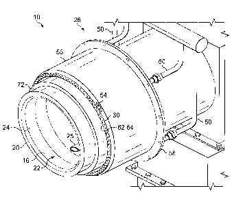
[0014] FIG. 1 is a perspective view of an embodiment 10 of the inventive
burner
apparatus.
[0015] FIG. 2 is an elevational side view of the inventive burner
apparatus 10.
[0016] FIG. 3 is a cutaway elevational side view of the inventive burner
apparatus 10.
[0017] FIG. 4 is an enlarged perspective view of a portion of the
inventive burner
apparatus 10.
[0018] FIG. 5 is a front view of an alternative embodiment 36 of a fuel
discharge ring
for use in the inventive burner apparatus 10.
[0019] FIG. 6 is an elevational side view of an alternative flat-flame
embodiment 100
of the inventive burner apparatus.
[0020] FIG. 7 is an elevational front view of the inventive burner
apparatus 100.
DETAILED DESCRIPTION OF THE PREFERRED EMBODIMENTS
[0021] An embodiment 10 of the inventive burner apparatus is illustrated
in FIGS. 1-
4. The inventive burner 10 preferably comprises: a housing 12 having an outlet
end 14; a
burner wall 16 which is positioned at the outlet end 14 of the housing 12 and
has a
longitudinal axis 18 which extends therethrough; an air flow passageway 22
which
extends through and is surrounded by the burner wall 16 and has a
longitudinally forward
discharge opening 24 at the forward end 20 of the burner wall 16; a fuel
discharge ring
assembly 26 for ejecting a gaseous or liquid burner fuel outside of the burner
wall 16
toward the forward discharge end 20 thereof; and at least one pilot burner
assembly 25
which extends through the discharge section 28 of the housing 12 and into the
air flow
passageway 22 of the burner wall 16.
[0022] The housing 12 has a windbox or other inlet 32 upstream of the
discharge
section 28 for receiving combustion air or other oxygen containing gas.
Combustion air
(or an alternative oxygen-containing gas) is received through the inlet 32 and
flows
through the housing 12 to the inlet end 35 of the burner wall 16. The air (or
other
5
CA 03009668 2018-06-22
WO 2017/120114
PCT/US2016/069466
oxygen-containing gas) then flows through the flow passageway 22 of the burner
wall 16
and exits the forward discharge opening 24 of the passageway 22. The quantity
of
combustion air entering housing 12 can be regulated using an inlet damper (not
shown) or
any other regulating device known in the art. Combustion air can be provided
to housing
12 by forced circulation, natural draft, a combination thereof, or in any
other manner
employed in the art.
[0023] The burner wall 16 is preferably constructed of a high
temperature refractory
burner tile material. However, it will be understood that the burner wall 16
could
alternatively be formed of or provided by the furnace floor, a metal band, a
refractory
band, or any other material or structure which is capable of (a) providing an
acceptable
combustion air flow orifice (i.e., passageway) into the fired heating system
and (b)
withstanding high temperature operating conditions.
[0024] The inventive burner 10 can be installed, for example, through a
floor or wall
38 of a boiler, fired heater, furnace or other fired heating system 40.
Consequently, the
forward (discharge) end 20 of burner wall 16 is in communication with the
interior 42 of
the fired heating system 40 in which combustion takes place. As a result of
the
combustion process, the interior 42 of the fired heating system 40 will
contain inert
combustion product gases (i.e., flue gas) 44. An insulating material 46 will
also typically
be secured to the interior surface of the floor or wall 38 outside of the
burner wall 16.
100251 The burner wall 16 and the air flow passageway 22 extending
therethrough
will preferably have round (circular) cross-sectional shapes. However, it will
be
understood that the cross-sectional shapes of the burner wall 16 and the air
flow
passageway 22 can alternatively be square, rectangular, oval, or generally any
other shape
desired.
[00261 The fuel discharge tip assembly 26 used in the inventive burner 10
preferably
comprises a fuel discharge ring 30 which is positioned rearwardly of the
forward
discharge end 20 of the burner wall 16 and outside of the air flow passageway
22.
Although a "ring" may typically be thought of as having a circular shape, the
"fuel
discharge ring" referred to herein and in the claims, unless otherwise
expressly specified
or limited, can be circular, square, rectangular, oval, or any other desired
shape.
[0027] In most cases, it will be preferred that the shape of the fuel
discharge tip 30
correspond to the lateral cross-sectional shape of the burner wall 16, or at
least the
6
CA 03009668 2018-06-22
WO 2017/120114
PCT/US2016/069466
forward end 20 thereof. In addition, the fuel discharge ring 30 will
preferably have an
inside diameter, or other inside dimensions in the case of a square,
rectangular, oval, or
other non-circular burner, which is/are greater than or equal to the outside
diameter or
other outer dimensions of the discharge end 20 of the burner wall 16.
[0028] The fuel discharge ring assembly 26 preferably also comprises: a
fuel supply
manifold 48; a fuel supply line (not shown) which supplies a gas or liquid
burner fuel to
the fuel manifold 48; and one or more (preferably a plurality of) fuel riser
lines 50 which
extend from the fuel supply manifold 48 to the fuel discharge ring 30.
[0029] When the inventive burner 10 is installed in the fired heating
system 40, the
fuel manifold 48 of the fuel discharge ring assembly 26 is preferably
positioned outside of
the floor or wall 38 of the fired heating system 40. The fuel riser lines 50
of the ring
assembly 26 can extend from the fuel supply manifold 48, which is positioned
outside of
the heating system 40, to the fuel discharge ring 30 in the interior 42 of the
heating system
40 either (a) through a radially extending refractory base which can be foimed
on and as
part of the burner wall 16, (b) through the layer of insulating material 46
which is secured
to the interior surface of the floor or wall 38 of the heating system 40
outside of the
burner wall 16, or (c) through a gap 52 between the base of the burner wall 16
and the
surrounding layer of insulating material 46.
[0030] Although a plurality of riser lines 50 are shown in FIGS. 1-4, it
will be
understood that a single riser line 50 can alternatively be used in the fuel
discharge ring
assembly 26. However, in order to provide a more equalized discharge of fuel
around the
entire circumference of the fuel discharge ring 30, the fuel discharge ring
assembly 26
will preferably comprise at least 2, more preferably comprise at least 3, and
most
preferably at least 4, riser line connections 54 which are evenly spaced
around the fuel
discharge ring 30.
[0031] Also, the fuel discharge ring assembly 26 will preferably further
comprise an
outer protection sleeve 56 which surrounds the riser lines 50. The outer
protection sleeve
56 preferably extends longitudinally from the furnace wall attachment flange
58 of the
burner 10 to, or proximately to, the fuel discharge ring 30.
[0032] The fuel discharge ring 30 preferably entirely surrounds or
substantially
surrounds (i.e., extends from at least 95% to 100% of the entire distance
around) the air
flow passageway 22 of the burner wall 16. The fuel discharge ring 30
preferably has
7
CA 03009668 2018-06-22
WO 2017/120114
PCT/US2016/069466
either one fuel discharge slot 60 (see alternative discharge ring 36 shown in
FIG. 5) or a
plurality of fuel discharge slots, ports or other openings 62 which is/are
formed through
the forward surface 64 of the fuel discharge ring 36 or 30 such that the slot
or the plurality
of other openings 60 or 62 substantially surround(s) or entirely surround(s)
the air flow
passageway 22. The plurality of fuel discharge openings 62, if used, will
preferably be a
plurality of round holes which are spaced from about 0.5 to about 200
diameters apart.
[0033] The size and orientation of the fuel discharge slot 60 or the
plurality of other
openings 62 and the fuel pressure supplied to the fuel discharge ring 30 or 36
are
preferably such that the gas or liquid burner fuel is discharged from the slot
60 or other
openings 62 in free jet flow outside of the burner wall in a direct or angled
forward
direction such that the ejected fuel flows along any desired straight or
curving forward
path to a combustion zone 66 which begins at or proximate to (i.e., within
from 0 to + 0.5
inches of) the forward end 20 of the burner wall 16. The fuel discharge slot
60 or
plurality of other openings 62 is/are preferably oriented such that the fuel
is ejected
toward the outer edge 68 of the forward end 20 of the burner wall 16.
[0034] As the fuel ejected from the fuel discharge ring 30 or 36 travels
toward the
combustion zone 66 through the flue gas 44 in the interior 44 of the fired
heating system
40, Internal Flue Gas Recirculation (IFGR) occurs wherein an amount of inert
flue gas
mixes with and conditions the ejected fuel. This conditioning of the fuel with
inert flue
gas slows the burning of the fuel in the combustion zone 66, thus reducing NOx
production by lowering the peak temperature of the burner flame. In addition,
IFGR
mixing is further enhanced significantly by the momentum of the combustion air
(or other
oxygen-containing gas) exiting the forward discharge opening 24 of the burner
wall 16
which pulls additional flue gas into the fuel and into the combustion zone 66.
[0035] To further promote the entrainment and mixing of the flue gas with
the fuel
ejected from the fuel discharge ring 30 or 36, the inventive burner 10
preferably includes
one or more exterior impact structures positioned at least partially in the
flow path of the
fuel ejected from the fuel discharge ring 30 or 36. Each impact structure can
generally be
any type of obstruction which will decrease the flow momentum and/or increase
the
turbulence of the fuel stream sufficiently to promote flue gas entrainment and
mixing
while allowing the resulting mixture to flow on to the combustion zone 66.
8
CA 03009668 2018-06-22
WO 2017/120114
PCT/US2016/069466
[0036] In this regard, the burner wall 16 employed in the inventive
burner 10 is
preferably formed to provide a tiered exterior shape wherein the outer
diameter of the
base 70 of the burner wall 16 is broader than the outer diameter of the
forward end 20
thereof and the exterior of the burner wall 16 includes one or a series of
surrounding,
spaced apart, impact ledges. By way of example, the outermost impact ledge of
the
burner wall 16 is defined by the outer edge 68 of the forward end 20 of the
burner wall 16.
At least one additional impact ledge 72 is then positioned around the exterior
of the
burner wall 16 between the fuel discharge ring 30 and the forward end 20 of
the burner
wall 16. The forward end 20 of the burner wall 16, which surrounds the forward
air
discharge opening 24, also forms a flame stabilization ledge for the
combustion zone 66
of the inventive burner 10.
[00371 IFGR and flame stability are additionally increased in the
inventive burner 10
by the formation of a plurality of ports, slots, or other openings 62, or of a
single slot 60,
in the fuel discharge ring 30 or 36, as discussed above, which substantially
surround(s) or
entirely surround(s) the air flow passageway 22. As also indicated above, when
a
plurality of discrete ports or slots 62 are used, the ports or slots 62 will
preferably be
spaced close together (i.e., preferably only from about 0.5 to about 200 port
diameters or
slot widths apart).
[0038] Consequently, as compared to the prior use of a plurality of
individual fuel
ejection tips, the inventive fuel discharge ring 30 or 36 significantly
increases the total
effective available tip area, thus allowing either (a) the use of a
significantly greater
number of ports 62 which are positioned closer together or (b) the use of a
single
surrounding fuel ejection slot 60 or a plurality of slots that are spaced only
a short
distance apart. These port or slot arrangements and reduced spacing provide an
even
greater degree of flue gas entrainment and flame stability.
[00391 To also enhance the equalization of air flow over the entire
cross-section of the
passageway 22 and/or change the shape of the flame if desired, a swirler 74 of
the type
commonly used in burners can optionally be positioned in the air flow
passageway 22.
[0040] In addition to providing reduced peak flame temperatures and
lower NO
.. levels using IFGR as discussed above, the inventive burner 10 also achieves
further flame
temperature and NO level reductions by providing staged fuel operation in the
combustion zone 66. By ejecting the fuel outside of the burner wall 16 into
the exterior
9
CA 03009668 2018-06-22
WO 2017/120114
PCT/US2016/069466
base portion 76 of the air flow discharged from the outer end 20 of the burner
wall 16, the
inventive burner 10 causes the combustion zone 66 to have (a) an outer
surrounding fuel
rich combustion region 78 and (b) an interior fuel lean combustion region 80.
[0041] In the outer fuel rich region 78 of the combustion zone 66,
combustion occurs
.. in an excess fuel to air ratio. In the inner lean combustion region 80, on
the other hand,
combustion occurs in an excess air to fuel ratio.
[0042] Also, it will be understood that further reduction in NO
emissions can be
achieved in the inventive burner and method by optionally including the
additional use of
(a) external flue gas recirculation, (b) steam and/or inert injection into the
combustion air
.. stream, (c) steam and/or inert injection into the combustion fuel stream,
(d) flameless
combustion, (e) one or more additional fuel ejection ring(s) or tips for
further staged fuel
operation, and/or (1) alternative port drillings to achieve staged combustion.
[0043] When operating the inventive burner 10 for combustion of a gas or
liquid
burner fuel in the fired heating system 40, air or other oxygen-containing gas
is delivered
through the flow passageway 22 surrounded by the burner wall 16. At the same
time, a
flow of the burner fuel is discharged forwardly, preferably in free jet form,
from the fuel
discharge ring 30 or 36 such that the flow of burner fuel is received in the
combustion
zone 66. Preferably, the free jet flow of burner fuel from the fuel discharge
ring 30 or 36
is ejected directly toward the outer edge 68 of the forward end 20 of the
burner wall 16.
[0044] As the flow of burner fuel is discharged from the fuel discharge
ring 30 or 36,
the flow preferably has a lateral cross-sectional shape which (a)
substantially surrounds
the flow passageway 22 and (b) corresponds to the outer lateral cross-
sectional shape of
the forward end 20 of the burner wall 16.
[0045] An alternative embodiment 100 of the inventive burner is
illustrated in FIGS.
.. 6 and 7. The structure and operation of the inventive burner 100 are
substantially the
same as the inventive burner 10 except that the inventive burner 100 is a flat
flame burner
wherein (a) the burner wall 116 and the air flow passageway 126 extending
therethrough
have a wide, flatter, rectangular shape, (b) the fuel discharge ring 30 of
burner 10 is
replaced with a T-bar ejector 130 having an elongate ejection tube or other
conduit 132
.. which extends laterally adjacent to and across the exterior of the flat
side 125 of the
burner wall 116, (c) the burner 100 preferably does not include a burner fuel
manifold,
CA 03009668 2018-06-22
WO 2017/120114
PCT/US2016/069466
and (d) the T-bar ejector preferably has only a single fuel riser 134 which
extends to the
middle of the lateral ejection conduit 132.
[0046] The T-bar ejector 130 preferably has either a single elongate
slot or a plurality
of ports, slots or other openings 135 which extend(s) along at least most of
the length of
the forward surface 136 of the lateral ejection conduit 132, preferably from
or proximately
from one end 138 to or proximately to the other end 140 of the lateral conduit
132.
Where a plurality of slot openings or circular port openings 135 are used, the
openings are
preferably only spaced from about 0.5 to 200 diameters or slot widths apart.
[0047] The single slot, or at least most, preferably all, of the
plurality of slots or other
openings, 135 provided in the lateral ejection conduit 132 is/are preferably
oriented to
eject the burner fuel toward the laterally extending outer edge 142 of the
forward end 144
of the burner wall 116 on the flat side 125 of the burner. At least one
additional impact
ledge 146 is preferably also provided or formed in the exterior of the burner
wall 116
between the forward outer edge 142 and the fuel ejection conduit 132.
* * * * *
[0048] Thus, the present invention is well adapted to carry out the
objectives and
attain the ends and advantages mentioned above as well as those inherent
therein. While
presently preferred embodiments and steps have been described for purposes of
this
disclosure, the invention is not limited in its application to the details of
the preferred
embodiments and steps. Numerous changes and modifications will be apparent to
those of
ordinary skill in the art. Such changes and modifications are encompassed
within this
invention as defined by the claims. In addition, unless expressly stated, the
phraseology
and terminology employed herein are for the purpose of description and not of
limitation.
11