Note : Les descriptions sont présentées dans la langue officielle dans laquelle elles ont été soumises.
CA 03009747 2018-06-26
WO 2017/115073
PCT/GB2016/054021
1
Thermally Broken Truss
The present invention relates to a thermally broken truss, and more
particularly but not
necessarily exclusively to a thermally broken truss for a cage of a thermally
broken structural
building panel. The invention also relates to the thermally broken structural
building panels
themselves, using such a thermally broken truss.
It is known to construct buildings, such as houses and commercial and
industrial buildings
and structures, using prefabricated building panels. Such panels are formed
off-site, ready for
use as and when required. Typically, the panels are used in the floors, in the
building walls, in
the foundations and in the roof A key reason why prefabricated building panels
are widely
used is that they help to reduce the time required on site for building
construction.
The known prefabricated panel is limited in terms of its insulation
properties.
At present, increasing the energy efficiency of buildings has become one of
the most
widespread goals in the construction industry. However, efforts to reduce
building energy use
are typically focused on the mechanical, electrical and glazing systems and
not the structural
system.
Typical methods of construction for buildings, such as residential houses and
commercial and
industrial buildings, using prefabricated building panels are either not
sufficiently energy
efficient or too costly for an average buyer once the cost of the necessary
components to
make them energy efficient is accounted for.
A thermal break or thermal barrier is an element of low thermal conductivity
placed in an
assembly to reduce or prevent the flow of energy between conductive materials.
Thermal
breaks made of polyamide or polyurethane are known to be in the order of a
thousand times
less conductive than aluminium and a hundred times less than steel. Providing
a thermal
break in a truss for a cage of a structural building panel will lead to
improved efficiency,
performance and costs savings.
It is an object of the present invention to provide a thermally broken truss
and/or a structural
building panel which reduces or substantially obviates the above mentioned
problems. In
brief, it is the object of the invention to provide a structural building
panel which meets the
CA 03009747 2018-06-26
WO 2017/115073 PCT/GB2016/054021
2
industry demands for improved heat insulation properties, and which also has a
low
manufacturing cost and a low weight.
According to a first aspect of the invention, there is provided a thermally
broken truss for a
cage of a structural building panel, comprising: first and second elongate
outer support
members; first and second elongate intermediate support members interposed
between the
first and second outer support members; at least one first connecting member
interconnecting
the first outer support member and the first intermediate support member; at
least one second
connecting member interconnecting the second outer support member and the
second
intermediate support member; and a thermally insulative fastener which fastens
the first and
second intermediate support members together in spaced apart relationship,
thereby providing
a thermal break between the first and second elongate outer support members.
The thermally broken truss is advantageous as providing a thermal break in a
truss for a cage
of a structural building panel will reduce or prevent the flow of unwanted
energy. If the
thermally broken truss is used in a structural building panel, a break in the
thermal path will
prevent or reduce heat energy from transferring between the interior and the
exterior of the
building. Whilst, thermal breaks are traditionally used in colder climates,
they are equally
important in warm environments to reduce heat transfer in air conditioned
buildings and can
lead to improved energy efficiency, performance and costs savings.
Preferably, the thermally insulative fastener may be a sheath in which the
first and second
intermediate support members are received.
Beneficially, this provides that both the first and second intermediate
support members are
housed in an insulative material, greatly reducing the flow of energy between
the first and
second intermediate barriers and providing a thermal barrier therebetween.
The thermally broken truss may further comprise at least one reinforcement
element which
buttresses the thermally insulative fastener and is held in a spaced
relationship from the first
and second intermediate support members by the thermally insulative fastener.
Preferably,
the reinforcement element may be a strap or a collar and may be composed of,
or include,
metal. Further, the reinforcement element may encircle at least part of the
first and second
intermediate support members.
Advantageously, this reinforcement element may provide support to the
thermally broken
CA 03009747 2018-06-26
WO 2017/115073 PCT/GB2016/054021
3
truss and protect the integrity of the thermally insulative fastener, and may
help prevent
tensile stress from disrupting the structure of the thermally broken truss.
Most preferably, the reinforcement element may be spaced apart from the first
and second
connecting members. This is beneficial, in reducing energy flow from the first
and second
.. intermediate members to the first and second outer support members via the
first and second
connecting members.
In one embodiment, the thermally insulative fastener may be provided in a gap
between the
first and second intermediate support members. In addition, the thermally
insulative fastener
may be composed of or include polystyrene, polyurethane foam, or polyamide.
Further the
.. thermally insulative fastener may be composed of or include adhesive.
Advantageously, these
materials are far less conductive than metal and, as above, provide a thermal
break between
the first and second intermediate support members, thereby preventing or
reducing the flow
of thermal energy from the first intermediate support member to the second
intermediate
support member, or vice versa.
The thermally insulative fastener may be connected to at least one of the
first or second
intermediate support members using a connective means. Preferably, the
connective means
may include adhesive.
Optionally, the first outer support member and first intermediate support
members may be in
coplanar or substantially coplanar alignment. Further, the first outer support
member and first
intermediate support member may be disposed on opposing sides of the first
connecting
member. Preferably, the first connecting member interconnects the first outer
support
member and first intermediate support member. Additionally, the first
connecting member
may zig zag along the longitudinal axis of the thermally broken truss.
Ideally, the first
connecting member may be unitarily formed and/or continuous.
Optionally, the second outer support member and second intermediate support
member may
be in coplanar or substantially coplanar alignment. Further, the second outer
support member
and second intermediate support member may be disposed on opposing sides of
the second
connecting member. Preferably, the second connecting member interconnects the
second
outer support member and second intermediate support member. Additionally, the
second
connecting member may zig zag along the longitudinal axis of the thermally
broken truss.
Ideally, the second connecting member may be unitarily formed and/or
continuous.
CA 03009747 2018-06-26
WO 2017/115073 PCT/GB2016/054021
4
Advantageously, the first and second connecting members act as a brace between
the first
intermediate support member and the first outer support member and, the second
intermediate
support member and the second outer support member, respectively, and maintain
these at a
fixed distance apart. Beneficially, the first and second connecting members
reduce the risk of
the first and second intermediate support members and the first and second
outer support
members bending or deforming under an applied load. Additionally, when a truss
is cut to
size, there is a tendency for struts of a non-continuous connecting member to
spring out of
position as they are under a certain amount of internal tension during
cutting. This risk is
minimised by having a unitarily formed and/or continuous connecting member.
Preferably, the first connecting member may form a plurality of triangles with
the first outer
support member and first intermediate support member. In addition, the second
connecting
member may form a plurality of triangles with the second outer support member
and second
intermediate support member. Optionally, the plurality of triangles may be
equilateral or
isosceles triangles.
Preferably, the first connecting member may be welded to the first outer
support member and
first intermediate support member. In addition, the second connecting member
may be
welded to the second outer support member and second intermediate support
member.
Optionally, a lateral cross-section of any or more of the first and second
outer support
members or first and second intermediate support members may be circular, or
substantially
circular. Further, the diameter of any two or more of the first and second
outer support
members or first and second intermediate support members may be different.
Alternatively,
the diameter of any two or more of the first and second outer support members
or first and
second intermediate support members may be the same. In one embodiment, any or
more of
the first and second outer support members or first and second intermediate
support members
may be substantially flat elongate plates.
Advantageously, this means that a variety of different first and second
intermediate support
members or first and second outer support members may be used, depending on
the user
requirements of a particular thermally broken truss. If any of the first and
second outer
support members or first and second intermediate support members are
substantially flat
elongate plates, these may overlap and provide a large surface area for any
thermally
insulative fastener to be adhered to.
CA 03009747 2018-06-26
WO 2017/115073 PCT/GB2016/054021
Preferably, the first and second outer support members and the first and
second intermediate
support members may be in coplanar alignment. Alternatively, the first outer
support member
and the first intermediate support member may be offset from the second outer
support
member and the second intermediate support member.
5 Preferably, the first and second outer support members may further be
sheathed in an
insulative material of substantially the same form as the thermally insulative
fastener.
This is helpful in adding another layer of thermal insulation, further
reducing or preventing
thermal energy transfer from the first and second outer support members to the
first and
second connecting members and across the thermally broken truss.
According to a second aspect of the present invention, there is provided a
thermally broken
structural building panel comprising: at least one insulation member; at least
two thermally
broken trusses in accordance with the first aspect of the invention; and at
least one strapping
member, wherein the thermally broken trusses are arranged in substantially
parallel planes
and the insulation member is disposed intermediate the thermally broken
trusses, the
strapping member interconnecting the at least two thermally broken trusses and
extending
substantially perpendicularly to the at least two thermally broken trusses for
retaining the
insulation member therebetween.
This construction is beneficial due to the presence of the earlier described
thermally broken
trusses as part of the structural building panel.
The insulation member improves the thermal insulation properties of the
structural building
panel, thereby contributing to a strong, lightweight and insulated
prefabricated panel.
Preferably, a plurality of insulation members, thermally broken trusses and
strapping
members are provided. More preferably, at least two of the said insulation
members are
joined together using joining means. Furthermore, the insulation member may be
composed
of or include polystyrene, polyurethane, or polyamide. Beneficially, these
materials provide
good thermal insulation.
This thermally broken structural building panel is beneficial not only for the
environment, but
also for the building owner / occupier, whose heating bills will be
correspondingly lower in
the long term. Notably, a thermally broken structural building panel
incorporating the
CA 03009747 2018-06-26
WO 2017/115073 PCT/GB2016/054021
6
thermally broken truss, improves the standard insulation rate of a building.
According to a third aspect of the present invention, there is provided a
thermally broken
truss for a cage of a structural building panel, comprising: at least two
modular units, each
modular unit including, elongate first and second support members defining
longitudinal edge
portions of the modular unit, the first and second support members being
adjacent to and in
spaced parallel or substantially parallel relationship with one another; and
at least one
connecting member which extends between the longitudinal edge portions and
which
interconnects the first and second members, each modular unit being coplanar
or substantially
coplanar and arranged in a spaced parallel or substantially parallel
relationship with one
another, the spaced relationship between the modular units defining a gap; a
thermally
insulative fastener disposed in the gap intermediate a pair of parallel
modular units
interconnecting the at least two modular units; and a reinforcement element
reinforcing the
interconnection between the or each pair of parallel modular units and the
thermally
insulative fastener interconnecting the at least two modular units, whereby
the gap and the
thermally insulative fastener together substantially provide a thermal break
between coplanar
modular units.
The invention will now be more particularly described, by way of example only,
with
reference to the accompanying drawings, in which:
Figure 1 shows a perspective view from above of a thermally broken truss, in
accordance
with the invention.
Figure 2 shows a cross sectional view of the thermally broken truss taken
along line A-A in
Figure 1.
Figure 3 shows a plan view from above of the thermally broken truss shown in
Figure 1.
Figure 4 shows a perspective view from above of a plurality of the thermally
broken trusses,
shown in Figure 1.
Figure 5 shows a perspective view of a thermally broken structural building
panel in
accordance with the second aspect of the invention, which incorporates the
thermally broken
truss of Figure 1.
Figure 6 shows perspective view from the side of a thermally broken structural
building panel
CA 03009747 2018-06-26
WO 2017/115073 PCT/GB2016/054021
7
in accordance with the second aspect of the invention, which incorporates the
thermally
broken truss of Figure 1.
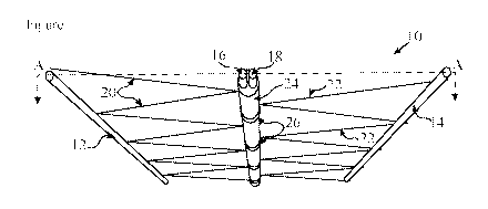
Referring to the drawings, a thermally broken truss for a cage of a structural
building panel is
indicated generally at 10. The thermally broken truss comprises first and
second longitudinal
outer support members 12, 14; first and second elongate intermediate support
members 16,
18 interposed between the first and second outer support members 12, 14; at
least one first
connecting member 20 interconnecting the first outer support member 12 and the
first
intermediate support member 16; at least one second connecting member 22
interconnecting
the second outer support member 14 and the second intermediate support member
18; and a
.. thermally insulative fastener 24 which fastens the first and second
intermediate support
members 16, 18 together in spaced apart relationship, thereby providing a
thermal break
between the first and second outer support members 12, 14.
The first and second outer support members 12, 14 and first and second
intermediate support
members 16, 18 are preferably rigid or substantially rigid struts of wire or
cord, and may be
or include metal, for example, steel. Typically, the first and second outer
support members
12, 14 and first and second intermediate support members 16, 18 are made from
a drawing
process. It is envisaged that suitable alternative materials and manufacturing
processes may
be used, if available. The first and second outer support members 12, 14 and
first and second
intermediate support members 16, 18 are the main load bearing structural
elements of the
thermally broken truss 10 through which most of any applied load is
transmitted. The length
of the first and second outer support members 12, 14 and first and second
intermediate
support members 16, 18 may be in a range of 100 to 6000 mm.
The first and second outer support members 12, 14 and first and second
intermediate support
members 16, 18 may have a circular lateral cross section. In such an
arrangement, the
diameter of any two or more of the first and second outer support members 12,
14 or first and
second intermediate support members 16, 18 may be the same or different.
Preferably the
diameter of the first and/or second outer support members 12, 14 and the first
and/or second
intermediate support members 16, 18 is in a range of 1 to 6 mm. More
preferably, the
diameter of the first and/or second outer support members 12, 14 and the first
and/or second
intermediate support members 16, 18 is in a range of 2 to 8mm. Although
preferably circular,
the lateral cross-section may be non-circular, such as polygonal, for example,
square or
rectangular.
CA 03009747 2018-06-26
WO 2017/115073 PCT/GB2016/054021
8
Alternatively, any or more of the first and second outer support members 12,
14, and first and
second intermediate support members 16, 18 may be substantially flat elongate
plates with a
rectangular lateral cross section. Preferably, the rectangular lateral cross
section of the first
and/or second outer support members 12, 14 and the first and/or second
intermediate support
members 16, 18 is in a range of 30 to 70 mm by 260 to 340 mm. More preferably
the
rectangular lateral cross section of the first and/or second outer support
members 12, 14 and
the first and/or second intermediate support members 16, 18 is 50 mm by 300
mm.
The first and second intermediate support members 16, 18 are positioned spaced
apart from
each other. Preferably, a gap between the first and second intermediate
support members 16,
18, defined by the spaced apart relationship, is in the range of 60 to 100 mm,
and more
preferably, is approximately 60 mm.
A thermally insulative fastener 24 maintains the gap between the first and
second
intermediate support members 16, 18 relative to one another. In this
embodiment, the
thermally insulative fastener 24 is preferably a sheath in which the first and
second support
members are held. The thermally insulative fastener 24 advantageously encloses
both the first
and second intermediate support members and may have a substantially circular
lateral cross
section. Preferably, the thermally insulative fastener covers the length of
the first and second
intermediate support members 16, 18. Consequently, there is provided a thermal
break
between the first and second intermediate support members 16, 18, and thermal
energy flow
from the first intermediate support member 16 to the second intermediate
support member 18,
or vice versa, is greatly reduced.
Although the thermally insulative fastener 24 is continuous, it may be
discontinuous forming
a plurality of thermally insulative fasteners disposed between the first and
second
intermediate support members 16, 18. It should be noted that air is known to
be a reasonable
thermal insulator and so, provided the thermally insulative fastener(s) act to
maintain the
spaced relationship between the first and second intermediate support members
16, 18, the
thermally insulative fastener(s) need not extend the full length of the first
and second
intermediate support members 16, 18. It will also be appreciated that other
configurations of a
thermally insulative fastener may be utilised instead. The thermally
insulative fastener may
instead be provided solely in the gap between the first and second
intermediate support
members 16, 18 and may be adhered to at least one of the first and second
intermediate
support members 16, 18 using joining means. The joining means may be or
include adhesive.
CA 03009747 2018-06-26
WO 2017/115073 PCT/GB2016/054021
9
Typically, the thermally insulative fastener 24 is or includes polystyrene and
preferably
expanded polystyrene. Polyurethane may be used instead, or indeed any fastener
providing
some thermal break between the first and second intermediate support members,
such a
polyamide. Further, the thermally insulative fastener, may be composed of or
include
adhesive. Advantageously, thermal breaks made of polyamide or polyurethane can
be more
than a thousand times less conductive than aluminium and a hundred times less
than steel.
At least one reinforcement element 26 assists in maintaining the integrity of
the thermally
insulative fastener, together with the first and second intermediate support
members 16, 18.
In the drawings, a plurality of reinforcement elements 26 are provided which
extend across
the first and second intermediate support members 16, 18 and are held in a
spaced
relationship from the first and second intermediate support members 16, 18 by
the thermally
insulative fastener 24.
The or each reinforcement element 26 extends across and is connected to the
thermally
insulative fastener 24. Preferably, the or each reinforcement element 26 may
take the form of
a strap or collar and encircle the thermally insulative fastener 24; and
consequently, also
encircle the first and second intermediate support members 16, 18.
Advantageously, to aid the reinforcement mechanism of the reinforcement
element 26, the or
each reinforcement element 26 may be or may include metal. Consequently, in
order to
maintain the thermal efficiency of the thermally broken truss 10, the or each
reinforcement
element 26 is spaced apart from the first and second intermediate connecting
members 16, 18.
The first outer support member 12 and first intermediate support member 16 are
in coplanar
or substantially coplanar alignment. The distance between the first outer
support member 12
and first intermediate support member 16 is preferably in a range of 30 mm to
90 mm. More
preferably, the distance is in a range of 40 mm to 80 mm. The second outer
support member
14 and second intermediate support member 18 are in coplanar or substantially
coplanar
alignment. The distance between the second outer support member 14 and second
intermediate support member 18 is preferably in a range of 30 mm to 90 mm.
More
preferably, the distance is in a range of 40 mm to 80 mm.
The first connecting member 20 interconnects the first outer support member 12
and first
intermediate support member 16. Preferably, the first connecting member 20 is
a preferably
rigid and continuous wire or cord-like strut similar to the first and second
outer support
CA 03009747 2018-06-26
WO 2017/115073
PCT/GB2016/054021
members 12, 14 and/or the first and second intermediate support members 16, 18
and may be
or include metal. The first connecting member 20 may have a circular or non-
circular lateral
cross-section. Preferably, the diameter of the first connecting member 20 is
in a range of 1
mm to 8 mm. The cross sectional area of the first connecting member 20 may be
the same of
5 different to that of the first and second outer support members 12, 14
and/or the first and
second intermediate support members 16, 18.
Beneficially, the first connecting member 20 braces the first outer support
member 12 and
first intermediate support member 16 at a fixed distance apart.
Advantageously, this reduces
the risk of the first outer support member 12 and first intermediate support
member 16
10 bending or deforming under an applied load.
Instead of being continuous, the first connecting member 20 may be
discontinuous and
alternatively, may comprise a plurality of discrete struts. Such struts made
be made from
length lengths of rigid wire or cord, typically 30 to 120mm long. When a
thermally broken
truss 10 is cut to size, there is a tendency for the struts of a non-
continuous connecting
member to spring out of position since they are under a certain amount of
internal tension
during cutting. However, the risk is minimised by using a unitarily formed
and/or continuous
connecting member.
The first connecting member 20 preferably zig zags along the longitudinal
extent of the first
outer support member 12 and first intermediate support member 16. The first
connecting
member 20 may form a series of triangles 28 with the first outer support
member 12 and first
intermediate support member 16. Preferably, the triangles 28 are equilateral
triangles, but
they may be isosceles or right-angled triangles instead.
Alternatively, if the first connecting member 20 is a non-connecting member as
described
above, the individual struts may each pass diagonally from first outer support
member 12 to
the first intermediate support member 16, or vice versa.
The first connecting member 20 is connected to the first outer support member
12 and first
intermediate support member 16 at or adjacent to each bend or apex 30 of a
plurality of nodes
32. Advantageously, the nodes 32 help to rigidify the thermally broken truss
10 and protect
the integrity of the thermally broken truss 10 from deformation under a non-
uniform load.
Each node 32 is preferably achieved through a spot weld. However, alternative
types of
fixing means may be used provided that a permanent connection is made.
CA 03009747 2018-06-26
WO 2017/115073
PCT/GB2016/054021
11
In compression, deformation of the first connecting member 20 is most likely
to occur at or in
close proximity to each bend or apex 30 of each zig zag. By placing the nodes
32 at or very
proximate each bend or apex 30, the thermally broken truss's resistance to
buckling is
increased. Such positioning of the nodes 32 significantly increases the load
bearing capability
of the thermally broken truss 10.
By having discreet nodes 32, the rigidity of the thermally broken truss 10 is
improved,
thereby making the thermally broken truss 10 more resistant to deformation
especially under
non-uniform loads, for example, during high winds or earthquakes.
Optionally, there may be a further first connecting member disposed between
the first outer
support member 12 and first intermediate support member 16. The further first
connecting
member is substantially the same as the first connecting member 20, and
therefore further
detailed description is omitted. Similarly to the first connecting member 20,
the further first
connecting member may be connected to the first outer support member 12 and
first
intermediate support member 16, at an additional plurality of nodes. The
additional nodes
may be similar to the nodes previously described, but spaced from the first
said nodes 32. The
benefit of a further first connecting member is that its presences increases
the nodal
connections and therefore further improves the rigidity of the thermally
broken truss 10.
Similarly to the first connecting member 20, the further first connecting
member may be a
non-continuous connecting member. In such an arrangement, the struts may
preferably
extend between the first outer support member 12 and first intermediate
support member 16
in an opposite direction to that of the first connecting member 20, with the
combination of
first connecting member 20 and further first connecting members forming a
lattice
arrangement.
The second connecting member 22 interconnects the second outer support member
14 and
second intermediate support member 18.The second connecting member 22 is
substantially
the same as the first connecting member 20, and therefore further detailed
description is
omitted.
The first and second outer support members 12, 14 and the first and second
intermediate
support members 16, 18 are preferably arranged in coplanar, or substantially
coplanar,
alignment, as best illustrated in Figure 3, with the first and second
connecting members 20,
22 offset from one another.
CA 03009747 2018-06-26
WO 2017/115073
PCT/GB2016/054021
12
It will be appreciated that, while a specific configuration of the first and
second outer support
members 12, 14 and the first and second intermediate support members 16, 18
and the first
and second connecting members 20, 22 is shown and described herein, this is
not limited to
any particular design, configuration or embodiment. For example, the first
outer support
member 12 and the first intermediate support member 16 may be offset from the
second outer
support member 14 and the second intermediate support member 18, with the
first and second
connecting members 20, 22 in coplanar alignment.
At least one bracing element 34 may be used to help brace the first and second
outer support
members 12, 14 of the thermally broken truss 10 and maintain them at a fixed
distance apart.
In this embodiment, the bracing element 34 is provided as a horizontal or
substantially
horizontal tie, which extends across and interconnects first and second outer
support
members 12, 14 and first and second intermediate support members 16, 18. Each
bracing
element 34 extends across and is connected to the thermally broken truss at at
least the first
and second outer support members 12, 14. However, each bracing element 34 may
be
connected to each of the first and/or second outer support members 12, 14
and/or each of the
first and/or second intermediate members 16, 18. Connection is preferably
achieved by
welding.
Preferably, each bracing element 34 may be housed in a further insulative
material 36 of the
or substantially the same form as the thermally insulative fastener 24.
Beneficially, this
prevents thermal energy transfer in a vertical direction.
Further, each of the first and/or second outer support members 12, 14 may be
sheathed in an
insulative material 38 of the or substantially the same form as the thermally
insulative
fastener 24.
In Figures 5 and 6, a thermally broken structural building panel is indicated
generally at 40.
The structural building panel comprises a plurality of insulation members 42
and plurality of
the thermally broken trusses 10. Features in common with the first aspect of
the invention are
denoted by the same reference numerals, for example component parts of the
thermally
broken truss 10 are indicated.
In this embodiment, each thermally broken truss 10 has first and second outer
support
members 12, 14, first and second intermediate support members 16, 18, first
and second
connecting members 20, 22, a thermally insulative fastener 24, a plurality of
reinforcement
CA 03009747 2018-06-26
WO 2017/115073
PCT/GB2016/054021
13
elements 26, and a bracing element 34. Preferably, each of the bracing element
34 and first
and second outer support members 12, 14 and are sheathed in insulative
material 36, 38 of the
or substantially the same form as the thermally insulative fastener 24.
One insulation member 42 is disposed between each pair of thermally broken
trusses 10.
Preferably, the material of the insulation member 42 provides good thermal
insulation. The
insulation member 42 may be or may include a low density material, for example
polystyrene, or more preferably expanded polystyrene. Polyurethane foam may be
used
instead. Polyurethane foam is a better insulator than polystyrene but it is
less environmentally
friendly than polystyrene.
Optionally, the insulation member 42 takes the form of a rectangular block.
Exemplary
dimensions of the insulation member 42 are: 2400 mm (length) x 40 mm (width) x
50 mm
(depth). Selection of the depth is important to the extent that it permits the
insulation member
42 to be fitted between adjacent thermally broken trusses 10, i.e. the depth
of the insulation
member 42 must be the same or less than the spacing between adjacent thermally
broken
trusses 10.
In Figures 4 to 6, each thermally broken truss 10 is arranged adjacent to
another thermally
broken truss 10 in parallel or substantially parallel spaced apart planes. A
plurality of
vertically spaced elongate retaining or strapping members 44 extend
perpendicularly to the
thermally broken trusses 10 to interconnect the thermally broken trusses 10
typically via the
first and second outer support members 12, 14. The plurality of thermally
broken trusses 10
and plurality of strapping members 44 together form a wire framework or cage
in which the
plurality of insulation members 42 are housed. The strapping members 44 help
to keep the
insulation members 42 in position between adjacent thermally broken trusses
10.
It is advantageous if there is a clearance between the insulation members 42
and the cage
once assembled together, as described in more detail below.
The strapping members 44 also maintain the thermally broken trusses 10 at a
fixed or
substantially fixed distance apart. A typical spacing between adjacent
thermally broken
trusses 10 is in a range of 40 mm to 60 mm, and more preferably the spacing is
approximately 50 mm. The strapping members 44 are positioned at regular
intervals along the
longitudinal extent of the thermally broken truss 10, typically every 50 mm.
CA 03009747 2018-06-26
WO 2017/115073
PCT/GB2016/054021
14
Each strapping member 44 is a preferably rigid wire or cord-like strut, and
may be or include
metal. Each strapping member 44 may have a circular or non-circular lateral
cross-section.
The diameter of each strapping member 44 may be in a range of 1 mm to 6mm.
However, the
strapping members 44 may be planar and provided as, for example, a continuous
sheet or
alternatively a mesh, which extends along or around at least a portion of the
thermally broken
structural building panel 40.
The strapping members 44 are preferably mounted to the thermally broken
trusses at a
plurality of positions using fixing means 46. Each strapping member 44 may be
connected to
every other thermally broken truss 10. However, alternative interval spacing
may be
considered, for example, a connection between each strapping member 44 and
every
thermally broken truss 10, or, a connection between each strapping member 44
and every
third thermally broken truss 10. Preferably, the fixing means 46 is a spot
weld. Alternatively,
the fixing means 46 may include a loop provided on one or more of the first
and/or second
outer support members 12, 14, through which the strapping member 44 passes,
thereby
securing the strapping member 44 to the thermally broken truss 10.
To form the thermally broken structural building panel 40, the thermally
broken trusses 10
and insulation members 42 are assembled together in an alternating sequence.
If desired, the
insulation members 42 are connected together during assembly using joining
means. Such
joining means may be or include an adhesive. The strapping members 44 are then
connected
to the thermally broken trusses 10.
With the thermally broken structural building panel 40 on site, a concrete
and/or plaster
render 48 is applied to opposing faces of the thermally broken structural
building panel 40.
Advantageously, the render 48 may add additional strength to the wire cage, if
so required.
The render 48 bonds to the first and second outer support members 12, 14, and
to the
strapping members 44. As it is intended that there is a clearance between at
least an
outwardly facing portion of the insulation member 42 and the wire cage,
beneficially, the
render 48 is able to enter the confines of the cage and bond to and around the
first and second
outer support members 12, 14 and the strapping members 44 from within the cage
as well as
outside of the cage. The bonding helps to improve the overall load bearing
capacity of the
thermally broken structural building panel 40, as the surface area available
for bonding is
increased.
CA 03009747 2018-06-26
WO 2017/115073
PCT/GB2016/054021
The render 48 typically comprises a weatherproofing mix of Portland cement,
aggregates and
sand. Alternatives, such as gypsum plaster, are commonly used for rendering
internal
surfaces. The layer of cement or plaster 48 encases the mesh cage on both
sides of the core
producing a strong and rigid structure when dry. If desired, various
waterproofing, anti-
5 fungal and fibre reinforcing agents may be applied to the rendering
mixture or the dried
surface. Internal and external surfaces are defined in this context as such
relative to the
constructed building.