Note : Les descriptions sont présentées dans la langue officielle dans laquelle elles ont été soumises.
CA 09010017 2018-06-27
WO 2017/120116 PCT/US2016/069489
=
ANAMORPHIC PHOTOGRAPHY FOR DIGITAL IMAGERS
CROSS-REFERENCE TO RELATED APPLICATIONS
100011 This application claims priority to, and the benefit of, Provisional
Application No.
62/275,733, filed January 6, 2016 and U.S. Non-Provisional Patent Application
Serial No.
15/394,401, filed on December 29, 2016,
BACKGROUND
100021 Anamorphic camera systems have been utilized to capture a widescreen
aspect ratio
on film that has a smaller aspect ratio, such as standard 35 mm film. For
example, in the
standard Panavision anamorphic system, a widescreen image having an aspect
ratio of 2.4:1
is compressed in a horizontal dimension by a factor of 2, to be captured on 35
mm film at an
aspect ratio of 1.2:1. The horizontal compression allows a higher resolution
image to be
stored on 35 mm film than would otherwise be allowed if a 2.4:1 aspect ratio
were stored on
35 mm film. Anamorphic lens elements are used to compress the original image
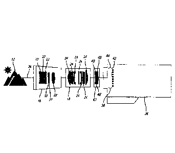
to be stored
on film, and are then used to expand the image again for projection in a
cinema or the like.
100031 With the expanded use of digital camera systems, further developments
to
anamorphic systems are required to address the needs of such digital camera
systems. In
addition, modifications to the anamorphic compression ratio are needed to
address the aspect
ratios utilized by digital imaging sensors.
SUMMARY
10004) The systems, apparatuses, and methods disclosed herein are intended to
provide for
improved anamorphic systems for use with digital camera systems. In addition,
modifications to the anamorphic compression ratio disclosed herein address the
aspect ratios
provided by digital imaging sensors.
[0005] In one embodiment, the application discloses a digital camera
comprising a digital
image sensor and a lens group positioned along an optical axis. The lens group
includes at
least one anamorphic lens element configured to compress an image in a
horizontal or
1
Date Recue/Date Received 2023-05-23
CA 09010017 2018-06-27
WO 2017/120116
PCT/US2016/069489
vertical dimension; at least one powered lens element positioned between the
at least one
anamorphic lens element and the digital image sensor; and at least one
corrective lens
element positioned between the at least one powered lens element and the
digital image
sensor, and configured to reduce a blurring of the image in the horizontal or
vertical
dimension on the digital image sensor or decomposition the image in the
horizontal or
vertical dimension to substantially equalize the image quality in the
horizontal and vertical
dimension.
[0006] In one embodiment, the application discloses a digital camera system
comprising a
digital image sensor including an optical low pass filter. The system includes
at least one
anamorphic lens element configured to compress an image in a horizontal or
vertical
dimension. The system includes at least one corrective lens element configured
to be
positioned along an optical axis between the at least one anamorphic lens
element and the
optical low pass filter, and configured to reduce a blurring of the image in
the horizontal or
vertical dimension on the digital image sensor caused by the optical low-pass
filter.
[0007] In one embodiment, the application discloses a digital camera system
comprising at
least one anamorphic lens element configured to compress an image in a
horizontal or
vertical dimension by a squeeze ratio of approximately 1.29. The system
includes a digital
image sensor configured to receive the image compressed by the at least one
anamorphic lens
element.
BRIEF DESCRIPTION OF THE DRAWINGS
100081 Features and advantages of the systems, apparatuses, and methods as
disclosed
herein will become appreciated as the same become better understood with
reference to the
specification, claims, and appended drawings wherein:
[0009] FIG, 1 illustrates a schematic view of a camera capturing an image of
an object on
film.
[0010] FIG. 2 illustrates a diagram of blurring using a spherical lens
element.
[0011] FIG. 3 illustrates a diagram of blurring using an anamorphic lens
element
[0012] FIG, 4 illustrates a diagram of a representation of a modulation
transfer function
(MTF).
2
Date Recue/Date Received 2023-05-23
CA 09010017 2018-06-27
WO 2017/120116
PCT/US2016/069489
(00131 FIG. 5 illustrates a schematic view of a camera capturing an image of
an object on
film, according to an embodiment of the present disclosure.
100141 FIG. 6 illustrates a schematic view of at least one corrective lens
element, according
to embodiments of the present disclosure.
.. 10015] FIG. 7 illustrates a diagram of optics of a digital camera,
according to an
embodiment of the present disclosure.
10016] FIG. 8 illustrates a diagram of use of a 1.29 squeeze ratio, according
to an
embodiment of the present disclosure.
DETAILED DESCRIPTION
[0017] FIG. 1 illustrates a schematic view of a camera 10 utilizing an
anamorphic process
to capture an image of an object 12 on film 14. Anamorphic processes have been
used in
film applications, namely in motion picture and television filming, to provide
a widescreen
image capture, yet also enhance the use of the imaging area of a film, An
anamorphic
process includes compressing the image in a horizontal dimension, or a
vertical dimension, to
reduce the aspect ratio of the image as it is stored on film. During the
projection of the
imaged film at a later time, a reverse process is used to expand the image in
the horizontal or
vertical dimension, to reproduce the original uncompressed image.
10018) An anamorphic process has been used to capture images on 65 millimeter
(mm) film
in a system referred to as Ultra Panavision. The Ultra Panavision system
includes a camera
10 having an anamorphic lens group 16, a powered lens group 18, and 65 mm film
14 for
storing the images. The anamorphic lens group 16 includes a plurality of
anamorphic lens
elements 22. The anamorphic lens elements 22 are configured to compress the
image in a
dimension, which may be a horizontal or vertical dimension, by a squeeze ratio
of between
1.19 to 1.30, which may include a ratio of 1.25, or 1.255. The squeeze ratio
is the ratio of the
uncompressed image aspect ratio to the compressed image aspect ratio. The
anamorphic lens
element 22 may comprise a weak negative afocal system. The anamorphic lens
elements 22
may comprise cylindrical lens elements, and/or prism lens elements to produce
the
compression in the horizontal or vertical dimension. The anamorphic lens
elements 22 may
include an astigmatizer, which may be similar to the variable astigmatizer
disclosed in
Wallin, Anamorphosing System, U.S. Patent No. 2,890,622, issued June 16, 1959,
3
Date Recue/Date Received 2023-05-23
CA 09010017 2018-06-27
WO 2017/120116
PCT/US2016/069489
The variable astigmatizer may utilize
weak counter-rotating cylinders (e.g., one positive and one negative, or both
positive, or both
negative) that balance out the axial focus position of the powered and non-
powered axes
when effectuating focus.
[0019] The powered lens group 18 may include spherical lens elements 24 that
converge
and/or diverge the afocal image produced by the anamorphic lens group 16. The
powered
lens group 18 may be utilized to effectuate focus of the image. The powered
lens group 18
may operate in a similar manner and include similar elements as the focusing
lens disclosed
in Wallin, U.S. Patent No. 2,890,622. The powered lens group 18 may be
positioned along
an optical axis 26 between the anamorphic lens group 16 and the film 14.
[0020] The 65 mm film 14 includes an imaging area having a width in a
horizontal or
vertical dimension of approximately 48.62 mm, and a height in a respective
corresponding
vertical or horizontal dimension of approximately 22.10 mm. The aspect ratio
of the film 14
is approximately 2.20:1. The squeeze ratio of 1.25, or 1,255, allows the
system to capture an
image with an aspect ratio of approximately 2.76:1 on film having an aspect
ratio of 2.20:1.
The original widescreen aspect ratio of 2.76:1 is reproduced during projection
of the imaged
film at a later time. The image quality of the 65 mm film, in combination with
the 2.76:1
widescreen aspect ratio, provides an enhanced viewing experience relative to
standard
widescreen images seen at most cinemas.
[0021] An anamorphic process used with digital cameras, and particularly large
format
digital cameras, has been found to produce problems not typically found with
normal film
emulsion capture. The use of a digital image sensor in digital cameras
produces undesired
blurring of the image, particularly in the dimension of anamorphic
compression. Digital
image sensors may include an optical low-pass filter having supporting filters
that the chief
ray and associated bundle must pass through, causing an overcorrection/tmder
correction of
the normal image correction provided by the camera optics. The filter pack
within the
camera may overcorrect axial aberrations and undercorrect transverse
aberrations. The
blurring in the horizontal dimension may include spherical aberration, coma,
and
astigmatism.
100221 FIG. 2 illustrates a diagram of the blurring occurring in a digital
camera using a
spherical lens element 28. The spherical lens element 28 compresses the
original image,
4
Date Recue/Date Received 2023-05-23
CA 09010017 2018-06-27
WO 2017/120116
PCT/US2016/069489
however, any blurring is uniform throughout the image as it is imaged on the
digital image
sensor.
100231 FIG. 3 illustrates a diagram of the blurring occurring in a digital
camera using an
anamorphic lens element 30, namely a cylindrical lens element, configured to
compress the
image in a horizontal or vertical dimension 32. The elements of the digital
image sensor
produce enhanced blurring of the image in the horizontal or vertical dimension
of anamorphic
compression.
100241 The digital image sensor may include an optical low-pass filter that
may include and
that is not limited to a birefringent material. The optical low pass filter is
unique to digital
cameras, because unlike film cameras the image gets divided up into pixels on
the image
sensor. The optical low pass filter specifically prevents any spatial
frequencies not resolvable
by the pixels on the sensor, which is essential to prevent common digital
image artifacts. The
birefringent material, in combination with the disproportionate magnification
in the
dimension of anamorphic compression of the image, may result in a modulation
transfer
function (MTF) of the dimension of anamorphic compression compared to the
orthogonal
vertical or horizontal dimension that is reduced by a factor of the squeeze
ratio. FIG. 4
illustrates an exemplary MTF in a dimension without anamorphic compression,
which would
be lesser in the dimension of anamorphic compression. Accordingly, the image
is blurred in
the dimension of anamorphic compression on the digital image sensor to a
greater amount
than the blurring in the corresponding orthogonal vertical or horizontal
dimension. In an
embodiment in which the anamorphic compression is in the horizontal dimension,
the
resulting image is not as sharp horizontally as it is vertically.
[0025] FIG. 5 illustrates an embodiment of a digital camera 36 designed to
address the
blurring in the dimension of anamorphic compression produced by the digital
image sensor
38. The digital camera 36 may include the digital image sensor 38, an
anamorphic lens group
16, a powered lens group 18, and a corrective lens group 40.
[00261 The digital image sensor 38 may include an active imaging area 42 and
an optical
low-pass filter 44. In one embodiment, the digital image sensor 38 may be
configured as a
digital sensor with greater than about 2K resolution, and in an example
embodiment is a 4K
resolution digital sensor, although in other embodiments lesser (2k) or
greater resolution
(e.g., greater than 4K) may be utilized as desired. In one embodiment, the
digital image
sensor 38 may have a Digital 65 format. The digital camera 36 may allow for
the optics of a
5
Date Recue/Date Received 2023-05-23
CA 09010017 2018-06-27
WO 2017/120116
PCT/1JS2016/069489
film camera to be applied to a digital image sensor 38. The optics of the
digital camera 36
may capture an image having a size of approximately 48.62 mm by 22.1 mm, as
with 65 mm
film, yet at a 4k digital resolution.
100271 In one embodiment, the digital image sensor 38 may be configured to
have an active
imaging area 42 that is approximately equal to the 48.62 mm by 22.1 mm format
or 65 mm
film, or greater in area than the format of 65 mm film. In one embodiment, the
digital image
sensor 38 may be configured to have an active imaging area with a width along
the horizontal
or vertical dimension that is greater than 35 mm. In one embodiment, the
digital image
sensor 38 may be configured to have an active imaging area with a width along
the horizontal
or vertical dimension that is greater than 50 mm. In one embodiment, the
digital image
sensor 38 may be configured to have an active imaging area with a width along
the horizontal
or vertical dimension that is between approximately 50 mm and 70 mm.
100281 In one embodiment, the digital image sensor 38 may be configured to
have an active
imaging area with a height along the vertical or horizontal dimension that is
greater than
.. about 20 mm, In one embodiment, the digital image sensor 38 may be
configured to have an
active imaging area with a height along the vertical or horizontal dimension
that is greater
than about 30 mm. In one embodiment, the digital image sensor 38 may be
configured to
have an active imaging area with a height along the vertical or horizontal
dimension that is
between approximately 25 mm and 35 mm. In one embodiment, the digital image
sensor 38
may be configured to have an aspect ratio of approximately 2.2:1. In one
embodiment, the
heights and widths of the digital image sensor 38 may be combined or varied to
different
aspect ratios as desired. Preferably, large format digital image sensors 38
are utilized,
however, in other embodiments, other formats of digital image sensors 38 may
be used as
desired. The optical low-pass filter 44 may comprise a single layer or type of
material, or
multiple layers or types of material.
100291 The anamorphic lens group 16 may be configured similarly as the
anamorphic lens
group 16 discussed in regard to Figure 1. The anamorphic lens group 16 may
include a
plurality of anamorphic lens elements, or may include at least one anamorphic
lens element
22. The at least one anamorphic lens element 22 may be configured to compress
an image in
.. the horizontal or vertical dimension. The anamorphic lens group 16 may be
configured be
integral with the remainder of the lens group, or may be configured to be
detachable, In an
6
Date Recue/Date Received 2023-05-23
CA 09010017 2018-06-27
WO 2017/120116
PCT/US2016/069489
embodiment in which the lens group 16 is detachable, the digital camera 36 may
be
configured to alter between anamorphic capture modes and non-anamorphic
capture modes.
100301 The powered lens group 18 may be configured similarly as the powered
lens group
18 discussed in regard to Figure 1. The powered lens group 18 may include a
plurality of
powered lens elements 24, or may include at least one powered lens element 24.
The
powered lens elements 24 may include spherical lens elements. The spherical
lens elements
may be configured to vary the magnification of the image from the anamorphic
lens group 16
in all dimensions. The powered lens group 18 may be positioned between the at
least one
anamorphic lens element 22 and the digital image sensor 38. The powered lens
group 18
may be configured be integral with the remainder of the lens group, or may be
configured to
be detachable.
100311 The corrective lens group 40 may be positioned between the powered lens
group 18
and the digital image sensor 38. The corrective lens group 40 may include at
least one
corrective lens element 48 that is configured to reduce a blurring of the
image in the
dimension of anamorphic compression on the digital image sensor 38, or
configured to
decomposition the image in the corresponding orthogonal horizontal or vertical
dimension to
bring the performance in the dimension of anamorphic compression and the
corresponding
orthogonal horizontal or vertical dimension to unity, or to substantially
equalize the image
quality in the two orthogonal dimensions. The reduction of blurring may
account for the
preferred large format of the digital image sensor 38. The corrective lens
group 40 may be
positioned as an image side lens group relative to the anamorphic lens group
16, and may
serve as a rear optic group comprising the last set of optics prior to the
digital image sensor
38. The corrective lens group 40 may be configured to be integral with the
remainder of the
lens group, or may be configured to be detachable. In an embodiment in which
the lens
group 16 and corrective lens group 40 are detachable, the digital camera 36
may be
configured to alter between anamorphic capture modes and non-anamorphic
capture modes.
100321 The at least one corrective lens element 48 may comprise a weak
compensator that
serves to equalize the asymmetrical blurring caused by the digital image
sensor 38, which
may include the blurring caused by the optical low-pass filter 44. In one
embodiment, the at
least one corrective lens element 48 may comprise a cylindrical lens element,
which may be a
toroidal lens element. The at least one corrective lens element 48 may be self-
contained and
self-cancelling, yet provide a cylindrical power. The cylindrical lens element
may be
7
Date Recue/Date Received 2023-05-23
CA 09010017 2018-06-27
WO 2017/120116
PCT/US2016/069489
configured to offset the disproportionate convolution of the image MTF between
the
dimension of anamorphic compression and the corresponding orthogonal
horizontal or
vertical dimension when imaged through a birefringent optical low-pass filter
44. In one
embodiment, the power of the cylindrical lens element may be dependent on the
power
provided by the at least one anamorphic lens element 22. Front and rear
cylindrical groups
may be dependent on each other for optical corrections at the desired large
format. As such,
the at least one corrective lens element 48 may operate in combination with,
and may be
dependent on, the at least one anamorphic lens element 22. The rear
cylindrical lens element
may be configured to correct the spherical aberration, coma, field curvature,
and astigmatism
caused by the optical low-pass filter 44.
[00331 In one embodiment, the at least one corrective lens element 48 may
comprise a
birefringent material. The birefringent material may have an orientation
within the corrective
lens group 40 that serves to reduce the asymmetrical blurring caused by the
digital image
sensor 38, which may include the blurring caused by the optical low-pass
filter 44. The
birefringent material may be configured to balance out the asymmetrical
blurring by
providing a calculated amount of image decomposition, which may be a function
of the
squeeze ratio. A single layer or type of birefringent material, or multiple
layers or types of
birefringent material may be utilized as desired. The birefringent material
may be configured
to correct the spherical aberration, coma, field curvature, and astigmatism
caused by the
optical low-pass filter 44.
100341 In one embodiment, the at least one corrective lens element 48 may
include a
combination of a cylindrical lens element, such as a toroidal lens element,
and a birefringent
material. In one embodiment, the corrective lens group 40 may be configured as
a group of
adaptive optics positioned on the image side of the anamorphic lens group 16.
In one
embodiment, the anamorphic lens group 16 may be configured as a cylindrical
lens group
that operates in combination with the adaptive optics of the corrective lens
group 40.
10035] FIG. 6 illustrates an embodiment of the at least one corrective lens
element 48
comprising a birefringent material 48a. The birefringent material in one
embodiment may
comprise quartz, although in other embodiments, a different material may be
utilized as
desired. The birefringent material may be oriented orthogonal to the powered
dimension.
FIG. 6 illustrates an embodiment of the at least one corrective lens element
48 comprising a
cylindrical lens element, which may be a toroidal lens element 48b. The
toroidal lens
8
Date Recue/Date Received 2023-05-23
CA 09010017 2018-06-27
WO 2017/120116
PCT/US2016/069489
element may comprise a weak toroidal surface facing the object side of the
corrective lens
group 40.
[0036] FIG. 7 illustrates a top view of the optics of the digital camera 36
before and after
correction by the at least one corrective lens element 48. Blurring in the
dimension of
anamorphic compression is reduced.
[0037] The anamorphic lens group 16, the powered lens group 18, and the
corrective lens
group 40 may in combination comprise a lens group that is positioned along an
optical axis
26. The anamorphic lens group 16, and the corrective lens group 40 may operate
on front
and rear sides of the powered lens group 18.
[0038] In one embodiment, the squeeze ratio of the anamorphic lens group 16
may be 2, for
example in an embodiment in which the standard 2.4:1 Panavision widescreen
aspect ratio is
desired (for a captured 1.2:1 aspect ratio). In one embodiment, the squeeze
ratio of the
anamorphic lens group 16 may be set to approximately 1.34, for example in an
embodiment
in which a captured 1.78 aspect ratio is desired, in a manner described in
Miyagishima et al.,
Anamorphie Three-Perforation Imaging System, U.S. Patent No, 7,148,947, issued
December
12, 2006, _ _ .
In one
embodiment, the squeeze ratio of the anamorphic lens group 16 may be varied as
desired.
[0039] Referring to FIG, 8, in one embodiment, the squeeze ratio of the
anamorphic lens
group 16a may be varied by about 3% of 1.25, or 1.255, to provide an
anamorphic lens group
16b having a squeeze ratio of approximately 1.29. In one embodiment, the 3%
adjustment
may be achieved by introducing or enhancing the size of OA air gap between the
front element
of the anamorphic lens group 16b and the astigmatizers.
[0040] The 1.29 squeeze ratio may be utilized with both a Digital 65 digital
image sensor,
as well as a Super 35 digital image sensor. In an embodiment in which a
Digital 65 digital
image sensor is used, the change in compression ratio may be essentially
negligible as it is
within the compression ratio tolerances that already exist in the anamorphic
lens group 16b,
for example within the astigrnatizers. Accordingly, a 2,76:1 aspect ratio may
still result upon
expansion.
[0041] In an embodiment in which a Super 35 digital image sensor is used, the
1.29
squeeze ratio allows a 2,4:1 image to be captured at a 1.78:1 aspect ratio,
with only an
approximately 4% loss of use of the active image area. The entire width of the
sensor may be
used, which allows for a true 4k resolution hybrid 2.4:1 aspect ratio
anamorphic scan. This
9
Date Recue/Date Received 2023-05-23
CA 09010017 2018-06-27
WO 2017/120116
PCT/US2016/069489
may be an improvement over traditional anamorphic capture at a squeeze ratio
of 2, which is
currently limited to a 2k resolution.
100421 The captured 1.78 aspect ratio (Super 35), or the captured 2.20 aspect
ratio (Digital
65) may be converted to alternative desired aspect ratios in the manner
described in
Miyagishima et al., U.S. Patent No. 7,148,947.
10043] The processes disclosed herein of capturing an image at a squeeze ratio
may be
practiced as a method within the scope of this application. In addition, use
of the at least one
corrective lens element 48 disclosed herein may be practiced as a method
within the scope of
this application. Other methods disclosed herein may be practiced within the
scope of this
.. application. In addition, the at least one corrective lens element 48,
separate or in
combination with other of the optics disclosed herein may comprise a
standalone feature
within the scope of this application,
[00441 In closing, it is to be understood that although aspects of the present
specification
are highlighted by referring to specific embodiments, one skilled in the art
will readily
appreciate that these disclosed embodiments are only illustrative of the
principles of the
subject matter disclosed herein. Therefore, it should be understood that the
disclosed subject
matter is in no way limited to a particular methodology, protocol, and/or
reagent, etc.,
described herein. As such, various modifications or changes to or alternative
configurations
of the disclosed subject matter can be made in accordance with the teachings
herein without
departing from the spirit or the present specification. Lastly, the
terminology used herein is
for the purpose of describing particular embodiments only, and is not intended
to limit the
scope of systems, apparatuses, and methods as disclosed herein, which is
defined solely by
the claims. Accordingly, the systems, apparatuses, and methods are not limited
to that
precisely as shown and described.
10045] Certain embodiments of systems, apparatuses, and methods are described
herein,
including the best mode known to the inventors for carrying out the same. Of
course,
variations on these described embodiments will become apparent to those of
ordinary skill in
the art upon reading the foregoing 'description. The inventor expects skilled
artisans to
employ such variations as appropriate, and the inventors intend for the
systems, apparatuses,
and methods to be practiced otherwise than specifically described herein.
Accordingly, the
systems, apparatuses, and methods include all modifications and equivalents of
the subject
matter recited in the claims appended hereto as permitted by applicable law.
Moreover, any
Date Recue/Date Received 2023-05-23
combination of the above-described embodiments in all possible variations
thereof is encompassed
by the systems, apparatuses, and methods unless otherwise indicated herein or
otherwise clearly
contradicted by context.
100461 Groupings of alternative embodiments, elements, or steps of the
systems, apparatuses,
and methods are not to be construed as limitations. Each group member may be
referred to and claimed
individually or in any combination with other group members disclosed herein.
It is anticipated that
one or more members of a group may be included in, or deleted from, a group
for reasons of
convenience and/or patentability. When any such inclusion or deletion occurs,
the specification is
deemed to contain the group as modified thus fulfilling the written
description of all Markush groups used
in the appended claims.
[0047] Unless otherwise indicated, all numbers expressing a characteristic,
item, quantity, parameter,
property, term, and so forth used in the present specification and claims are
to be understood as being
modified in all instances by the term "about." As used herein, the term
"about" means that the
characteristic, item, quantity, parameter, property, or term so qualified
encompasses an approximation
that may vary.
The terms "approximate[ly]" and "substantial[ly1" represent an amount that
may
vary from the stated amount, yet is capable of performing the desired
operation or process discussed
herein.
[0048] The terms "a," "an," "the" and similar referents used in the context of
describing the systems,
apparatuses, and methods (especially in the context of the following claims)
are to be construed to
cover both the singular and the plural, unless otherwise indicated herein or
clearly contradicted by
context. All methods described herein can be performed in any suitable order
unless otherwise
indicated herein or otherwise clearly contradicted by context. The use of any
and all examples, or
exemplary language (e.g., "such as") provided herein is intended merely to
better illuminate the systems,
apparatuses, and methods and does not pose a limitation on the scope of the
systems, apparatuses, and
methods otherwise claimed. No language in the present specification should be
construed as indicating
any non-claimed element essential to the practice of the systems, apparatuses,
and methods.
[0049] All patents, patent publications, and other publications referenced and
identified in the present
specification are for the purpose of describing and disclosing, for example,
the compositions and
methodologies described in such publications that might be used in connection
with the systems,
apparatuses, and methods. These publications are provided solely for their
11
1389-7286-2730.1
Date Regue/Date Received 2024-03-12
CA 09010017 2018-06-27
WO 2017/120116
PCT/US20161069489
disclosure prior to the filing date of the present application. Nothing in
this regard should be
construed as an admission that the inventors are not entitled to antedate such
disclosure by
virtue of prior invention or for any other reason. All statements as to the
date or
representation as to the contents of these documents is based on the
information available to
the applicants and does not constitute any admission as to the correctness of
the dates or
contents of these documents,
12
Date Recue/Date Received 2023-05-23
1. A camera system comprising:
a camera having a digital image sensor;
a lens group positioned along an optical axis and including:
at least one anamorphic lens element configured to compress an image in a
horizontal or vertical dimension; and
at least one corrective lens element positioned between the at least one
anamorphic lens element and the digital image sensor, and configured to reduce
a
blurring of the image in the horizontal or vertical dimension on the digital
image sensor or decomposition the image in the horizontal or vertical
dimension to
substantially equalize the image quality in the horizontal and vertical
dimension;
wherein the digital image sensor includes an optical low-pass filter, the at
least one corrective
lens element being configured to reduce a blurring of the image in the
horizontal or vertical
dimension on the digital image sensor caused by the optical low-pass filter.
2. The camera system of claim 1, wherein the at least one corrective lens
element includes at least
one toroidal lens element.
3. The camera system of claim 1, wherein the at least one corrective lens
element includes at least
one birefringent material.
4. The camera system of claim 1, wherein the digital image sensor has an
active imaging area with
a width along the horizontal or vertical dimension that is greater than about
35 millimeters.
5. The camera system of claim 4, wherein the digital image sensor has an
active imaging area with
a height that is greater than about 20 millimeters.
6. The camera system of claim 1, wherein the at least one anamorphic lens
element is configured
to compress the image in the horizontal or vertical dimension by a squeeze
ratio
of approximately 1.29.
7. The camera system of claim 1, wherein the at least one corrective lens
element includes at least one of a toroidal lens element or a birefringent
material.
8. The camera system of claim 1, wherein the at least one anamorphic lens
element is configured to detach from the at least one powered lens element.
9. The camera system of claim 1, wherein the camera is configured to
alter between an anamorphic capture mode and a non-anamorphic capture mode.
13
24698926.1
Date Recue/Date Received 2023-05-23
CA 3,010,017
Blakes Ref: 13547/00004
10. A camera system comprising:
a camera having a digital image sensor;
a lens group positioned along an optical axis and including:
at least one anamorphic lens element configured to compress an image in a
horizontal or vertical dimension; and
at least one corrective lens element positioned between the at least one
anamorphic lens element and the digital image sensor, and configured to reduce
a
blurring of the image in the horizontal or vertical dimension on the digital
image sensor or decomposition the image in the horizontal or vertical
dimension to
substantially equalize the image quality in the horizontal and vertical
dimension;
wherein the at least one corrective lens element includes at least one of a
toroidal lens element
or a birefringent material.
11. The camera system of claim 10, wherein the at least one corrective
lens element is configured to correct one or more of a spherical aberration, a
coma, a field
curvature, or an astigmatism caused by' the optical low-pass filter.
12. The camera system of claim 10, wherein the digital image sensor
includes an optical low pass
filter.
13. The camera system of claim 12, wherein the at least one corrective lens
group is configured to
reduce blurring of the image caused by the optical low pass filter.
14. The camera system of claim 10, wherein the at least one anamorphic
lens element is configured to compress the image in the horizontal or vertical
dimension by
a squeeze ratio of approximately 1.29.
15. A method for improving an optical image of a camera comprising a
digital image sensor, the
method comprising:
providing at least one anamorphic lens element configured to compress an image
in a
dimension of anamorphic compression that is orthogonal to an optical axis and
that is either a horizontal
dimension or a vertical dimension; and
providing at least one corrective lens element positioned between the at least
one anamorphic
lens element and the camera digital image sensor, the at least one corrective
lens element including at
least one of a toroidal lens element or a birefringent material;
wherein the at least one corrective lens element is configured to reduce a
blurring of the image
in the horizontal or vertical dimension on the digital image sensor or
decomposition the image in the
horizontal or vertical dimension to substantially equalize the image quality
in the horizontal and vertical
dimension.
14
24698926.1
Date Recue/Date Received 2023-05-23
CA 3,010,017
Blakes Ref: 13547/00004
16. The method of claim 15, wherein the camera digital image sensor
comprises a low pass filter.
17. The method of claim 16, wherein the at least one corrective lens group
is configured to reduce
blurring of the image caused by the optical low pass filter.
18. The method of claim 15, wherein the at least one anamorphic lens
element is configured to
compress the image in the horizontal or vertical dimension by a squeeze ratio
of approximately 1.29.
19. The method of claim 15, further comprising, providing at least one
powered lens element
between the at least one anamorphic lens element and the digital image sensor.
24698926.1
Date Recue/Date Received 2023-05-23
o
r4
1,25x
=
-
2,20:1 1. ANAMORPHIC - 2.76:1
SQUEEZE
0
0
g
g
24 24
.....,õ
,,,
26
24
.
12 22 22 22
i
24
,
A tly ______ , _______________
*
,
,...- ::._...
______________________________________________________ ;Ifg2`...:.-..õ .5.
_ ' P
,-'.e.:-":" z:- = -i:',', '',,i-c.. --=; \ ' .if,--. i ...
M
16 .ii
v
(
22 22 1 24 24
_____________________________________________________________________ /
18
1
22
c,
14
4,.
1
FIG. 1
10
CA 03010017 2018-06-27
WO 2017/120116 PCT/US2016/069489
2/7
A
NP, ,r1 ce *Ai 1 c,
v Aidtk
v ca
4--
(...)
-
+ ri. ____
Lil -1 C\I cc
0
0 Cr)
,.........
N
ce) k
4.)) Via.
kfili
VIIIIIIIIIMIlk
fig
I
. =. t
= = = . =
.
= ,k
= =
= =
=
17.2.Z.3a= 5275z7=
r.7,-,.:,:7=:,,,,,-;;:q
=ilia:imams
= =
Atimpa. 5 c< fr -4411taw ct ¾9
wA fr
E-2, --
fry 4d
v E m
0
o
PICKET FENCE EXAMPLE
61
:73..
:-iA..,:i...:,..As-....""
V:z.'.;14,1'4V.:2:--'4V.-,''.42---(,-;=fx-ji
67"
. . .. .. , ,
= .
,
-4;
. :=
. õ
.. . ,
. .... ., . .., ..,.......
. .
f ...:
l-,.'k.'''':-...'1--;
1111
- .... :-. -:. =;:, .:,f, ,1,
- =!.,....: =rp;
't=-:"'' tf" .'t ',''
, .,...õ 1 MAX - 1 MIN
1 MAX + 1 MIN 7. 1.0 MTF
:7-,:-.,,,...- =,.4.. ....,,:::: ., .= .r:..z....,4-... .......
LIGHT VS. DARK I 1 1 1 1
0
.2
0%4 M MINIMUM INTENSITY
.
g
..1
100%=1 III MAXIMUM INTENSITY 2
S
g
..,
P ur\ ir\ n
P R , ink
1 il ii ii ii
ii I n
r a 3
V
Z...
PHOTO SITES
c...
.p.'
oe
FIG. 4
CA 03010017 2018-06-27
WO 2017/120116
PCT/US2016/069489
4/7
7:......1.111EZI11121151
cv)
(x)
õõ. ________________________________
Lc)
(Z)
r
<4-
cµi LL
v\i
cs+1
= -..,õ,:=1.;),"' c)
=
,q).=
tN4
c\i
-
(.4
111.01.
c*4
v\i
cs4
.Zµ?
CA 03010017 2018-06-27
WO 2017/120116 PCT/US2016/069489
5/7
4:#
..tZ)
Nzt
co
c'a
co
=
cts
co . __ = = =
th,
\PI M Win 1
c.0
õwok 14-cp
warms" __________________________________ --
C:c)
NI` 44 NA,
1411a
csi
: " = __ .. = = ", ,
CA 03010017 2018-06-27
WO 2017/120116
PCT/US2016/069489
6/7
1
1
0.4
-at
= a M MAO 111 NI 111
211111111111114
4...........{ viiritiv..____.....,
WIcza
wak um ....--0--,tt,
viiiikaimatin.
1 i ..... tais
cc
U..1
I¨
U-
<
.4 iiiiiiiMigiiklot.
' 4.11111111111.1.111.Z'
1 1
NA,
r io:
VII)
1
LLI
i
cs1
ri n rl
_____________________________________ i
4--....{ : _____ \ .
1
t _______________
1.1
cie
0
U.-
U.1
on
0.4 A
41 ---- ---- lit
1 !
1
I 1
I
I
I
I
1
1
C
t.,
:z...i
1¨,
b.)
=
1¨,
1¨,
ON
16A 40
18
1.29x
iR. = I1I
I MP till l' i 1 65mm 2.20
_____________________________________________________________________ + H,
2.76
'Cl' ,J\17 1.29x
SQUEEZE
..4
o
II
,
,
co
II
0 1,78 ___ + IA 0
' 2.4
1.29x
,
,
¨ t
¨ MG ¨ C:i.1/1 _______ 1 1.29x
SQUEEZE
168 18 40 __________________ /
n
k..
_______________________________________________________________________________
________________________ c
.>
rA
Y ____________________________________
=
,-,
47,
G.-
C=
C
A
FIG. 8
.
.: