Note : Les descriptions sont présentées dans la langue officielle dans laquelle elles ont été soumises.
A beverage machine and a method for producing coffee-based
beverages
The invention relates to a beverage machine for producing coffee-based
beverages
according to the preamble of claim 1. The invention further relates to a
method for
producing coffee-based beverages in a beverage machine according to the
preamble of
claim 15.
Coffee-based beverages, as for example espresso, cappuccino, milk-coffee,
white coffee
or flavoured coffee blended with aromas, nowadays are very widespread and
popular
and are available in many different forms, in particular in terms of their
starting blend
and the way in which the beverage is extracted. Coffee machines for producing
coffee-
based beverages and methods for producing coffee-based beverages in a beverage
machine are widely known in the prior art. In common coffee machines, hot
water is
passed through a layer of ground coffee (coffee powder) contained in a brewing
chamber or an infusion container, as for example a metal filter. The water
passing
through the layer of ground coffee generally is heated to temperatures between
85 C to
110 C and is conducted under a certain pressure into the brewing chamber or
the
infusion container, in order to brew the ground coffee. The type of the coffee-
based
beverage produced and its blend and flavour highly depends on the temperature
and
pressure of the water directed through the ground coffee.
European patent application EP 2 314 183 Al, for example, is disclosing a
coffee
machine provided with a water pressure regulation and a method for controlling
the
pressure in the filter chamber of a coffee machine. The coffee machine
disclosed, is
comprising a hydraulic pump, at least one dispensing device comprising a
filter unit,
which is serving as a brewing chamber and is fillable with ground coffee, and
a supply
unit for supplying water to the filter unit. A hydraulic circuit brings the
hydraulic pump
into fluid communication with the supply unit of the dispensing device and the
1
CA 3010834 2018-07-09
hydraulic circuit is comprising a supply duct which supplies hot water under
pressure to
the supply unit. The coffee machine is further comprising a system for
controlling the
dispensing pressure, which comprises a control unit, a pressure sensor
disposed along
the hydraulic circuit and apt to generate a control signal representative of
the pressure
detected, the pressure sensor being electronically connected to a control unit
to detect
the dispensing pressure, and a hydraulic variable-flow valve is disposed along
the
hydraulic circuit and apt to supply variable quantities of water to at least
one dispensing
device, the variable-flow valve being actuated by an electronic drive
controlled
electronically by the control unit in order to regulate the flow rate of water
output as a
113 function of a detected dispensing pressure value.
The presentation of coffee-based beverages in disposable cups as "coffee-to-
go"
products is also very popular. Concerning the use of disposable cups, the
market is more
and more sensitive to pollution and customers request the usage of recyclable
or bio-
degradable cups, as for example PLA (polylactit acid) cup systems. PLA is a
synthetic
polymer compound based on corn and is completely bio-degradable. From PLA,
cups
can be produced by thermoforming. The use of this type of cup as containers
for hot
coffee, however, is raising problems, because the maximum authorised
temperature of
the contents is 50 C. At temperatures above 50 C, the PLA cups are melting.
Therefore,
a desire is existing to produce coffee-based beverages in coffee-machines
which can be
filled into PLA cups. Therefore, it is an object of the invention to produce
coffee-based
beverages, which can be filled into PLA cups. It is a further object of the
invention to
produce coffee-based beverages having a temperature of 50 C or lower, when
filled into
a disposable cup made of a recyclable or bio-degradable material.
In some countries, the provision of water having drinking water quality is a
problem. It
is a further object of the invention to provide a beverage machine and a
method to
produce sterile coffee-based beverages with non-potable (impotable) water
lacking
drinking water quality.
2
CA 3010834 2018-07-09
In a further aspect of the invention, a beverage machine for producing coffee-
based
beverages shall be provided, wherein the machine is enabling to produce
different kinds
of beverages having different temperatures, as for example hot coffee, warm
coffee or
cold coffee.
The above referenced objects are solved with a beverage machine for producing
coffee-
based beverages, comprising the features of claim 1 and with a method for
producing
coffee-based beverages in a beverage machine, comprising the features of claim
15.
The beverage machine according to the invention is comprising a pump to supply
pressurized water, a heater for heating the water supplied by the pump to a
predefined
heating temperature, a brewing chamber, which can be filled with coffee powder
(ground coffee) and a piping being in fluid connection with the pump, the
heater and the
brewing chamber for conducting pressurized water into the brewing chamber,
wherein
the piping is comprising a first feed pipe between the pump and the heater and
a second
feed pipe between the heater and the brewing chamber and the second feed pipe
is
comprising at least a first valve, and a dispensing device for dispensing the
coffee-based
beverage produced in the brewing chamber by brewing the coffee powder with
water
supplied by the pump. In order to enable the feed of water having different
temperatures
into the brewing chamber, a cooler is arranged in the second feed pipe
downstream of
the first valve for cooling the water heated by the heater to a desired
temperature, which
is lower than the heating temperature.
The beverage machine according to the invention enables to brew the coffee
powder
with hot water or with cold water or with any desired water temperature
between hot
and cold. In particular, it is enabled to brew the coffee powder with hot
water having
temperatures between 85 C and 110 C, or with cold water having temperatures in
the
range of room temperature (e.g. around 20 C) or with any desired water
temperature
between room temperature and boiling temperature of water. Preferably, the
natural
water supplied by the pump is heated in the heater to temperatures above 60 C,
to
ensure that bacteria and viruses present in the supplied water are thermally
killed. This
3
CA 3010834 2018-07-09
enables to feed the beverage machine also with non-potable (impotable) water
lacking
drinking water quality, without any health risks for the consumer of the
brewed
beverage, because the brewed beverage is sterilized by heating the water to
temperatures, which are high enough to kill viruses and bacteria.
The cooler preferably is cooling the heated water at least to a temperature
which is
sufficiently low, to ensure that the product temperature of the produced
beverage is
50 C at maximum, in order to enable that the beverage can be poured in a PLA
cup
without melting the cup material. In any case, the cooler is cooling the
heated water
more than the ambient heat transfer will cool the heated water on its way from
the
heater to the brewing chamber.
The first valve arranged in the second feed pipe preferably is a switching
valve
(directional control valve), in particular a solenoid valve.
In a first embodiment of the beverage machine according to the invention, the
cooler is
a mixer which is mixing heated water outgoing of the heater with cold water
supplied
by the first feed pipe.
In the first embodiment, the piping of the beverage machine preferably
comprises a
connecting pipe connecting the first feed pipe and the second feed pipe and
the mixer is
comprising a second valve arranged in the connecting pipe. Thus, in this first
embodiment, when the second valve is open, cold water supplied by the first
feed pipe
can be fed through the connecting pipe into the second feed pipe for mixing
with heated
water outgoing of the heater. By the mixing of the water heated in the heater
with the
cold water supplied by the first feed pipe, the water which is fed into the
brewing
chamber has an intermediate temperature, being the average of the heating
temperature
and the temperature of the cold water supplied by the first feed pipe.
In the first embodiment, the second valve can be a switching valve
(directional control
valve), in particular a solenoid valve, or a variable-flow valve, in
particular a
4
CA 3010834 2018-07-09
proportional valve. When the second valve is a proportional valve, the
temperature of
the mixed water fed into the brewing chamber can be chosen by a fine
adjustment of the
amount of cold water flowing from the first feed pipe through the second valve
into the
second feed pipe.
In a second embodiment of the beverage machine according to the invention, the
cooler
is a heat exchanger, which is thermally coupling the first feed pipe and the
second feed
pipe for cooling the heated water fed by the second feed pipe to the brewing
chamber.
This embodiment enables to supply the beverage machine with water lacking
drinking
water quality, since the water, which is fed into the brewing chamber, is
sterilized by
heating to temperatures above 60 C and the cold water having temperatures
lower than
60 C comes not into contact with the brewing chamber.
In the second embodiment, the beverage machine preferably comprises a bypass
pipe,
which is bypassing the heat exchanger, to feed heated water outgoing of the
heater
directly into the brewing chamber. This enables to feed the brewing chamber
with hot
water without cooling it, in particular with hot water in the temperature
range of 85 C to
110 C, which is best suited for extracting the maximum flavour of the coffee
powder.
For feeding hot water heated in the heater directly into the brewing chamber,
also in the
second embodiment, a second valve in the form of a three-way valve can be
arranged in
the second feed pipe downstream of the first valve. Preferably, the second
valve is a
proportional valve. The input side of the second valve is connected by the
second feed
pipe with the heater and the first output side of the second valve is
connected to the heat
exchanger and the second output side of the second valve is connected to the
bypass
pipe, which is bypassing the heat exchanger. This enables to direct at least a
part of the
hot water heated in the heater without cooling it through the first output
side of the
second valve directly into the brewing chamber. The rest of the hot water
heated in the
heater can be directed through the second output side of the second valve into
the heat
exchanger, where the water is cooled by heat transfer with the cold water
supplied by
the first feed pipe to the heat exchanger. When the second valve is a
proportional valve,
5
CA 3010834 2018-07-09
the amount of water carried directly into the brewing chamber can be chosen by
regulating the water flow through the first output side of the second valve.
In both embodiments of the invention, a pressure sensor can be arranged in the
first feed
pipe, downstream of the pump, in order to measure the pressure of the water
supplied by
the pump into the first feed pipe.
Further, in both embodiments of the invention, at least one temperature sensor
is
preferably arranged in the second feed pipe, in order to measure the
temperature of the
water carried into the brewing chamber. A first temperature sensor may be
arranged in
the second feed pipe directly downstream of the heater for detecting the
temperature of
the outgoing water of the heater and/or a second temperature sensor preferably
is
arranged in the second feed pipe directly upstream of the brewing chamber for
detecting
the temperature of the water fed into the brewing chamber.
Also in both embodiments of the invention, the dispensing device preferably is
comprising an outlet pipe for discharging the beverage into a container,
particularly a
PLA cup. In order to avoid that the temperature of the beverage is higher than
50 C
when a PLA cup is used, a third temperature sensor is arranged in the outlet
pipe for
determining the temperature of the beverage. The controlling system of the
machine is
stopping the discharge of the beverage, if the third sensor is sensing a
beverage
temperature higher than 50 C.
In both embodiments of the invention, preferably a bypass pipe, which is
bypassing the
brewing chamber, is included in the piping system. This bypass pipe is
connecting the
second feed pipe with the outlet pipe and enables to mix the brewed coffee
flowing out
of the brewing chamber and into the outlet pipe with cold, warm or hot water,
in order
to modify the flavour profile of the produced coffee-based beverage. For
closing and
opening the bypass pipe, a bypass valve in the form of a switching valve is
arranged in
the bypass pipe. Further, a throttle valve may be arranged in the bypass pipe.
6
CA 3010834 2018-07-09
Another important parameter for defining a flavour profile of the coffee-based
beverage
produced with the machine according to the invention is the powder quantity
that is
filled in the brewing chamber. To be able to detect the powder quantity, the
brewing
chamber therefore appropriately is coupled with a portion sensor, in
particular with a
weighing sensor located at the bottom of the brewing chamber. Once a
predefined
powder quantity is reached upon filling coffee powder in the brewing chamber,
the
control system of the beverage machine will interrupt the (automatic) coffee
powder
filling.
In the method according to the invention, the following steps are
(automatically)
performed in a beverage machine:
- supplying pressurized water to a heater,
- heating the supplied water in the heater to temperatures of at least
60 C, preferably to more than 80 C,
- filling a brewing chamber with coffee powder,
- conducting the water heated in the heater into the brewing chamber
filled with coffee powder for brewing the coffee powder, thereby
producing the coffee-based beverage,
- dispensing the coffee-based beverage produced in the brewing
chamber by a dispensing device,
wherein the water heated by the heater is cooled in a cooler before the water
is
conducted into the brewing chamber.
Preferably, the water is heated in the heater to temperatures between 80 C and
110 C.
The water heated by the heater is cooled in the cooler to such an extent, that
the
temperature of the produced beverage is 50 C or lower. The temperature of the
produced beverage may be sensed by a product temperature sensor arranged in
the
dispensing device, and dispensing of the coffee-based beverage is stopped, if
this
product temperature sensor is detecting a product temperature of more than 50
C.
7
CA 3010834 2018-07-09
Below, the embodiments of the invention are described in further detail with
reference
to the accompanying drawings, which show:
Fig. 1: a hydraulic circuit of a first embodiment of a beverage machine
according to the invention;
Fig. 2: a hydraulic circuit of a second embodiment of a beverage
machine
according to the invention;
Fig. 3: a hydraulic circuit of a modification of the first embodiment of a
beverage machine according to the invention;
The first embodiment of a beverage machine according to the invention shown in
Figure
1 is for use with drinkable water to be supplied to the machine.
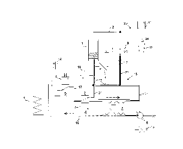
The hydraulic circuit shown in Figure 1 comprises a cold-water inlet 23
connected to a
piping 15 with a first feed pipe 16, a second feed pipe 17, a pump 5 to supply
pressurized water, a heater 4 for heating the water supplied by the pump 5, a
brewing
chamber 1, which is fillable with coffee powder, and a dispensing device 20
with an
outlet pipe 21 having an outlet 24. One end of the first feed pipe 16 is
connected to the
cold-water inlet 23 via the pump 5 and the other end of the first feed pipe 16
is
connected to the heater 4. The second feed pipe 17 is connecting the heater 4
and the
brewing chamber 1. Thus the piping 15 is fluidly connecting the pump 5, the
heater 4
and the brewing chamber 1 for conducting pressurized water into the brewing
chamber
1. The second feed pipe 17 is including a first valve 6, which is a 3-port/2-
way valve in
the embodiment shown in Figure 1. The first valve 6 is a directional control
valve, for
example a solenoid valve.
The piping 15 is further comprising a connecting pipe 18 connecting the first
feed pipe
16 and the second feed pipe 17. In the connecting pipe 18, a second valve 2 is
arranged.
8
CA 3010834 2018-07-09
In the embodiment shown in Figure I, the second valve 2 is a directional
control 3-
port/2-way valve. The connecting pipe 18 and the second valve 2 are building a
mixer,
by which heated water outgoing of the heater 4 can be mixed with cold water
supplied
by the first feed pipe 16. Since the temperature of the mixed water is lower
than the
temperature of the hot water heated in the heater 4, the mixer is acting as a
cooler,
which is cooling the heated water to a lower temperature. In order to cool the
water
heated in the heater 4, cold water supplied by the first feed pipe 16 is fed
through the
opened second valve 2 into the second feed pipe 17 for mixing with the heated
water
outgoing of the heater 4.
Directly downstream of the heater 4, a first temperature sensor 14 is arranged
in the
second feed pipe 16 for detecting the temperature of the outgoing water of the
heater 4.
A second temperature sensor 10 is arranged in the second feed pipe 16 directly
upstream
of the brewing chamber 1 for detecting the temperature of the water fed into
the
brewing chamber 1. The brewing chamber 1 is coupled with a portion sensor 9,
which is
determining the amount of coffee powder filled in the brewing chamber 1. A
third
temperature sensor 11 is arranged in the outlet pipe 21 for determining the
temperature
of the beverage.
A bypass pipe 22 is bypassing the brewing chamber 1 and is connecting the
second feed
pipe 17 with the outlet pipe 21. In the bypass pipe 22, a throttle valve 7 and
a bypass
valve 8 are arranged.
The beverage machine shown in Figure 1 is electronically controlled by a
control
system, which is programmed to control the machine as follows:
The control system is driving the speed of the pump 5 in order to create an
adjustable
water pressure, which can be adjusted in combination of the water temperature.
The
diagram Temperature / Pressure is related to the desired flavour of the
produced
beverage. The pump 5 is transporting the cold water from the cold-water inlet
23 under
the predefined pressure into the first feed pipe 16. Then the cold water goes
into the
9
CA 3010834 2018-07-09
heater 4. In the heater 4, the water will be heated to the programmed heating
temperature (which preferably is between 85 and 110 C, corresponding to the
standard
needed for brewing a coffee beverage). The first temperature sensor 14 detects
the
heating temperature of the water and the control system is controlling the
power of the
heater 4 to hold the temperature of the water heated in the heater 4 to the
predefined
temperature value.
Downstream of the heater 4, the first valve 6, when opened, allows the heated
water to
flow into the brewing chamber 1 and going therein through the coffee powder
and thus
is brewing the coffee powder. The brewed coffee is flowing out of the brewing
chamber
1 and into the outlet pipe 21 of the dispensing device 20. The dispensing
device 20 is
then discharging the brewed coffee beverage into a cup 12 standing underneath
the
outlet 24 of the dispensing device 20.
In this first mode of operation, the beverage machine is producing a hot
coffee
beverage. The second temperature sensor 10 here is detecting the water
temperature
streaming into the brewing chamber 1 and into the coffee powder and transfers
this
information to the control system, which monitors also the water temperature
inside or
directly downstream of the heater 4 using the first temperature sensor 14. The
control
system eventually will correct the reference heating temperature inside the
heater 4, in
order to maintain the programmed water temperature for brewing the coffee.
In a second mode of operation, the beverage machine is producing a cold coffee
beverage. In this second mode of operation, the second valve 2 is opened and
is
directing the cold water supplied by the first feed pipe 16 and the pump 5
directly into
the brewing chamber and through the coffee powder, without heating the water.
In a third mode of operation, the beverage machine is producing a warm coffee
beverage. In this third mode of operation, the first valve 6 and the second
valve 2 are
sequentially opened and closed, in order to mix cold and hot water. Thereby, a
predetermined water temperature being between the temperature of the cold
water
CA 3010834 2018-07-09
i
supplied by the pump 5 and the heated water supplied by the heater 4 can be
achieved,
depending on the on-/off-cycles of the first valve 6 and the second valve 2.
In each mode of operation, the brewed coffee is poured in the cup 12.
Supplementary,
by opening the bypass valve 8 hot, cold or warm clear water can be poured
inside the
cup 12, in order to modify the flavour profile of the produced beverage. The
third
temperature sensor 11 measures the temperature of the produced beverage poured
in the
cup 12. This temperature information of the third temperature sensor 11 is
processed by
the control system and depending on the flavour profile definition, the amount
of water
coming from the bypass 22 can be adjusted by the throttle valve 7. In every
case, when
the cup 12 is a PLA cup, the control system is stopping the discharge of
beverage by the
dispensing device 20, when the third temperature sensor 11 measures a
temperature of
the produced beverage of higher than 50 C.
The second embodiment of a beverage machine according to the invention shown
in
Figure 2 can be used with drinkable water or with water having no drinkable-
water
quality.
The hydraulic circuit of the second embodiment of a beverage machine shown in
Figure
2 also comprises a cold-water inlet 23 connected to a piping 15 with a first
feed pipe 16,
a second feed pipe 17, a pump 5 to supply pressurized water, a heater 4 for
heating the
water supplied by the pump 5, a brewing chamber 1 and a dispensing device 20
with an
outlet pipe 21 having an outlet 24. As in the embodiment of Figure 1, the
piping 15 is
fluidly connecting the pump 5, the heater 4 and the brewing chamber 1 for
conducting
pressurized water into the brewing chamber 1, with the second feed pipe 17
including a
first valve 6, which is a 3-port/2-way directional control valve. The
temperature sensors
10, 14 and 11, the pressure sensor 13 and the portion sensor 9 are the same as
in the first
embodiment of Figure 1.
11
CA 3010834 2018-07-09
1
In the second embodiment according to Figure 2, the cooler for cooling the
water heated
in the heater 4 is a heat exchanger 3, which is thermally coupling the first
feed pipe 16
and the second feed pipe 17. Therefore, a primary side of the heat exchanger 3
is
connected with the first feed pipe 16 and a secondary side of the heat
exchanger 3 is
connected with the second feed pipe 17. In the second feed pipe 17, upstream
of the heat
exchanger 3 and downstream of the first valve 6, a second valve 2 is arranged.
The
second valve 6 is a 3-port/2-way valve and can be a directional control valve
or a
proportional valve.
As in the embodiment of Figure 1, a bypass pipe 22 including a throttle valve
7 and a
bypass valve 8 is connecting the second feed pipe 17 and the outlet pipe 21
and is
bypassing the brewing chamber 1.
A further bypass pipe 24 is arranged in the circuit of the second embodiment
for
connecting an outlet of the second valve 2 with the second feed pipe 17 under
bypassing
the heat exchanger 3. With this further bypass pipe 24, water outgoing of the
heater 4
can be fed directly into the brewing chamber 1, without cooling the heated
water, when
the further bypass pipe 24 is opened by the second valve 2.
The beverage machine shown in Figure 2 is electronically controlled by a
control
system, which is programmed to control the machine as follows:
The cold-water inlet 23 is providing cold water, which can be non-potable
(impotable)
water in this case. The control system is driving the speed of the pump 5 in
order to
create an adjustable water pressure. The diagram Temperature / Pressure is
related to the
desired flavour of the produced beverage. The pump 5 is supporting the cold
water from
the cold-water inlet 23 under the predefined pressure into the first feed pipe
16 and into
the primary side of the heat exchanger 3. Downstream of the heat exchanger 3,
the cold
water goes inside the heater 4. In the heater 4, the water will be heated to
the
programmed heating temperature, which is at least 60 C and preferably is
between 85
and 110 C (corresponding to the standard needed for brewing a coffee
beverage). The
12
CA 3010834 2018-07-09
I
first temperature sensor 14 detects the heating temperature of the water and
the control
system is controlling the power of the heater 4 to hold the temperature of the
water
heated in the heater 4 to the predefined temperature value. By heating the
water in the
heater to temperatures above 60 C, viruses and bacteria present in the (non-
potable)
water are killed. The heated and thus sterilized water then can be used for
brewing
beverages with hot, cold or warm water, depending of the customer's choice, as
explained below.
Downstream of the heater 4, the first valve 6, when opened, and the second
valve 2
allows the heated water to flow directly into the brewing chamber 1 and going
through
the coffee powder for brewing it. In a first mode of operation, a hot coffee
beverage is
produced, by directing the heated water outgoing from the heater 4 by the
second valve
2 into the bypass pipe 24, which is bypassing the heat exchanger 3. From the
bypass
pipe 24, the hot water is flowing directly into the brewing chamber 1, without
being
cooled.
As in the first embodiment, the second temperature sensor 10 is detecting the
water
temperature coming inside the coffee powder and transfers this information to
the
control system, which monitors also the water temperature inside the heater 4
using the
first temperature sensor 14. The control system is controlling the power of
the heater 4,
in order to maintain the programmed heating temperature.
In a second mode of operation, the second valve 2 directs the heated water
coming from
the heater 4 into the secondary side of the heat exchanger 3. In the heat
exchanger 3, the
heated water outgoing of the heater 4 is cooled by thermal transfer with the
cold water
supplied by the first feed pipe 16 and flowing through the primary side of the
heat
exchanger 3. The heated water is cooled in the heat exchanger 3 to
temperatures in the
range of 20 C to 60 C, preferably below 50 C. Downstream of the heat exchanger
3,
the cooled water is directed into the brewing chamber 1, to produce a cold
coffee
beverage, having a product temperature at the outlet 24, which in either case
is below
13
CA 3010834 2018-07-09
I
50 C. The brewed beverage finally is poured into the cup 12, which then can be
a PLA
cup.
As in the first embodiment, supplementary hot or warm clear water can be
poured
through the bypass pipe 22 into the cup 12, when the bypass valve 8 is opened.
The
amount of the clear water poured into the cup 12 through the bypass pipe 22
can be
selected by the throttle valve 7. When the second valve 2 is directing the hot
water
directly into the bypass pipe 24 and from there into the bypass pipe 22, the
hot water is
not cooled, since the heat exchanger 3 is bypassed. In this case, hot water is
poured into
the cup, in addition to the coffee flowing out of the brewing chamber 1 and
the outlet
pipe 21. When the second valve 2 is directing the hot water into the heat
exchanger 3
and downstream of the heat exchanger 3 into the bypass pipe 22, the hot water
is cooled
in the heat exchanger 3 and is streaming as warm water into the cup 12. Also
in this
second mode of operation, the third temperature sensor 11 measures the
temperature of
the beverage poured in the cup 12, to ensure that a product temperature of 50
C will not
be exceeded.
The third embodiment of a beverage machine according to the invention shown in
Figure 3 is equivalent to the first embodiment, except the second valve 2,
which in the
third embodiment is a variable-flow valve, in particular a proportional valve.
The use of
a variable-flow valve has the advantage, that a fine-adjustment of the mixing
temperature of the mixed water can be made. The variable-flow valve 2 of the
third
embodiment enables to adjust the amount of cold water flowing from the first
feed pipe
16 through the second valve 2 into the second feed pipe 17. Thereby, the
mixing
temperature of the mixed hot and cold water can be adjusted to a temperature
value as
needed.
14
CA 3010834 2018-07-09