Note : Les descriptions sont présentées dans la langue officielle dans laquelle elles ont été soumises.
CA 03010877 2018-07-09
Plastic thread element and connection assembly consisting of a plastic support
part and a
plastic thread element
1. Field of the Invention
The present invention relates to a thread element made of plastic, in
particular a plastic screw, a
-- plastic thread bushing with an inner thread and a plastic thread insert, a
connection assembly
consisting of a plastic support part with a receiving opening, in which the
thread element has
been screwed while forming a thread in a self-acting manner, and a method for
manufacturing
the connection assembly from the at least one plastic support part and the
thread element made of
plastic, as well as a method for manufacturing the thread element.
2. Backround of the Invention
The above-mentioned connection assemblies consisting of at least one support
part made of
plastic and a plastic thread element in the form of a screw or a thread
bushing with a self-forming
outer thread are known in the prior art. They are described for example in DE
2 047 482 Al, US
4,637,767, US 5,921,735, US 5,385,439 and DE 10 2004 021 484 Al.
US 5,385,439 describes a screw, on the shaft of which an outer thread is
arranged. Form ele-
ments are provided on individual turns of the threading of this screw. These
form elements
extend in radial direction and/or axial direction beyond the geometric
dimensions of the adjacent
turn of the threading. In this way, they form a counter-thread, for example in
a support part,
particularly when the forming elements are arranged in the first turns near
the tip region of the
screw of the threading.
1
CA 03010877 2018-07-09
US 5,921,735 describes a screw, the shaft of which is also provided with an
outer thread. This
outer thread is characterized by four different thread zones distributed over
the length of the
screw on the shaft. By changing the cross-sectional form of the shaft and the
thread arranged on
it, a retaining zone, various thread forming zones as well as an alignment
zone within the outer
thread of the screw can be realized.
US 4,637,767 also describes a screw with an outer thread, wherein the
individual turns of the
threading are provided with cam-shaped radial cutting projections. These
projections support the
forming of a counter-thread into a component wall. At the same time, however,
these projections
lo also provide a rotation inhibition which supports the hold of the
screwed-in threaded element in
the support component. The circumferentially freely distributed protrusions
result in uneven
torsional loads over the length of the screw shaft during the screwing-in of
the thread element
into the support component. These different torsional loads can cause the
thread element to fail.
DE 2 047 482 also describcs a screw generating a thread. The screw shaft
comprises five
rounded corners into which the corresponding thread sections have been cut.
Five relieving
flattenings with incomplete threads are located between these thread sections.
At the angular
thread projections the thread has its full depth, while the depth in the flat
sections is substantially
lesser. The flattened relief areas between the corner areas with threads serve
to accommodate
abrasive material so that the screw can move freely.
DE 10 2004 021 484 Al describes a plastic thread element which comprises
cutting edges and an
adjacent chip flute. In order to create this specific cutting geometry of the
thread profile, the
thread element consists of several angular segments that are radially offset
from one another in
such a manner that respective adjacent angular segments form efficient cutting
edges in the
screwing-in direction. This means that the halves of the screw shaft or in
general of the outer
thread viewed in the axial sectional view are offset from one another in the
radial direction in
such a manner that the outer thread does not comprise a constant core
diameter. This offset
causes radially projecting cutting edges in the course of the thread or within
a turn, which form a
2
counter-thread in the support component. According to another alternative,
notches have been
cut from the circumferential turns of the threading so that their radial side
forms a cutting edge
for the forming of a counter-thread. However, this construction has the
disadvantage that the
screw-in torque is higher than the loosening torque due to the cutting edges
in the screwing-in
direction. Due to this constellation, a loosening of the thread element is
generally facilitated.
It is thus the object of the present invention to provide a thread element
with an outer thread, a
connection assembly consisting of at least one support part and this thread
element, and a
to manufacturing method for the connection, which, compared to the prior
art, provide an improved
ratio between screwing-in torque and loosening torque, an improved torque
course during
screwing-in of the thread element into a component opening, and a greater
tolerance between a
diameter of the thread element and a diameter of the component opening
receiving the thread
element.
3. Summary of the Invention
The above object is solved by a thread element made of plastic, a connection
assembly with at
least one support part made of plastic and the thread element, by a method for
manufacturing a
connection assembly of at least one support part made of plastic and a thread
element made of
plastic, as well as by a manufacturing method for a thread element made of
plastic. Advanta-
geous embodiments of the present invention as well as further developments
become apparent
from the following description, the accompanying drawings and the appending
claims.
In one aspect the invention concerns a thread element made of plastic
comprising an axial piece
having a central axis and a thread turn of an outer thread circulating around
the central axis in
several windings, wherein the outer thread is adapted to form a counter-thread
when being
screwed into a receiving opening of a support part made of plastic, wherein a
plurality of
adjacent windings are interrupted at least over a part region of the axial
piece by at least two chip
flutes ex-tending parallel to the central axis, so that each interrupted
winding comprises at least
3a
CA 3010877 2019-10-31
one cutting web and one inhibition web in which a radial extension of the
cutting web is greater
than a radial extension of the inhibition web, wherein a core thickness of the
axial piece perpen-
dicular to the central axis of the outer thread is constant at least in the
part region of the axial
piece outside the longitudinal flutes.
In another aspect the invention concerns a method for manufacturing a
connection assembly
comprising at least one support part made of plastic and a thread element made
of plastic, the
thread element of which has an outer thread and the support part of which has
a receiving
opening, wherein the method comprises the following steps:
a. axial screwing-in of the thread element into the receiving opening,
b. thereby forming a counter-thread in an inner wall of the receiving
opening by means of a
plurality of cutting webs in the outer thread, and
c. creating a press fit in the formed counter-thread by engagement of a
plurality of inhibi-tion
webs which comprise a smaller radial extension than the cutting webs and which
are arranged
separately from the cutting webs via a plurality of chip flutes.
The invention also comprises a method for manufacturing a thread element made
of plastic
comprising the following steps:
a. providing an injection mold formed complementary to the thread element,
wherein the
thread element comprises an axial piece having a central axis and a thread
turn of an outer thread
circulating around the central axis in several windings, and a plurality of
adjacent windings are
interrupted at least over a part region of the axial piece by at least two
chip flutes extending
parallel to the central axis, so that each interrupted winding comprises at
least one cutting web
and one inhibition web in which a radial extension of the cutting web is
greater than a radial
extension of the inhibition web, wherein a core thickness of the axial piece
perpendicular to the
3b
CA 3010877 2019-10-31
central axis of the outer thread is constant at least in the part region of
the axial piece outside the
longitudinal flutes,
b. injection molding the thread element and
c. demolding the thread element from the injection mold.
The inventive thread element made of plastic comprises an axial piece with a
central axis, and a
thread turn circulating around the central axis in several windings as an
outer thread. The outer
thread is adapted to form a counter-thread when screwed into a receiving
opening of a plastic
support part, wherein a plurality of adjacent windings are interrupted by at
least two chip flutes
running parallel to the central axis at least over a part region of the axial
piece, so that each
3c
CA 3010877 2019-10-31
CA 03010877 2018-07-09
interrupted winding comprises at least one cutting web and one inhibition web,
wherein a radial
extension of the cutting web is greater than a radial extension of the
inhibition web, and a core
thickness of the axial piece perpendicular to the central axis of the outer
thread is constant at
least in the part region of the axial piece outside of the longitudinal
flutes. According to a
preferred embodiment of the present invention, the cutting web and/or the
inhibition web have a
constant radius in their circumferential course. It is further preferred that
a radius of the cutting
webs and/or inhibition webs changes relative to the longitudinal direction of
the thread element.
In this way, the cutting depths of the cutting webs and/or the thickness of
the press fit of the
inhibition webs in the component can be specifically adjusted in relation to
the axial length of the
thread element. This allows a torsional load of the thread element to be
distributed in axial
direction onto the thread element.
The inventive thread element consists of plastic and is configured
specifically for being screwed
into plastic support parts. For this purpose, the outer thread of the thread
element is designed in
such a manner that it creates a matching counter thread in a receiving opening
of the support
part. According to different preferred embodiments of the present invention,
such thread ele-
ments made of plastic are designed as screws with a screw head and a screw tip
or as thread
bushings with an inner thread and the inventively preferred outer thread or
with a through bore
without thread or as thread bushings with any internal structure or as hollow
screws with the
inventi vely preferred outer thread, for example preferably as a compression
limiter.
The inventive thread element comprises a thread turn which extends in several
windings around
the central axis of the thread element along the axial piece, for example the
shaft of the screw.
Here, a winding describes a 3600 rotation of the thread around the central
axis of the thread
.. element. In order to create a matching counter-thread in the receiving
opening of the support part
made of plastic, at least a plurality of adjacently arranged thread turns are
subdivided into at least
two webs by chip flutes extending parallel to the central axis. These chip
flutes preferably reach
to the core thickness of the thread element, so that they subdivide the
respective winding into at
least two winding portions separated from each other. These winding portions
form at least one
4
CA 03010877 2018-07-09
cutting web and at least one inhibition web. The cutting web is characterized
in that it projects in
radial direction beyond the inhibition web. As the cutting web is preferably
positioned prior to
the inhibition web when viewed in the screwing-in direction of the thread
element, it pre-forms a
matching counter-thread in the support part made of plastic, while the
subsequent inhibition web
creates a matching press fit in the created counter-thread for fastening the
thread element. With
reference to the screwing-out direction of the thread element, the cutting
webs also preferably act
rotation inhibiting. In this way, they support the inhibition webs or
compression webs which are
equipped with a smaller diameter and engage elastically pushing into the pre-
grooved coils of the
counter-thread and in this way create a braking or inhibiting effect both
during the screwing-in
and the screwing-out of the thread clement out of the receiving opening of the
support part. With
regard to an advantageous screwing-in, it is preferred that a cutting
resistance of the cutting web
is set low and evenly. By this appropriate adjustment of the cutting
resistance, a torsional load of
the thread element is reduced. As the cutting web preferably removes material
from the support
part by cutting or scraping when the thread element is screwed into the
component opening or
when the matching counter-thread is created, this material is preferably
collected in the chip
flutes and discharged from the thread connection via the chip flutes. At the
same time, however,
it is also possible for material to be pushed on by the cutting webs without
obstructing the
creation of the matching counter-thread. Due to the constant core thickness,
the thread element is
formed preferably symmetrically apart from the cutting webs with a larger
radius.
According to the invention, an even number of chip flutes is preferred in the
thread element,
preferably two or four or six or eight chip flutes. These chip flutes extend
parallel to the central
axis of the axial piece as previously defined above. In accordance with the
number of chip flutes,
the respective winding is subdivided into a corresponding number of winding
sections. These
winding sections can be configured as a cutting web and/or inhibition web.
According to a further preferred embodiment of the present invention, the
thread element
comprises one, two or four cutting webs per winding, wherein in the case of
more than one and
an even number of cutting webs, these are arranged in pairs opposite one
another. It is further
5
CA 03010877 2018-07-09
preferred to arrange three cutting webs spaced apart evenly along the
circumference of the thread
element.
According to the number of chip flutes mentioned above, which subdivide each
respective
.. winding in corresponding winding sections, the number of cutting webs and
inhibition webs per
winding is adjustable. In this way it is possible to adapt the torsional load
of the thread element
to the plastic of the thread element and/or to the plastic of the support part
during rotation. If, for
example, the torsional load on the thread element increases too much with only
one cutting web
per winding, it is necessary to provide an additional cutting web per winding.
This cutting web
supports the forming of the counter-thread and at the same time the reduction
of the torsional
load of the thread element in order to allow the plastic thread element to be
screwed reliably and
undamaged into the support part. Accordingly, a number of optimally adapted
inhibition webs
per winding also ensures a sufficient and reliable support of the thread
element in the support
part through the compressive stresses induced at the inhibition web between
the support part and
the thread element.
According to a further preferred embodiment of the present invention, the
radial extension of the
cutting web is 0.1 to 0.5 mm greater than the radial extension of the
inhibition web of the
winding. This geometry and dimensioning of the cutting web ensures a
sufficient cutting effect
and thus creation of the counter-thread in the support part. Furthermore, this
dimensioning of the
cutting web realizes a suitable preparation of the counter-thread for the
press fit to be achieved
between the support part and the thread element by means of the subsequent
inhibition web. The
effect of the cutting web is preferably supported by the fact that the radial
outer side of the
cutting web is sharp-edged, preferably flattened or with an infinite radius of
curvature. Accord-
ing to another preferred embodiment, the effect of the inhibition webs is
supported by the
rounded radial outer side of the inhibition web.
According to another preferred embodiment of the present invention, the chip
flutes interrupt the
windings of the outer thread up to the core thickness of the thread element or
beyond. This
6
CA 03010877 2018-07-09
preferred depth of the chip flutes is intended on the one hand to provide
sufficient free space for
the receiving of removed material. Furthermore, the depth of the chip flutes
ensures that the
lateral areas of the cutting webs and inhibition webs oriented in the
circumferential direction of
the thread element are fully available for the engagement with the material of
the support part. In
this way, the cutting web preferably develops its maximum possible cutting or
notching or
grooving effect during the screwing-in. In the same way, these lateral end
faces of the cutting
web and the inhibition web also prevent unscrewing if the thread element is
loosened due to
external influences on the connection between the support part and the thread
element.
According to another preferred embodiment of the present invention, the
cutting web comprises
a circumferential extension with a starting point and an end point viewed in
the screwing-in
direction, wherein the radial extension of the cutting web is greater at the
starting point than the
radial extension of the cutting web at the end point. Due to this specific
dimensioning of the
cutting web, it comprises an inclination when viewed in the circumferential
direction. With
-- respect to turning the thread element in the screwing-out direction, the
cutting web in this way
develops a wedge effect which counteracts the screwing-out of the thread
element from a
receiving opening of the support part with inhibitory compressive stresses
especially between the
starting point of the cutting web and the wall of the counter-thread. It is
also preferred that the
radial extension of the cutting web is the same at the starting point and the
end point. According
.. to another preferred embodiment of the present invention, cutting webs with
a constant radius or
with different radii are arranged on the thread element. It is also preferred
to arrange inhibition
webs with a constant radius or with different radii on the thread element.
The present invention also comprises a connection assembly with at least one
support part made
of plastic and the thread element made of plastic described above, which is
screwed into a
receiving opening of the support part.
The present invention also comprises a method for manufacturing the connection
assembly from
at least one support part made of plastic and a thread element made of
plastic, preferably a thread
7
CA 03010877 2018-07-09
element according to the embodiments described above, wherein the thread
element comprises
an outer thread and its support part comprises a receiving opening. The method
comprises the
following steps: axially screwing the thread element into the receiving
opening, thereby forming
a counter-thread in an inner wall of the receiving opening by means of a
plurality of cutting webs
in the outer thread and creating a press fit in the formed counter-thread by
engagement of a
plurality of inhibition webs which have a smaller radial extension than the
cutting webs and
which are arranged separately from the cutting webs via a plurality of chip
flutes. This method is
preferably complemented by the removal of material abrasion via the chip
flutes, whereby the
material abrasion occurs during the forming of the counter-thread.
The present invention further comprises a manufacturing method for the thread
element made of
plastic, which comprises the following steps: providing an injection mold
formed complementary
to the thread element, wherein the thread element comprises an axial piece
having a central axis
and a thread turn of an outer thread rotating around the central axis in
several windings, and a
plurality of adjacent windings are interrupted at least over a part region of
the axial piece by at
least two chip flutes extending parallel to the central axis, so that each
interrupted winding
comprises at least one cutting web and one inhibition web in which a radial
extension of the
cutting web is greater than a radial extension of the inhibition web, wherein
a core thickness of
the axial piece perpendicular to the central axis of the outer thread is
constant at least in the part
region of the axial piece outside the longitudinal flutes, injection molding
the thread member and
demolding the thread member from the injection mold. For a more detailed
geometric design of
the injection mold, it is referred to the above explanation of the thread
element, as the injection
mold is preferably formed complementary to the geometric features of the
thread element
described there.
4. Short Description of the Accompanying Drawings
The present invention is described further with reference to the detailed
figures. It shows:
8
CA 03010877 2018-07-09
Fig. IA, fi a preferred embodiment (A) of an inventive plastic thread and (B)
of a thread
bushing or hollow screw with through bore,
Fig. 2 a side view of the screw from Fig. 1 A,
Fig. 3 a sectional view along the line 3-3 from Fig. 2,
Fig. 4 an axial sectional view of the preferred embodiment if the
inventive screw accord-
ing to Fig. 2 along the line 4-4,
Fig. 5 a bottom view of the preferred plastic screw according to Fig. 2,
Fig. 6 an axial sectional view along the line 6-6 from Fig. 5,
Fig. 7 a torque chart with preferred torque characteristics for screwing in
the thread-
forming plastic screw or the thread-forming thread element,
Fig. 8 a flow chart of a preferred embodiment of the inventive
connection method, and
Fig. 9 a flow chart of a preferred embodiment of the inventive
manufacturing method of
the thread element.
5. Detailed Descrtion of the Preferred Embodiments
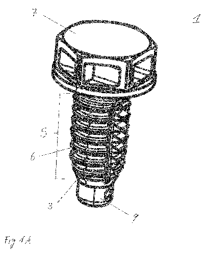
A preferred embodiment of the inventive thread element in form of a screw 1
made of plastic is
shown in Fig. 1 A. The thread element can preferably also be realized as a
thread bushing or
thread insert 2 made of plastic, as it is shown in Fig. 1 B.
An outer thread 5 of the plastic screw 1 or the plastic thread bushing 2 is,
according to the
invention, preferably constructed in such a way that when penetrating into a
receiving opening of
9
CA 03010877 2018-07-09
a support part, it forms a counter-thread in its internal wall in an optimal
manner. The counter-
thread can be formed by a cutting process or by material deformation or by a
combination of
both processes.
.. The inventively preferred screw 1, which is shown as an example in Fig. 1,
consists of a screw
shaft 3 with a solid core and the outer thread 5 with a single thread turn 6,
a screw head 7, a
transition area 8 between the screw shaft 3 and the screw head 7, a drive
means at the screw head
7 and a tip 9 at the end of the core or the screw shaft 3 of the screw 1
opposite to the screw head
7. In the following, the outer thread 5 of the thread element, for example the
screw 1 made of
.. plastic or the thread bushing 2 made of plastic, is described on the basis
of the screw 1. This
description also applies to the outer thread of the thread insert 2.
The outer thread 5 is formed on an axial piece 10 of the solid screw shaft 3
or on the radial outer
side of a hollow cylindrical thread insert 2 and thus of an axial piece 10
arranged there. It
extends parallel to the central axis M of the thread element. The thread turn
6 runs in a plurality
of windings 20 around the central axis M. A winding 20 denotes a convolution
with an angle of
360 about the central axis M. At least two chip flutes 50 extend parallel to
the central axis M
along the axial piece 10, wherein, according to a first preferred embodiment
of the present
invention, the axial piece 10 has a circular cross-section. According to the
different preferred
.. embodiments of the present invention, a plurality of chip flutes 50 is
provided, in particular two
or four or six or eight chip flutes.
The chip flutes 50 pass through the individual windings 20 of the thread turn
6. Preferably, the
chip flutes 50 have a radial depth up to a core thickness DK of the axial
piece 10 or deeper.
.. Accordingly, the windings 20 are completely missing in the area of the chip
flutes 50. Further-
more, the chip flutes 50 preferably comprise a width bsN in the
circumferential direction of the
thread element in the range of 0.5 mm < bsN < 5 mm, preferably bsN = 1.3 mm
for a preferred
double-edged thread and preferably bsN < 3 mm for a four-edged thread. This
ensures a suffi-
1 0
CA 03010877 2018-07-09
ciently large space to receive material abraded by the cutting webs 30 and/or
the inhibition webs
40 (see below).
The core thickness DK describes the thickness at the thread base of the screw
shaft or the thread
insert 2. This is usually referred to as a core diameter of the outer thread
5, provided that it is
arranged on a shaft 3 or a thread insert 2 with a circular cross-section
according to the first
preferred embodiment described above. In the ease of the present invention, it
is also preferred to
form the shaft of the screw 1 or the outer side of the thread insert 2 as an
orbiform curve which
has convex side areas in cross-section and is defined as a Reuleaux polygon.
The configuration
of cutting 30 and inhibition webs 40 explained in more detail below can be
realized on this basic
structure with a cross-section of the same thickness in the same way as on an
axial piece 10
being circular in cross-section.
The chip flutes 50 subdivide the plurality of windings 20 in the axial piece
10 into a plurality of
is axially spaced, section-wise circumferentially arranged and in axial
direction consecutive cutting
webs 30 and into a plurality of axially spaced and in axial direction
consecutive inhibition webs
40 (see Fig. 2). Since four chip flutes 50 are provided in the preferred
embodiment of Figures 2
to 4, the outer thread 5 preferably comprises two times a plurality of cutting
webs 30 and
inhibition webs 40 opposing one another in pairs. It is further preferred to
distribute the chip
flutes 50 to any circumference, so that the arrangement of the cutting 30 and
inhibition webs 40
is not symmetrical.
As can be seen from the radial sectional image in Fig. 3, a radial extension
of the cutting web 30
is greater than a radial extension of the inhibition web 40 in the same
winding 20. Preferably, the
cutting web 30 extends in the radial direction by a length in the range from
0.1 to 1.0 mm beyond
the radial extension of the inhibition web 40. According to a preferred
embodiment of the present
invention, the cutting web projects 0.35 mm per side in the radial direction
beyond the inhibition
web. Preferably, the projection length of the cutting web also increases with
an increasing
diameter of the thread element.
11
CA 03010877 2018-07-09
According to a further preferred embodiment of the present invention, the
cutting web 30 is
provided with a starting point 32 and an end point 34 when viewed in the
screwing-in direction
Re (see Fig. 5). In order to increase the cutting effect during screwing-in
and the inhibition
during screwing-out of the thread clement by the cutting web 30, the radial
extension of the
cutting web 30 is greater at the starting point 32 than at the end point 34.
Such a configuration
can also preferably be used with the inhibition web 40.
Regarding the end faces 32 of the cutting webs 30 in the axial sectional
images of Figures 4 and
6 as well as the end faces 42 of the inhibition webs 40 in the axial section
of Figure 6, it can be
seen as the preferred embodiment of the present invention that the radial
outer side of the cutting
webs 30 is formed with sharp edges. For this purpose, the cutting web 30 is
tapered radially on
the outer side to a tip (not shown). According to another embodiment, the
cutting web 30 is
flattened radially on the outer side, as shown in Figures 4 and 6. This sharp-
edged shape of the
radial outer side of the cutting webs 30 supports the cutting effect of the
cutting webs 30 in the
plastic of the support part when the counter-thread is created. It is further
preferred to form the
cutting webs 30 as well as the inhibition webs 40 rounded at the radial outer
side when viewed in
the axial sectional view. Preferably, the inhibition webs 40 are rounded with
a radius R40 = 0.25
mm. The radius is preferably in a range of 0.05 mm < R40 < 0.4 mm. The cutting
webs 30
preferably use the same radius or a flattening extending parallel to the
central axis M or an
infinite radius.
In the axial section, the flanks of the cutting webs 30 and of the inhibition
webs 40 preferably
include an angle in the range of 30 < < 40 , preferably a = 35 (see Fig. 6).
It is also pre-
ferred to form the cutting webs 30 with a larger flank angle cc than the
inhibition webs 40. This
supports and enhances the mechanical stresses between the formed counter-
thread and the flanks
of the inhibition webs 40, so that the inhibiting effect on the rotation of
the thread element is
increased.
12
CA 03010877 2018-07-09
Based on the geometry of the cutting webs 30 and the inhibition webs 40
described above, it is
apparent that the cutting webs 30 act as cutting edges in the plastic of the
support part in the
screwing-in direction R. If the thread clement is turned in the screwing-out
direction RA, the
cutting webs 30 have an inhibiting effect on the rotational movement due to
their radial exten-
sion and the preferred sharp-edged geometry. The compression webs 40 have a
preferably
elastically pressing effect in the pre-grooved coils of the counter-thread of
the support part. In
this way, they create an inhibiting effect in relation to the rotation of the
thread element, both in
the screwing-in direction RE and the screwing-out direction RA.
Subdividing the axial piece 10 into such webs 30, 40 over the entire length or
over a part of the
length of the outer thread 5 has a number of reasons. Due to the inventively
preferred construc-
tion of the outer thread 5, a cutting cutting web 30 is always followed by an
inhibiting inhibition
web 40 and then a cutting web 30, etc. This alternation preferably supports
the creation of the
counter-thread in the same way as a reliable support of the outer thread 5 by
press fit in the
support part. By means of the specifically arrangeable number and position of
the cutting webs
30 and the inhibition webs 40, force engagement points on the outer thread 5
are specifically
distributed during the screwing-in and screwing-out of the thread element into
the support part.
Since these force engagement points determine the torsional moment acting on
the thread
element in size and axial distribution, the mechanical load of the thread
element can be specifi-
cally adjusted via the arrangement of the cutting webs 30 and the inhibition
webs 40. In addition,
it is preferred to vary the axial piece 10 with cutting webs 30 and inhibition
webs 40 in its length,
to divide it into different length sections and/or to arrange only one or more
axial pieces 10
specifically relative to the length of the outer thread 5 at different axial
positions. In this way, the
thread element is adapted to a plastic of the support part and its material
properties and/or to a
geometry of the receiving opening for the thread element in the support part
and/or to a plurality
of support parts which are to be connected with only one thread element.
The thread element is made of a high-performance plastic with preferred high
temperature
resistance, high rigidity and high strength with low water absorption. With
regard to the extent of
13
CA 03010877 2018-07-09
these properties, there must be the greatest possible disparity from that of
the plastic of the
support part in order to achieve the desired form stability in the thread
profile and in the cutting
geometry for the cutability or formability for forming the counter-thread in
the support part.
Preferred high-performance plastics for the thread element are polyphthalamide
GF (PPA GF);
copolyamide based on polyphthalamide GF; polyetherimidc OF (PEI GF);
polyetheretherketone
OF (PEEK GF) and polyphenylene sulfide (PPS). The following materials can also
be consid-
ered: polyamide - high glass filled; polyphthalamide - carbon fiber
reinforced; polyphthalamide -
carbon fiber reinforced and glass fiber reinforced; copolyamide based on
polyphthalamide -
carbon fiber reinforced; copolyamide based on polyphthalamide - carbon fiber
reinforced and
glass fiber reinforced; duromer plastics. It is understood that these are only
preferred examples
for the material of the thread element, thus, other thermal high-performance
plastics can also be
used.
In order to create a connection assembly with at least one support part made
of plastic and an
above-mentioned thread element made of plastic, the following steps are
required: axially
screwing-in the thread element into the receiving opening in step Sl, thereby
forming a counter-
thread in an inner wall of the receiving opening by means of a plurality of
cutting webs 30 in the
outer thread in step S2, removing material abrasion via the chip flutes which
occurs during
forming of the thread in step S3 and creating a press fit in the formed
counter-thread by engage-
ment of a plurality of inhibition webs which have a smaller radial extension
than the cutting
webs and which are arranged separately to the cutting webs via a plurality of
chip flutes in step
S4.
With reference to Fig. 7, torque curves Ki to K3 are shown which characterize
the screwing-in of
a thread element, in this example a screw, into a support part. Curve Ki
describes the torque in
dependence on the rotation angle of the thread element with metric thread in a
metal-metal
connection. Due to the low friction during the screwing-in process, the curve
runs relatively flat.
In the area of the rise-jump of curve K1, the head of the thread element is
abutted on the support
part (head abutment). The area between the head contact and the fracture
torque of the thread
14
CA 03010877 2018-07-09
element in the maximum of curve Kt is relatively large due to the stability of
the metal. Curve K2
describes the screwing-in of a thread element made of plastic with the self-
forming thread
according to DE 10 2004 021 484 Al. Due to an increased torque in the area of
the head abut-
ment and a lower fracture torque compared to the metric thread of the metal-
metal connection of
curve Ki, the prior art self-forming thread demonstrates a limited practical
applicability. Curve
1(3 characterizes a preferred embodiment of the present invention. Due to the
form of the self-
forming thread, the torque has been reduced up to the head abutment. At the
same time, the range
of the tightening torque of the screw, that is, the range between head
abutment and fracture
torque. has been increased. As a result, the thread element can be tightened
with a lower proba-
bility of failure compared to the prior art.
It is inventively preferred that the thread element is manufactured by
injection molding. For this,
the following steps are provided: In a first step (H1), an injection mold is
provided, which is
formed complementary to the thread element. The thread element comprises the
form of one of
I 5 the above-mentioned preferred embodiments, which determines the
corresponding design of the
injection mold. In a subsequent step, the thread element is injection molded
(step H2) and is then
demolded from the injection mold (step 113).
CA 03010877 2018-07-09
List of Reference signs
1 screw
1' thread bushing or hollow screw
2 through bore
5 outer thread
6 thread turn
7 head
8 transition area
9 tip
10 axial piece
winding
cutting web
inhibition web
15 50 chip flute
DK core thickness
RE screwing-in direction
RA unscrewing direction
central axis
20 a flank angle
16