Sélection de la langue

Search

Sommaire du brevet 3012436 

Énoncé de désistement de responsabilité concernant l'information provenant de tiers

Une partie des informations de ce site Web a été fournie par des sources externes. Le gouvernement du Canada n'assume aucune responsabilité concernant la précision, l'actualité ou la fiabilité des informations fournies par les sources externes. Les utilisateurs qui désirent employer cette information devraient consulter directement la source des informations. Le contenu fourni par les sources externes n'est pas assujetti aux exigences sur les langues officielles, la protection des renseignements personnels et l'accessibilité.

Disponibilité de l'Abrégé et des Revendications

L'apparition de différences dans le texte et l'image des Revendications et de l'Abrégé dépend du moment auquel le document est publié. Les textes des Revendications et de l'Abrégé sont affichés :

  • lorsque la demande peut être examinée par le public;
  • lorsque le brevet est émis (délivrance).
(12) Brevet: (11) CA 3012436
(54) Titre français: PLANCHER D'INGENIERIE ET SYSTEMES D'ECHAFAUDAGE
(54) Titre anglais: ENGINEERED FLOOR AND SCAFFOLD SYSTEM
Statut: Accordé et délivré
Données bibliographiques
(51) Classification internationale des brevets (CIB):
  • E04G 1/00 (2006.01)
  • E04B 1/00 (2006.01)
  • E04F 15/00 (2006.01)
  • E04G 1/18 (2006.01)
  • E04H 15/00 (2006.01)
  • E04H 15/32 (2006.01)
  • E04H 15/56 (2006.01)
(72) Inventeurs :
  • FRANCIS, EINSTEIN B. (Etats-Unis d'Amérique)
(73) Titulaires :
  • BIL-JAX, INC.
(71) Demandeurs :
  • BIL-JAX, INC. (Etats-Unis d'Amérique)
(74) Agent: SMART & BIGGAR LP
(74) Co-agent:
(45) Délivré: 2022-06-21
(86) Date de dépôt PCT: 2016-08-16
(87) Mise à la disponibilité du public: 2017-02-23
Requête d'examen: 2020-11-11
Licence disponible: S.O.
Cédé au domaine public: S.O.
(25) Langue des documents déposés: Anglais

Traité de coopération en matière de brevets (PCT): Oui
(86) Numéro de la demande PCT: PCT/US2016/047116
(87) Numéro de publication internationale PCT: WO 2017031093
(85) Entrée nationale: 2018-07-24

(30) Données de priorité de la demande:
Numéro de la demande Pays / territoire Date
62/207,121 (Etats-Unis d'Amérique) 2015-08-19

Abrégés

Abrégé français

Le système de plancher modulaire unique à ossature formant un système d'échafaudage selon l'invention est un système d'ingénierie pouvant être utilisé avec la plupart des options offertes par les fabricants de tentes. Ledit plancher d'ingénierie est destiné à des tentes d'ingénierie à portée libre. Ce système unique transfère dans le sol, la charge de la tente, de l'armature de la tente, du système d'échafaudage et de l'ossature de plancher de la tente, par l'intermédiaire du montant de support de la tente. Ledit système est conçu de sorte que la partie de plancher ne supporte pas la tente, ni l'armature de tente, ni les mâts de tente, ni le système d'échafaudage.


Abrégé anglais


ABSTRACT
A scaffold apparatus may have a saddle with a platform and two sides
extending above the platform. The saddle may support one or two beams.
Date Recue/Date Received 2020-11-11

Revendications

Note : Les revendications sont présentées dans la langue officielle dans laquelle elles ont été soumises.


10
What is claimed is:
1. A scaffold apparatus, comprising: a saddle comprising a platform and two
spaced apart parallel sides extending above said platform; a beam having a
beam flange attached to an end portion of said beam; and an upright connector
comprising a bottom portion, said bottom portion having an insert, and a plate
attached above said bottom portion, wherein said upright connector insert is
located within said end portion of said beam and said beam flange is located
within said bottom portion of said upright connector adjacent said upright
connector insert.
2. The scaffold apparatus of claim 1, wherein said beam is received between
said two spaced apart parallel sides.
3. The scaffold apparatus of claim 1, wherein at least one mechanical fastener
connects said spaced apart sides to said beam and at least one mechanical
fastener connects said spaced apart sides to said bottom portion.
4. The scaffold apparatus of claim 1, wherein said beam flange is attached to
a
first side of an opening in said beam.
5. The scaffold apparatus of claim 1, wherein said insert is parallel but
spaced
apart from said beam flange.
6. The scaffold apparatus of claim 1, wherein said bottom portion is hollow.
7. The scaffold apparatus of claim 1, wherein said insert is attached to a
side of
an opening in said bottom portion.
8. The scaffold apparatus of claim 1, wherein an upright portion is connected
to
said plate.

11
9. The scaffold apparatus of claim 1, wherein said beam has a second end
portion with a second beam flange attached thereto.
10. The scaffold apparatus of claim 1, wherein said beam has at least one lip
for
supporting a platform flooring section.
11. The scaffold apparatus of claim 1, wherein a scaffold leg supports said
saddle.
12. A scaffold apparatus, comprising: a saddle comprising a platform and two
spaced apart parallel sides extending above said platform, a first beam and a
second beam, wherein a first flange is attached to an end of said first beam
and
a second flange is attached to an end of said second beam, wherein said first
flange is located within said second beam and said second flange is located
within said first beam adjacent said first flange, wherein said beams are
supported by said saddle.
13. The scaffold apparatus of claim 12, wherein both said first and second
beams are received between said two spaced apart parallel sides.
14. The scaffold apparatus of claim 12, wherein at least one mechanical
fastener
connects said spaced apart sides to said first and second beams.
15. The scaffold apparatus of claim 12, wherein said beam flanges are attached
to opposite sides of the respective beams.
16. The scaffold apparatus of claim 12, wherein each of said beams has at
least
one lip for supporting a platform flooring section.

12
17. The scaffold apparatus of claim 12, wherein a scaffold leg supports said
saddle.
18. The scaffold apparatus of claim 12, wherein said first flange is attached
to a
first end of said first beam and a second flange is attached to a second end
of
said first beam, and a first flange is attached to a first end of said second
beam
and said second flange is attached to a second end of said second beam,
wherein each of said first flanges are on opposite sides of said beams from
said
second flanges.
19. A scaffold apparatus, comprising: a first saddle comprising a platform
supporting two spaced apart parallel sides extending above said platform; a
first
beam and a second beam, wherein a first flange is attached to an end of said
first beam and a second flange is attached to an end of said second beam,
wherein said first flange is located within said second beam and said second
flange is located within said first beam adjacent said first flange, wherein
said
beams are supported by said saddle; and a second saddle comprising a platform
supporting two spaced apart parallel sides extending above said platform, an
upright connector comprising a hollow bottom portion supported by said second
saddle, a plate attached above said bottom portion and an upper geometric
portion attached above said plate, wherein a third flange associated with
either
said first or said second beam is located within said hollow bottom portion
and an
insert of said upright connector is located adjacent said third flange within
said
first or second beam.
20. The scaffold apparatus of claim 19, wherein said second saddle
simultaneously supports the beam associated with the third flange and the
upright connector.

13
21. An apparatus comprising a modular platform system with scaffold
understructure for supporting a tent and a tent frame wherein the apparatus
comprises more than one assembly of:
a scaffold leg having a ground end and a supporting end;
a saddle connected to the supporting end of a scaffold leg, wherein the saddle
engages and supports a first beam and a second beam;
wherein the first beam and the second beam have a flange attached to each end
of the first beam and each end of the second beam;
wherein the flanges of the first beam and the second beam are oriented such
that
the flanges of the first beam can be inserted into the second beam, without
creating a left beam and right beam;
wherein the first beam and the second beam are joined together at the saddle
by
inserting a flange of the first beam into the second beam and inserting a
flange of
the second beam into the first beam, resulting in the flange of the first beam
and
the flange of the second beam being adjacent;
wherein the first beam and the second beam have a shaped cross-section with
opposing lips configured to engage and support a platform flooring section;
and
an upright connector, having a flange, connected to at least one beam;
wherein the apparatus transfers the load from the tent to the ground through
the
upright connector, the beams, the saddle, and the scaffold leg.
22. The apparatus according to claim 21, wherein the upright connector further
comprises:
a bottom portion supported by the first beam;
a flat plate supported by the bottom portion; and
an upright portion supported by the flat plate, wherein the upright portion is
configured to engage a tent leg.
23. The apparatus according to claim 21, wherein the saddle further comprises
pin-snap lock shores for fastening the beams to the saddle.

14
24. The apparatus according to claim 22, wherein the upright portion is a
geometric projection.
25. The apparatus according to claim 21, wherein a multiplicity of the beams
and
the saddles can be arranged to accommodate a plurality of configurations.
26. An apparatus comprising a modular platform system with scaffold
understructure for supporting a tent and a tent frame wherein the apparatus
comprises more than one assembly of:
a scaffold leg having a ground end and a supporting end;
a saddle connected to the supporting end of a scaffold leg, wherein the saddle
engages and supports a first beam and a second beam;
wherein the first beam and the second beam have a flange attached to each end
of the first beam and each end of the second beam;
wherein the flanges of the first beam and the second beam are oriented such
that
the flanges of the first beam can be inserted into the second beam, without
creating a left beam and right beam;
wherein the first beam and the second beam are joined together at the saddle
by
inserting the flange of the first beam into the second beam and inserting the
flange of the second beam into the first beam, resulting in the flange of the
first
beam and the flange of the second beam being adjacent;
wherein one of the flanges of the second beam is inserted into the first beam
adjacent to the flange of the first beam; and
an upright connector, having a flange, capable of engaging a beam;
wherein the apparatus transfers the load from the tent to the ground through
the
upright connector, the beams, the saddle, and the scaffold leg.
27. The apparatus according to claim 26, wherein the first and the second beam
have a shaped cross-section with opposing lips; wherein the lips are
configured
to engage and support a platform flooring section.

Description

Note : Les descriptions sont présentées dans la langue officielle dans laquelle elles ont été soumises.


1
ENGINEERED FLOOR AND SCAFFOLD SYSTEM
TECHNICAL FIELD
A unique modular flooring system for clear span tents including system
scaffolding is described.
BACKGROUND
Conventional tent, awning and canopy frame structures that can be
assembled and disassembled are known. They are commonly made up of
cylindrical tubing and various types of junction elements or connectors, or so-
called slip fit or slip-on fittings, commonly termed corner, ridge
intermediate,
intermediate, three-way crown, four-way crown, six-way crown and eight-way
crown fitting.
Often, the prior art systems do not include means for sealing against the
weather and other environmental conditions at the joints where the various
panels are joined. Another disadvantage is that the prior art shelters have to
be
built on unlevel ground, which is the normal situation. Unlevel ground poses a
number of problems when a number of units have to be added to each other to
produce a relatively large shelter.
Another shortcoming is that the prior art systems are not strong enough to
support the tent and tent frame structure.
SUMMARY
The modular flooring system with scaffold understructure described herein
provides a solution to the problems of the prior art systems.
The system is capable of use with most clear span tent manufacturer's
structures.
Date Recue/Date Received 2020-11-11

2
Clear span tents and frame structures are designed and manufactured in
such a way that they can be assembled and disassembled at a site. The clear
span tent and structures are temporary structures and they are used in the
event
rental industries most of the time. The clear span tent and the frame
structures
are designed to be setup on a leveled surface. Most of the clear span tent
legs
(uprights) are pinned to a base plate and the base plates are secured to a
leveled surface. All of the base plates in a particular tent setup have to be
on the
same level. These base plates transfer the entire load from the tent to the
ground or to a floor where the base plates are secured.
In the majority of the time the clear span tents and frame structures are
not used on a leveled surface; instead they are used on an unleveled ground
like
golf courses. One or a few of the base plates may sit on the ground level but
the
rest of them are in a different elevation. In order to get a leveled surface
for the
base plates the customer has to create a platform. In the rental industry
there
are no engineered platforms designed to accommodate clear span tents and
structures. So the customers use different staging products or they create a
platform with scaffolding, wood and plywood.
The above mentioned poses the following challenges.
1. Safety of the tent platform.
2. These platforms are custom platforms and the load capacities of the
platforms are questionable.
3. Transferring the tent base plate reactions and the platform load to the
ground is questionable.
4. Most of the time there is no proper way securing the platform from uplift
loads.
5. No proper guide line to assemble a clear span tent on top of a platform.
Date Recue/Date Received 2020-11-11

3
The system described herein provides a solution for all the above challenges
because it is designed, engineered and manufactured to take different clear
span
tents and structures.
The engineered system solves many of the problems of prior art systems.
First, the sides of the tent extend outside and below beam connectors. The
enclosure system is economical and light weight in construction and provides
for
depositing rain water and snow on the ground outboard of the scaffold
assembly.
Secondly, the tent and tent frame are supported by scaffold legs which
support the engineered system. The platform does not support the tent and tent
frame. Instead, the platform transfers the live load to the system scaffold
legs.
The upright connecters also transfer (Upright) load to the system scaffold
leg.
The beam may also transfer loads (platform live load, load from the tent and
weight of the tent) to the system scaffold leg.
The tent floor can be 8 inches from the ground to 15 feet or even more
from the ground. As a result, this system may support a tent on very unlevel
ground. The load is transferred to the ground through the legs.
The components may be as follows: universal beam, upright connector,
beam connector, platforms, platform filler, universal saddle, and system
scaffolding under structure.
Other objects and advantages will become apparent to those skilled in the
art upon a review of the following detailed description of the preferred
embodiments and the accompanying drawings.
IN THE DRAWINGS
Fig. 1 shows one embodiment of a scaffold system without a platform.
Fig. 2 shows one embodiment of a universal beam in place on a saddle.
Fig. 3 shows one embodiment of an upright connector.
Date Recue/Date Received 2020-11-11

4
Fig. 4 shows one embodiment of clear span tent legs and platforms
(flooring) in place on the scaffold system of Fig. 1.
Fig. 5 shows one embodiment of a saddle.
Fig. 6 shows a side view of the saddle of Fig. 5.
Fig. 7 shows an end view of the saddle of Fig. 5.
Fig. 8 shows a side view of the universal beam.
Fig. 9 shows an end view of the universal beam.
Fig. 10 shows a side view of the upright connector of Fig. 3.
Fig. 11 shows an end view of the upright connector of Fig. 3.
Fig. 12 is a bottom view of the platform system shown in Fig. 4.
Fig. 13 shows one embodiment of a male roto lock used with the platform
system shown in Fig. 12.
Fig. 14 shows one embodiment of a female roto lock used with the
platform system shown in Fig. 13.
Fig. 15 shows the elevation of one embodiment of the system in greater
detail.
Fig. 16 is a top view of one embodiment of the universal beam.
Fig. 17 is a side view of one embodiment of the universal beam.
Fig. 18 shows one embodiment of a tent and tent frame supported.
Fig. 19 is an exploded view showing how one embodiment of a beam may
connect to one embodiment of a saddle.
Date Recue/Date Received 2020-11-11

5
Fig. 20 is an exploded view showing how one embodiment of an upright
connector may engage with one embodiment of a beam.
DETAILED DESCRIPTION
Described is an engineered flooring system for clear span tents and the
structures. The flooring system may have system scaffolding (under
structures),
and a flooring system. The understructure can be any system scaffolding as
long
as they have the right load capacity. Flooring systems may have the following
items: saddle, universal beam, platform, and upright connectors. The base
plates will be replaced by the upright connectors.
The upright connectors are specifically designed for tents so the customer
has to use the right upright connector for the right tent. The flooring system
accommodates most of the clear span tents and structures. When you use
different tents from different manufactures customers have to use the specific
upright connector for the specified tent. The universal beam, saddle and the
platforms are the same for any type of tent.
The flooring system is designed to transfer the entire load coming from the
platform and the tent; the load will be transferred to the scaffold legs. The
universal beam, saddle and the platform will transfer live load to the legs
and the
upright connector will transfer the tent load.
The other advantages of this system are the flooring system is designed to
go low as 8 inch elevation to any platform heights. Also, the tent platform
will be
the exact size of the tent so the platform will not stick outside the tent.
This
makes the tent floor water proof because when it rains, the water will flow
from
the wall to the ground not to the platform.
Date Recue/Date Received 2020-11-11

6
Fig. 1 shows one embodiment of a scaffold system without a platform.
Fig. 1 also shows scaffold system 10 including universal beam 12, upright
connector 14 and saddle 16.
Fig. 1 also shows conventional scaffold components. For example, Fig. 1
shows connecting devices 30, horizontal posts 32 and scaffold legs 34.
Fig. 2 shows the universal beam 12 in place on a saddle 16. Lips 11
support flooring sections 22.
Fig. 3 shows the upright connector 14. Upright connector 14 engages
universal beam 12. Also shown is upright portion 46 of upright connector 14
and
pin lock 35 of saddle 16. Also shown is beam 12 comprising bottom 74 and
sides 13.
As shown in Figs. 1 ¨ 3, the flooring system 10 is designed to transfer the
entire load coming from the platform and the tent to the scaffold legs.
Universal
beam 12, saddle 16, and the platform will transfer platform live load to the
legs.
Upright connector 14 will transfer the tent load to the scaffold legs.
Fig. 4 shows clear span tent legs and platforms (flooring) in place on the
scaffold system of Fig. 1. Fig. 4 shows clear span tent legs 20, and platforms
22.
Fig. 5 shows saddle 16. Saddle 16 includes insert, platform 33, and pin-
snap lock shores 35. Hex jam nut 36 and screw cap 38 also are shown. Also
shown is saddle 16 including platform 33 and sides 75. As can be appreciated
in
Figs. 5, 19 and 20, the beam 12 is received between sides 75.
Fig. 6 shows a side view of saddle 16 of Fig. 5.
Fig. 7 shows an end view of saddle 16 of Fig. 5.
Fig. 8 shows a side view of universal beam 12. Beam 12 also includes
flanges 50. Insert 49 is secured to upright connector 14 as shown in Figs. 10
and 11 with bolt 52 and nut 54.
Date Recue/Date Received 2020-11-11

7
As can be appreciated from Fig. 20, at least one mechanical fastener
connects the spaced apart sides 75 to the beam 12 and at least one mechanical
fastener connects the spaced apart sides 75 to a bottom portion 40 of the
connector 14.
Fig. 9 shows an end view of universal beam 12. From Fig. 9 it can be
appreciated that the flanges 50 are attached to a first side and a second side
of
an opening in the beam 12. From Fig. 20, it also be appreciated that the
insert
49 of connector 14 is parallel but spaced apart from the beam flange 50.
Fig 10 shows a side view of upright connector 14 of Fig. 3. Upright
connector 14 engages universal beam 12.
Connector 14 comprises the bottom portion 40 which circumscribes beam
12. Thus, as shown in Fig. 11, the bottom portion 40 may be hollow. It can
also
be seen that the insert 49 is attached to a side of an opening in the bottom
portion 40. Bolts with hex heads and lock nuts hold insert 49 in place. Screw
cap flat head sockets 42 also hold insert 49 in place. Connector 14 also
comprises flat plate 44 and upright portion 46.
Upright portion 46 engages clear span tent legs 20 as shown in Fig. 4. In
one embodiment, tent legs 20 circumscribe upright portion 46 and rests on flat
plate 44. The design of upright connector may vary depending on the design of
legs 20.
The upright connectors are specifically designed so the customer has to
use the right upright connector for the right tent. The flooring system
accommodates most of the clear span tents and structures. The universal beam,
saddle, and the platforms are same for any type of tent.
Fig. 11 shows an end view of upright connector 14 of Fig. 3. Housing 48
supports upright portion 46.
Date Recue/Date Received 2020-11-11

8
Fig. 12 is a bottom view of the platform system shown in Fig. 4. Male roto
locks 60 and female roto locks 62 also are shown.
Fig. 13 shows male roto lock 60 used with the scaffold system shown in
Fig. 12.
Fig. 14 shows female roto lock 62 used with the scaffold system shown in
Fig. 13.
Fig. 15 shows the scaffold system in greater detail. The platforms of Fig
12 are connected with another platform of the same size by roto lock. The roto
lock is not used to connect the platform to the beam. The lock underneath the
platform will secure the platform to the beam. Also shown is jack 73.
Every universal beam is connected with two universal saddles. Fig. 15
shows 4 universal beams. Other embodiments may include even more universal
beams connected together to form a chain. At the end you have two upright
connectors connected to the distal end and proximal end of the string.
Figs. 16 and 17 are views of the universal beam in greater detail. Inserts
50 may be welded to one side of beam 12 but preferably they are welded to
opposite sides of the beam 12. This makes the beam very special because you
eliminate left and right beams. One beam fit all sides.
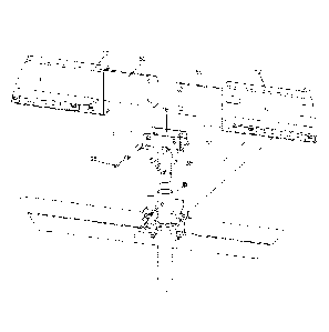
Fig. 18 shows a tent and tent frame. Shown are beam 12, connector 14,
tent legs 20, and scaffold legs 34. Portions of tent 75 are shown in phantom.
Fig. 19 is an exploded view showing scaffold legs 34 supporting saddles
16, saddles 16 support beams 12. Beams 12 include flanges 50. Fig. 19 also
shows a first flange 50 attached to an end of a beam 12 and a second flange 50
attached to an end of a beam 12. The first flange 50 is located within the
second
beam 12 and the second flange 50 is located within the first beam 12 so that
the
first and second flanges 50 are adjacent one another. Fig. 19 shows the beams
12 received between the sides of the saddle 16. Fig. 19 also shows at least
one
Date Recue/Date Received 2020-11-11

9
mechanical fastener connecting the sides of the saddle 16 with the beams 12.
Pin-snap lock shores 35 connect flanges 50 to saddle 16. Fig. 19 is an
exploded
view of Fig. 2.
Fig. 20 is an exploded view showing scaffold legs 34 supporting saddles
16, saddles 16 support beams 12, beams 12 support upright connectors 14 and
upright connectors 14 support tent legs 20, as shown in Fig. 4. Beams 12
include flanges 50. Pin-snap lock shores 35 connect flanges 50 to saddle 16.
Upright connector 14 engages beam 12. Bolts with hex heads and lock nuts hold
connector 14 in place on beam 12. Fig. 20 is an exploded view of Fig. 3.
The other advantages of this system are the flooring system is designed to
go low as 8 inch elevation to any platform heights. Also, the tent platform
will be
the exact size of the tent so the platform will not stick outside of the tent.
This
makes the tent floor water proof because when it rains, the water will flow
from
the wall to the ground not to the platform.
The above detailed description of the present invention is given for
explanatory purposes. It will be apparent to those skilled in the art that
numerous
changes and modifications can be made without departing from the scope of the
invention. Accordingly, the whole of the foregoing description is to be
construed
in an illustrative and not a limitative sense, the scope of the invention
being
defined solely by the appended claims.
Date Recue/Date Received 2020-11-11

Dessin représentatif
Une figure unique qui représente un dessin illustrant l'invention.
États administratifs

2024-08-01 : Dans le cadre de la transition vers les Brevets de nouvelle génération (BNG), la base de données sur les brevets canadiens (BDBC) contient désormais un Historique d'événement plus détaillé, qui reproduit le Journal des événements de notre nouvelle solution interne.

Veuillez noter que les événements débutant par « Inactive : » se réfèrent à des événements qui ne sont plus utilisés dans notre nouvelle solution interne.

Pour une meilleure compréhension de l'état de la demande ou brevet qui figure sur cette page, la rubrique Mise en garde , et les descriptions de Brevet , Historique d'événement , Taxes périodiques et Historique des paiements devraient être consultées.

Historique d'événement

Description Date
Paiement d'une taxe pour le maintien en état jugé conforme 2024-08-09
Requête visant le maintien en état reçue 2024-08-09
Inactive : Octroit téléchargé 2022-06-23
Lettre envoyée 2022-06-21
Accordé par délivrance 2022-06-21
Inactive : Page couverture publiée 2022-06-20
Inactive : Taxe finale reçue 2022-03-28
Préoctroi 2022-03-28
Inactive : Lettre officielle 2022-02-23
Lettre envoyée 2022-02-14
Un avis d'acceptation est envoyé 2022-02-14
Inactive : Approuvée aux fins d'acceptation (AFA) 2021-12-31
Inactive : Q2 réussi 2021-12-31
Exigences relatives à une correction du demandeur - jugée conforme 2021-01-28
Inactive : Lettre officielle 2020-12-02
Exigences relatives à la révocation de la nomination d'un agent - jugée conforme 2020-12-02
Inactive : Lettre officielle 2020-12-02
Lettre envoyée 2020-12-02
Exigences relatives à la nomination d'un agent - jugée conforme 2020-12-02
Exigences pour une requête d'examen - jugée conforme 2020-11-11
Toutes les exigences pour l'examen - jugée conforme 2020-11-11
Requête d'examen reçue 2020-11-11
Modification reçue - modification volontaire 2020-11-11
Demande de correction du demandeur reçue 2020-11-11
Demande visant la nomination d'un agent 2020-11-11
Demande visant la révocation de la nomination d'un agent 2020-11-11
Représentant commun nommé 2020-11-07
Inactive : COVID 19 - Délai prolongé 2020-08-06
Représentant commun nommé 2019-10-30
Inactive : Page couverture publiée 2018-08-03
Inactive : Notice - Entrée phase nat. - Pas de RE 2018-07-31
Inactive : CIB attribuée 2018-07-27
Inactive : CIB en 1re position 2018-07-27
Demande reçue - PCT 2018-07-27
Inactive : CIB attribuée 2018-07-27
Exigences pour l'entrée dans la phase nationale - jugée conforme 2018-07-24
Demande publiée (accessible au public) 2017-02-23

Historique d'abandonnement

Il n'y a pas d'historique d'abandonnement

Taxes périodiques

Le dernier paiement a été reçu le 2021-08-06

Avis : Si le paiement en totalité n'a pas été reçu au plus tard à la date indiquée, une taxe supplémentaire peut être imposée, soit une des taxes suivantes :

  • taxe de rétablissement ;
  • taxe pour paiement en souffrance ; ou
  • taxe additionnelle pour le renversement d'une péremption réputée.

Veuillez vous référer à la page web des taxes sur les brevets de l'OPIC pour voir tous les montants actuels des taxes.

Historique des taxes

Type de taxes Anniversaire Échéance Date payée
TM (demande, 2e anniv.) - générale 02 2018-08-16 2018-07-24
Rétablissement (phase nationale) 2018-07-24
Taxe nationale de base - générale 2018-07-24
TM (demande, 3e anniv.) - générale 03 2019-08-16 2019-07-30
TM (demande, 4e anniv.) - générale 04 2020-08-17 2020-08-07
Requête d'examen - générale 2021-08-16 2020-11-11
TM (demande, 5e anniv.) - générale 05 2021-08-16 2021-08-06
Taxe finale - générale 2022-06-14 2022-03-28
TM (brevet, 6e anniv.) - générale 2022-08-16 2022-08-12
TM (brevet, 7e anniv.) - générale 2023-08-16 2023-08-11
TM (brevet, 8e anniv.) - générale 2024-08-16 2024-08-09
Titulaires au dossier

Les titulaires actuels et antérieures au dossier sont affichés en ordre alphabétique.

Titulaires actuels au dossier
BIL-JAX, INC.
Titulaires antérieures au dossier
EINSTEIN B. FRANCIS
Les propriétaires antérieurs qui ne figurent pas dans la liste des « Propriétaires au dossier » apparaîtront dans d'autres documents au dossier.
Documents

Pour visionner les fichiers sélectionnés, entrer le code reCAPTCHA :


Pour visualiser une image, cliquer sur un lien dans la colonne description du document. Pour télécharger l'image (les images), cliquer l'une ou plusieurs cases à cocher dans la première colonne et ensuite cliquer sur le bouton "Télécharger sélection en format PDF (archive Zip)" ou le bouton "Télécharger sélection (en un fichier PDF fusionné)".

Liste des documents de brevet publiés et non publiés sur la BDBC .

Si vous avez des difficultés à accéder au contenu, veuillez communiquer avec le Centre de services à la clientèle au 1-866-997-1936, ou envoyer un courriel au Centre de service à la clientèle de l'OPIC.


Description du
Document 
Date
(aaaa-mm-jj) 
Nombre de pages   Taille de l'image (Ko) 
Dessins 2018-07-24 11 143
Revendications 2018-07-24 3 196
Abrégé 2018-07-24 2 76
Description 2018-07-24 7 603
Dessin représentatif 2018-07-24 1 28
Page couverture 2018-08-03 2 52
Description 2020-11-11 9 346
Abrégé 2020-11-11 1 5
Revendications 2020-11-11 5 205
Dessins 2020-11-11 14 360
Page couverture 2022-05-31 1 44
Dessin représentatif 2022-05-31 1 16
Confirmation de soumission électronique 2024-08-09 2 69
Avis d'entree dans la phase nationale 2018-07-31 1 193
Courtoisie - Réception de la requête d'examen 2020-12-02 1 434
Avis du commissaire - Demande jugée acceptable 2022-02-14 1 570
Certificat électronique d'octroi 2022-06-21 1 2 527
Traité de coopération en matière de brevets (PCT) 2018-07-24 9 605
Rapport prélim. intl. sur la brevetabilité 2018-07-24 9 566
Rapport de recherche internationale 2018-07-24 3 170
Demande d'entrée en phase nationale 2018-07-24 4 115
Déclaration 2018-07-24 1 48
Requête d'examen / Modification / réponse à un rapport 2020-11-11 51 1 662
Modification au demandeur-inventeur / Changement de nomination d'agent 2020-11-11 7 216
Courtoisie - Lettre du bureau 2020-12-02 1 188
Courtoisie - Lettre du bureau 2020-12-02 1 180
Courtoisie - Lettre du bureau 2022-02-23 1 152
Taxe finale 2022-03-28 4 118