Note : Les descriptions sont présentées dans la langue officielle dans laquelle elles ont été soumises.
SUB-SURFACE ELECTROMAGNETIC TELEMETRY SYSTEMS AND METHODS
Cross-Reference to Related Applications
[0001] This application claims priority from U.S. provisional application
number 62/297,691,
filed February 19, 2016, and U.S. provisional application number 62/299,872,
filed February 25,
2016.
Technical Field/Field of the Disclosure
[0002] The present disclosure relates generally to wellbore communications and
more
specifically to transmitting data between a downhole location and the surface
or between the
surface and a downhole location.
Background of the Disclosure
[0003] During a drilling operation, data may be transmitted from a downhole
transmitter located
on a downhole tool included as part of the bottom hole assembly (BHA) of a
drill string positioned
in a wellbore. Data transmitted from the downhole transmitter may include, for
instance, properties
of the surrounding formation, downhole conditions, status of downhole
equipment, orientation of
the downhole equipment, and the properties of downhole fluids. Electronics
present in the BHA
may be used for transmission of data to the surface, collecting data using
sensors such as vibration
sensors, magnetometers, inclinometers, accelerometers, nuclear particle
detectors, electromagnetic
detectors, and acoustic detectors, acquiring images, measuring fluid flow,
determining direction,
emitting signals, particles or fields for detection by other devices,
interfacing with other downhole
equipment, and sampling downhole fluids. The BHA may also include mud motors
and steerable
CA 3014061 2020-01-16
GA 03014061 2018-08-08
WO 2017/142937 PCT/US2017/017950
drilling systems, such as a rotary steerable system (RSS), which may be used
to steer the wellbore
as the wellbore is drilled. By receiving data from the BHA, an operator may
have access to the
data collected by the sensors.
[0004] The drill string can extend thousands of feet below the surface.
Typically, the bottom end
of the drill string includes a drill bit for drilling the wellbore. Drilling
fluid, such as drilling mud,
may be pumped through the drill string. The drilling fluid typically cools and
lubricates the drill
bit and may carry cuttings back to the surface. Drilling fluid may also be
used for control of bottom
hole pressure. In situations where the formation may be damaged by the
pressure generated by the
column of drilling fluid, mist or foam may be used to reduce the pressure on
the formation due to
the fluid column.
[0005] Examples of telemetry systems for transmitting data to the surface
include mud pulse (MP),
electromagnetic (EM), hardwired drill pipe, fiber optic cable, and drill
collar acoustic systems.
Traditionally, MP and EM telemetry may be less expensive to deploy than
hardwired drill pipe,
fiber optic cable and drill collar acoustic systems. An EM system may operate
when pumps are
not operating to circulate fluid through the drill string, which, in certain
operations, may be
necessary for use of MP systems. In certain traditional uses, an EM telemetry
system may transmit
data at a higher data rate compared to an MP system. EM systems may also
operate when foam
or mist are used as a drilling fluid which may hinder the generation or
reception of mud pulses of
sufficient amplitude for reliable MP telemetry. EM systems may be limited in
depth of reliable
operation due to attenuation of the signal received at surface, i.e., EM
signals, may be reduced to
an amplitude that is below the noise level generated by various pieces of
drilling equipment used
to drill the well.
2
GA 03014061 2018-08-08
WO 2017/142937 PCT/US2017/017950
Brief Description of the Drawings
[0006] The present disclosure is best understood from the following detailed
description when
read with the accompanying figures. It is emphasized that, in accordance with
the standard practice
in the industry, various features are not drawn to scale. In fact, the
dimensions of the various
features may be arbitrarily increased or reduced for clarity of discussion.
[0007] FIG. 1 is a schematic view of a drilling system consistent with
embodiments of the present
disclosure.
[0008] FIG. 2 is a schematic view of a drilling system consistent with
embodiments of the present
disclosure.
[0009] FIG. 3 is a schematic view of a drilling system consistent with
embodiments of the present
disclosure.
[0010] FIG. 4 is a schematic view of a drilling system consistent with
embodiments of the present
disclosure.
[0011] FIG. 5 is a schematic view of a drilling system consistent with
embodiments of the present
disclosure.
Summary
[0012] The present disclosure provides for a method. The method includes
drilling a section of a
first wellbore and casing a section of a first wellbore. The method also
includes lowering a
downhole receiving system into the first wellbore to a first wellbore depth
and drilling at least one
section of a second wellbore. In addition, the method includes positioning an
EM telemetry system
in the at least one section of the second wellbore and transmitting an EM
telemetry signal from the
3
EM telemetry system. The method also includes receiving the EM telemetry
signal with the
downhole receiving system.
[0013] The present disclosure provides for a system. The system includes a
downhole receiving
system positioned in a first wellbore at a first wellbore depth, the downhole
receiving system
suspended from a wireline. The wireline has a sheath and an insulated
conductor. The downhole
receiving system is configured to operate as an electrode. The system also
includes an uplink
receiver and an EM telemetry system positioned in a second wellbore. The EM
telemetry system
having an uplink transmitter, the uplink transmitter located at a second
wellbore depth.
[0014] The present disclosure provides for a method. The method includes
providing a
downhole receiving system, the downhole receiving system configured to operate
as an electrode.
In addition, the method includes suspending the downhole receiving system from
a wireline at a
first wellbore depth, the wireline having a sheath and an insulated conductor.
The method may
also include locating an uplink receiver at the surface, the uplink receiver
in electrical
communication with the downhole receiving system. In addition, the method
includes positioning
an EM telemetry system in a second wellbore, the EM telemetry system having an
uplink
transmitter, the uplink transmitter located at a second wellbore depth.
Further, the method includes
positioning a plurality of pairs of surface electrodes at the surface and
switching the uplink receiver
from a first pair of electrodes at the surface to a second pair of electrodes
at the surface, or from the
insulated conductor to one of a pair of the plurality of electrodes.
[0014a] The present disclosure provides for a method comprising: drilling a
section of a first
wellbore; casing a section of the first wellbore; lowering a downhole
receiving system into the first
wellbore to a first wellbore first depth, the downhole receiving system
including a centralizer
formed of conductive material; drilling a section of a second wellbore;
positioning an EM
telemetry system in the section of the second wellbore; transmitting an EM
telemetry signal from
4
CA 3014061 2020-01-16
the EM telemetry system; and receiving the EM telemetry signal with the
downhole receiving
system.
[0014b] The present disclosure provides for a system comprising: a downhole
receiving system
positioned in a first wellbore at a first wellbore depth, the downhole
receiving system suspended
from a wireline, the wireline having a sheath and an insulated conductor, the
downhole receiving
system configured to operate as an electrode, the downhole receiving system
including a centralizer
formed of a conductive material; an uplink receiver; and an EM telemetry
system positioned in a
second wellbore, the EM telemetry system having an uplink transmitter, the
uplink transmitter
located at a second wellbore first depth.
[0014c] The present disclosure provides for a method comprising: providing a
downhole receiving
system, the downhole receiving system configured to operate as an electrode,
the downhole
receiving system including a centralizer formed from a conductive material;
suspending the
downhole receiving system from a wireline at a first wellbore depth, the
wireline having a sheath
and an insulated conductor such that one or more contact points of the
centralizer are in electrical
connection with the wellbore; locating an uplink receiver at the surface, the
uplink receiver in
electrical communication with the downhole receiving system; positioning an EM
telemetry system
in a second wellbore, the EM telemetry system having an uplink transmitter,
the uplink transmitter
located at a second wellbore first depth; positioning a plurality of pairs of
surface electrodes at the
surface; and switching the uplink receiver from a first pair of electrodes at
the surface to a second
pair of electrodes at the surface, or from the insulated conductor and a
surface electrode to one of a
pair of the plurality of electrodes.
Detailed Description
[0015] It is to be understood that the following disclosure provides many
different embodiments,
or examples, for implementing different features of various embodiments.
Specific examples of
4a
CA 3014061 2020-01-16
GA 03014061 2018-08-08
WO 2017/142937 PCT/US2017/017950
components and arrangements are described below to simplify the present
disclosure. These are,
of course, merely examples and are not intended to be limiting. In addition,
the present disclosure
may repeat reference numerals and/or letters in the various examples. This
repetition is for the
purpose of simplicity and clarity and does not in itself dictate a
relationship between the various
embodiments and/or configurations discussed.
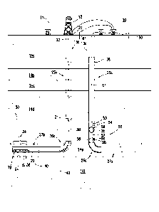
[0016] FIG. 1 depicts drilling site 10, where drilling system 11 may drill
multiple wellbores. In
certain embodiments, the wellbores may be drilled in succession, that is, a
first wellbore may be
drilled, followed later in time by a second wellbore and, in some embodiments,
by subsequent
wellbores. Drilling system 11 may include one or more drilling rigs 12 used to
drill, in succession,
a first wellbore 13a, a second wellbore 13b and, in certain embodiments,
additional wellbores
(such as, but not limited to, a third wellbore, fourth wellbore, etc.) at
drilling site 10. One or more
drilling rigs 12 may drill wellbores 13a and 13b through, for instance,
formations 14a, 14b, 14c,
14d and into target formation 14e located above formation 14f FIG. 1 depicts
wellbore 13b being
drilled with drill bit 19 positioned at bottom end 20 of drill string 21.
Drill string 21 is supported
at upper section 22 by drilling equipment 23. Drill bit 19 may be rotated by a
fluid motor, such as
mud motor 24. Drilling equipment 23 may pump fluid, such as drilling mud,
foam, or mist through
drill string 21 to drill bit 19, rotate drill string 21, raise and lower drill
string 21 within wellbore
13b, provide emergency pressure isolation in the event of a high pressure kick
encountered during
drilling such as performed by a blow out preventer (BOP), in addition to other
functions related to
drilling of wellbore 13b. Portions of drilling equipment 23 may be powered by
generator 29.
Wellbore 13a and 13b are shown as horizontal wellbores consisting of vertical
sections 25a and
25b, respectively, curve sections 26a and 26b, respectively and horizontal
sections 27a and 27b
respectively. Wellbores 13a and 13b are exemplary and one of ordinary skill in
the art with the
benefit of this disclosure will recognize that other configurations are
contemplated by this
disclosure. Wellbores 13a and 13b may be vertical wells, slant wells, S shaped
wells, multi-lateral
wells, or any other well shape known within the art. Wellbore 13a may be
configured differently
than wellbore 13b. FIG. 1 also depicts wellbores 13a and 13b as landing
horizontal sections, 27a
and 27b, respectively, into the same target formation 14e. In some embodiments
target formations
for wellbores 13a and 13b may differ.
[0017] FIG. I depicts wellbore 13a as having been drilled in its entirety,
extending through the
full range of horizontal section 27a. In some embodiments, wellbore 13a may be
only partially
drilled when drilling of wellbore 13b commences. For example, drilling rig 12
may successively
drill vertical section 25a and curve section 26a of wellbore 13a followed by
vertical section 25b
and curve section 26b of wellbore 13b followed by the vertical sections and
curve sections of any
additional wellbores drilled at drilling site 10. After drilling all vertical
sections and curve sections
for all of the vvellbores drilled at drilling site 10, drilling rig 12 may
successively drill horizontal
section 27a of wellbore 13a followed by horizontal 27b of wellbore 13b
followed by the horizontal
section of any other wellbores drilled at drilling site 10.
[0018] Drilling system 11 may include an EM telemetry system 30. EM telemetry
system 30
may include one or more uplink transmitters 32 located on BI-IA 34 for
transmitting an EM signal
to uplink receiver 36 located at the surface. In some embodiments, BHA 34
includes electric
current generator 38, which, causing current to flow within BHA 34 and drill
string 21 and into the
surrounding formations as depicted diagrammatically by lines of current 40.
Electrical current
generator 38 may be, for example and without limitation, an electrically
insulating gap across
which a voltage is impressed or a toroid for inducing currents within BHA 34
and drill string 21.
6
CA 3014061 2020-01-16
GA 03014061 2018-08-08
WO 2017/142937 PCT/US2017/017950
[0019] In the embodiment shown in FIG. 1, casing string 28 is installed in
wellbore 13a, referred
to herein as "casing" a wellbore. In certain embodiments, sections of wellbore
13a may be cased.
Casing string 28 may consist of multiple segments of conductive tubular pipe
of the same or
different diameters that may be cemented into wellbore 13a. Without being
bound by theory, the
lower resistance of casing string 28 as compared to the surrounding formations
may concentrate
the currents of EM telemetry system 30 due to the tendency for electrical
currents to take the path
of least resistance. Downhole receiving system 50 may be located within
wellbore 13a, suspended
on wireline 51 by wireline unit 52 located at the surface, for instance, to
locate downhole receiving
system 50 in depth proximity to EM telemetry system 30. Wireline unit 52 may
include equipment
for lowering downhole receiving system 50, such as winch and motor,
transmission equipment for
communicating data to uplink receiver 36 and a depth measurement system. Depth
proximity
refers to equipment at the same approximate depth from the surface. For
example, and without
limitation, when downhole receiving system 50 is in depth proximity to EM
telemetry system 30,
downhole hole receiving system 50 and EM telemetry system 30 may be within
1000 feet, 500
feet or 200 feet of the same depth from the surface. The depth proximity of
downhole receiving
system 50 to the source of the EM telemetry signal of EM telemetry system 30
and the current
concentrating effect of casing string 28 may operate to increase the signal
strength received by
downhole receiving system 50 as compared to the signal at surface. Such
positioning of downhole
receiving system 50 to the source of EM telemetry system 30 may allow the
receiving system to
operate reliably at greater depths than if the receiving system were located
at the surface.
[0020] In some embodiments, casing string 28 may include one or more sections
of non-
conductive tubular pipe. A non-conductive section of casing string 28 may
increase the resistance
across which an EM telemetry signal of EM telemetry system 30 may be received.
The non-
7
GA 03014061 2018-08-08
WO 2017/142937 PCT/US2017/017950
conductive section of casing string 28 may be made of, for example and without
limitation, carbon
fiber, or any other substantially non-conductive material with suitable yield
and tensile strength.
[0021] In some embodiments, wireline unit 52 may lower downhole receiving
system 50 to a depth
proximate uplink transmitter 32 of EM telemetry system 30 as drilling system
11 drills wellbore
13b. In such embodiments, the signal strength received at uplink receiver 36
may be increased by
following the progression of BHA 34 with downhole receiving system 50 as BHA
34 descends
into wellbore 13b. Operation of motors in wireline unit 52 to lower downhole
receiving system
50 into wellbore 13a may produce noise, which may corrupt a received signal,
i.e., the EM
telemetry signal received by downhole receiving system 50. In certain
embodiments, to reduce
the corruption of the received signal, the operation of lowering downhole
receiving system 50
within wellbore 13a may be performed at discrete depth intervals rather than
continuously.
Repositioning of downhole receiving system 50 may occur at intervals of
approximately 2000ft or
at intervals of approximately 1000ft or as little as approximately 200ft. Once
wireline unit 52 has
lowered downhole receiving system 50 to a depth at which the received signal
strength or signal
to noise ratio is observed to be near its maximum, motors and generators of
wireline unit 52 may
be turned off and a brake engaged to avoid inducing noise from the motors and
generators into the
received signal.
[0022] In some embodiments, wireline unit 52 lowers downhole receiving system
50 into wellbore
13a to a predetermined depth after which any additional length of wireline 51
may be cut off and
the portion left in wellbore 13a tied off at surface to suspend wireline 51
and downhole receiving
system 50 in wellbore 13a, thereby maintaining downhole receiving system 50 at
the
predetermined depth. In embodiments where downhole receiving system 50 is
lowered to a
predetermined depth, the received telemetry signal may be of lower amplitude
than embodiments
8
GA 03014061 2018-08-08
WO 2017/142937 PCT/US2017/017950
where wireline unit 52 lowers downhole receiving system 50 into wellbore 13a
so as to follow
uplink transmitter 32 as it descends wellbore 13b. However, cutting off the
excess length of
wireline 51 allows wireline unit 52 to be moved from drilling site 10 and used
in a different location
during drilling of wellbore 13b or any additional wellbores drilled at
drilling site 10. In some
embodiments, the predetermined depth selected for positioning of downhole
receiving system 50
may be based on the estimated depth at which the signal received across a pair
of surface electrodes
at uplink receiver 36 drops into the noise level making telemetry unreliable.
This determination
may be made, for instance during drilling of wellbore 13a, drilling of a
section of wellbore 13b, or
drilling of other wellbores at other drilling sites in the general
geographical location. The
predetermined depth at which downhole receiving system 50 is positioned may be
higher than the
estimated depth at which the signal is expected to become unreliable as
determined via the
aforementioned method to ensure adequate signal amplitude is received for
reliable telemetry. In
some cases, the depth at which downhole receiving system 50 is positioned is
between 100ft and
3500ft above the depth at which telemetry is expected to become unreliable and
in other cases the
depth is between 500ft and 2000ft above the estimated depth at which telemetry
is expected to
become unreliable. In other embodiments, the predetermined depth selected for
positioning of
downhole receiving system 50 may be based on a known location of a formation
of lower
resistivity than adjacent formations. Without being bound by theory, a
formation of lower
resistivity than adjacent formations may provide a comparatively low
resistance path for the signal
resulting in a significant reduction in signal strength above the low
resistivity formation.
Formations such as, for example, salt zones, water saturated zones, and sands
or sandstones with
clay minerals or pyrite may have low resistivities compared to other
formations. Knowledge of
the formation type or direct measurement of the resistivity obtained from
previous wells drilled in
9
the general geographic location, then, may be used to determine the
predetermined depth selected
for positioning of downhole receiving system 50. In some embodiments, downhole
receiving
system 50 may be positioned below or within known low resistivity formations
to increase the
received telemetry signal strength.
[0023] In other embodiments, the predetermined depth selected for positioning
downhole
receiving system 50 may be the approximate depth of horizontal section 27b of
wellbore 13b. In
yet other embodiments, the predetermined depth selected for positioning
downhole receiving
system 50 may be the approximate depth of curve section 26a for wellbore 13a
so that the force of
gravity acting upon downhole receiving system 50 operates to force contact of
the system with the
.. easing string 28 of wellbore 13a. In yet other embodiments, the
predetermined depth selected for
positioning downhole receiving system 50 may be the depth predicted by an
electro-magnetic
attenuation model to produce the highest received signal level by downhole
receiving system 50.
Non-limiting examples of electro-magnetic attenuation models can be found in
"Signal Attenuation
for Electromagnetic Telemetry Systems", SPE/IADC 118872, Schnitger, et al.
[0024] In some embodiments, wireline 51 may be a mono-conductor; the mono-
conductor may
include a center conductor, often consisting of multiple strands and described
hereinafter as an
"insulated conductor", an insulating layer and an outer conductive sheath. In
other embodiments,
wireline 51 may include an additional insulating layer over the outer
conductive sheath; the
additional insulating layer may reduce undesirable noise currents, such as
those generated by
.. drilling equipment, from conducting onto the sheath and coupling into the
insulated conductor of
wireline 51. In yet other embodiments, wireline 51 may be a multi-conductor
including multiple
insulated conductors surrounded by a conductive sheath that may be surrounded
by an additional
CA 3014061 2020-01-16
GA 03014061 2018-08-08
WO 2017/142937 PCT/US2017/017950
insulating layer. Wireline unit 52 may include a depth measurement system such
as, for example
a draw works encoder, for measuring the depth of downhole receiving system 50
within wellbore
13a. Downhole receiving system 50 may include cable head 53, which may connect
mechanically
to the sheath of wireline 51, thus providing a weight bearing connection to
downhole receiving
system 50. Cable head 53 may further provide an insulated electrical
connection to the insulated
conductor of wireline 51.
[0025] In an embodiment, downhole receiving system 50 may be configured to
operate as a single
down-hole electrode, conducting the telemetry signal from EM telemetry system
30 to uplink
receiver 36 at the surface. In such an embodiment, downhole receiving system
50 may include
shorting adapter 54 connected, such as by threadable connection, to cable head
53 and electrically
connecting the insulated conductor of wireline 51 to the body of shorting
adapter 54, thereby
shorting the insulated conductor of wireline 51 to downhole receiving system
50. In other
embodiments, electrical connection of the insulated conductor of wireline 51
may be made in cable
head 53, omitting shorting adapter 54. Wireline unit 52 may be configured with
cable head 53
providing an insulated connection to the insulated conductor of wireline 51;
however, use of
shorting adapter 54 may save time associated with re-heading the wireline to
short the insulated
conductor of wireline 51 to cable head 53. Downhole receiving system 50 may
further include
centralizers 55 and 56 and weight bar 57 all fabricated from a conductive
material such as, for
example steel or brass. Centralizers 55 and 56 and weight bar 57 may be
threadedly connected
end to end, forming a single conducting electrode. In certain embodiments, a
single centralizer
may be used, such as centralizer 55 or centralizer 56. In other embodiments,
centralizers 55 and
56 may be omitted. In yet other embodiments, weight bar 57 may be omitted. In
yet other
embodiments, shorting adapter 54 may be omitted.
11
GA 03014061 2018-08-08
WO 2017/142937 PCT/US2017/017950
[0026] Centralizers 55 and 56 may centralize the assembly within the cased
wellbore and provide
conductive contact from casing string 28 of wellbore 13a at contact points 58
to downhole
receiving system 50. Centralizers 55 and 56 are diagrammatically represented
as being of the leaf
spring type configured to position downhole receiving system 50 in the middle
of wellbore 13a
but may be configured to position downhole receiving system 50 against the
wall of casing string
28 in a "decentralized" configuration. Weight bar 57 adds weight to downhole
receiving system
50 for conveyance of the assembly to the desired downhole location within
wellbore 13a.
[0027] When configured as a downhole electrode, downhole receiving system 50
may conduct the
telemetry signal from EM telemetry system 30 at contact points 58 through the
insulated conductor
of wireline 51 to uplink receiver 36. Uplink receiver 36 may measure the
potential difference
between contact points 58 and a surface electrode. In some embodiments, ground
electrode 60
operates as a surface electrode. Ground electrode 60 may be connected to
uplink receiver 36 by
an insulated wire which may, in some embodiments, be shielded. In a non-
limiting embodiment,
ground electrode 60 may be a rod of conductive material such as, for example,
copper or iron. In
some embodiments, ground electrode 60 is positioned at a distance from
drilling equipment 23,
generator 29 and power cables connecting generator 29 to drilling equipment
23, which may
reduce received noise. The distance between ground electrode 60 and drilling
equipment 23,
generator 29 and the connecting power cables may be between approximately 50ft
and 5000ft or
between approximately 200ft and 100 Oft.
[0028] In another embodiment, the sheath of wireline 51 operates as a surface
electrode. In such
an embodiment, uplink receiver 36 is configured to measure the potential
difference between the
insulated conductor and conducting sheath of wireline 51. In some embodiments,
the insulated
conductor and sheath of wireline 51 are connected directly to the inputs of
uplink receiver 36. In
12
GA 03014061 2018-08-08
WO 2017/142937 PCT/US2017/017950
other embodiments, stranded or solid core wire may be used to connect the
insulated conductor
and sheath of wireline 51 to uplink receiver 36. In some embodiments, the
insulated conductor
and sheath of wireline 51 are connected to separate insulated conductors of a
twisted pair cable for
conducting the signal from wireline 51 to uplink receiver 36. In these
embodiments, improved
rejection of noise coupling into the signal through said cable may be
achieved. The sheath of
wireline 51 may be left ungrounded or attached via a wire to a ground stake
near the wellhead of
wellbore 13a or, preferably, located some distance away from drilling
equipment 23 to reduce
coupling of noise from the equipment into the sheath and from the sheath to
the insulated
conductor. The distance between the ground stake attached to the sheath of
wireline 51 and drilling
equipment 23 may be between SOft and 5000ft or between 200ft and 1000ft. In
other embodiments,
the top of the casing or wellhead of wellbore 13a operates as a surface
electrode and uplink receiver
36 is configured to measure the potential difference between the insulated
conductor of wireline
51 and the top of the casing or wellhead of wellbore 13a. In other
embodiments, part of drilling
equipment 23 operates as a surface electrode and uplink receiver 36 is
configured to measure the
potential difference between the insulated conductor of wireline 51 and part
of drilling equipment
23 such as, for example, the blow out preventer (BOP). In yet other
embodiments, the casing or
wellhead of another nearby wellbore operates as a surface electrode and uplink
receiver 36 may
be configured to measure the potential difference between the insulated
conductor of wireline 51
and the casing or wellhead of another nearby wellbore.
[0029] In some embodiments, uplink receiver 36 may be configured as a
switching mechanism to
switch between any pair of surface electrodes or the insulated conductor of
wireline 51 and any of
the surface electrodes described above. In such an embodiment, the switching
mechanism of
uplink receiver 36 may be an electronic switch, a mechanical switch, or a
patch panel or plug by
13
GA 03014061 2018-08-08
WO 2017/142937 PCT/US2017/017950
which an operator manually switches between wires. In such an embodiment,
uplink receiver 36
may switch between any pair of surface electrodes or the insulated conductor
of wireline 51 and
any of the surface electrodes described above so as to maximize the received
signal to noise ratio.
As a non-limiting example, when BHA 34 is drilling an upper portion of
vertical section 25b of
wellbore 13b, the largest signal to noise ratio may be received by configuring
uplink receiver 36
to switch to measuring the potential difference between ground electrode 60
and ground electrode
61. As BHA 34 drills into the curve, however, signal to noise ratio may be
maximized by
configuring uplink receiver 36 to switch to measuring the potential difference
between the
insulated conductor of wireline 51 and the sheath of wireline 51.
[0030] Referring now to FIG. 2, uplink receiver 36 may include a noise
cancellation system for
cancelling noise obtained from one or more noise sensors 62 employed to sense
noise generated
by, for example, motors used to raise or lower BHA 34 within wellbore 13b,
operate drilling fluid
pumps, rotate drill string 21, or other operations requiring electrical power
to drill wellbore 13b.
One non-limiting example of noise sensor 62 is a current sense coil. The
current sense coil may
consist of a coil wound around a rod shaped core of magnetic material such as,
for example iron
or permendur. The current sense coil may be placed adjacent and substantially
perpendicular to
one or more power cables supplying power from generator 29 to one or more
pieces of drilling
equipment 23. When current passes through power cables, a magnetic field may
surround the
cables. A portion of the magnetic field may pass through the magnetic core of
current sense coil,
which may induce a current in the coil of the current sense coil. The current
sense coil may further
include one or more resistors connected in series with the coil of the current
sense coil that may
operate to limit the induced voltage. Each end of the series arrangement of
coil and one or more
resistors of the current sense coil may be connected to two insulated wires,
preferably in twisted
14
GA 03014061 2018-08-08
WO 2017/142937 PCT/US2017/017950
pair arrangement, the ends of which may be connected to uplink receiver 36 as
diagrammatically
depicted in FIG. 2.
[0031] In another embodiment, a magnetometer with sensitive axis aligned
substantially
perpendicular to one or more power cables supplying power from generator 29 to
one or more
pieces or drilling equipment 23 may be used as noise sensor 62. Another non-
limiting example of
noise sensor 62 is a pair of electrodes such as, for example, ground
electrodes 63 and 64, which
may be of similar construction to ground electrodes 60 and 61, and may be
positioned near
generator 29, near the power cables connecting generator 29 to portions of
drilling equipment 23
or near drilling equipment 23. In certain embodiments, the measured noise
signal from ground
electrodes 63 and 64 may also include a portion of the telemetry signal from
EM telemetry system
30. In such embodiments, the process of cancelling noise from the received
telemetry signal using
the measured noise signal from ground electrodes 63 and 64 may result in a
reduction in amplitude
of the resultant noise cancelled telemetry signal, which may be undesirable
due to a resultant
decrease in signal to noise ratio. In some embodiments, ground electrodes 63
and 64 may be
moved in relation to one another, the upper section 22 of drillstring 21, and
generator 29 so as to
reduce the amplitude of the telemetry signal of EM telemetry system 30 present
in the measured
noise signal from ground electrodes 63 and 64 and maximize the amplitude of
the measured noise.
Without being bound by theory, the amplitude of the telemetry signal present
in the measured noise
signal may be reduced by positioning ground electrodes 63 and 64 approximately
equidistant
radially from upper section 22 of drillstring 21 due to the tendency for the
current of the telemetry
signal of EM telemetry system 30 to return to drillstring 21 in a
substantially radial direction. In
some embodiments, then, the movement of ground electrodes 63 and 64 in
relation to one another,
the upper section of 22 of drillstring 21 and generator 29 may be guided by
positioning ground
electrodes 63 and 64 first approximately equidistant radially from upper
section 22 of drillstring 21
and then adjusting from there so as to maximize the amplitude of the measured
noise and minimize
the amplitude of the telemetry signal of EM telemetry system 30 present in the
measured noise
signal.
[0032] In another embodiment, the sheath of wireline 51 may be used in
combination with one of
ground electrode 60, ground electrode 61, ground electrode 63, ground
electrode 64 or an electrode
attached to a portion of drilling equipment 23 such as, for example the BOP,
or an electrode
attached to the wellhead or casing of another nearby wellbore (not shown) as
noise sensor 62. In
yet other embodiments, any two of the aforementioned electrodes may be used as
noise sensor 62.
Uplink receiver 36 may be configured to simultaneously measure noise from two
or more noise
sensors as described above so that the measured noise from each noise sensor
may be cancelled
from the telemetry signal received via the aforementioned methods. Non-
limiting methods for
cancelling the noise may include use of an adaptive filter operating as a
noise cancellation filter as
described in "Noise cancellation using adaptive algorithms", International
Journal of Modern
Engineering Research (IJMER), Vol.2, Issue 3, May-June 2012, pp-792-795,
Chhikara, et al., or
use of an optimal or Weiner filter. In some non-limiting embodiments, multiple
adaptive or optimal
filters may be cascaded or run in parallel to perform noise cancellation of
more than one measured
noise signal.
[0033] In other embodiments, downhole receiving system 50 may include two or
more downhole
electrodes separated by lengths of insulated wireline. Referring now to FIG.
3, downhole receiving
system 50 may include two electrode assemblies 70 and 71 separated by wireline
segment 72.
Electrode assembly 70 may include cable head 73, downhole receiver 74,
centralizers 75 and 76,
power unit 77 and lower cable head 78, all of which may be threadedly
connected. Cable head 73
16
CA 3014061 2020-01-16
GA 03014061 2018-08-08
WO 2017/142937 PCT/US2017/017950
may mechanically connect to the sheath of wireline 51, thereby providing a
weight bearing
connection to downhole receiving system 50. Cable head 73 may further provide
insulated
electrical connections to the one or more insulated conductors of wireline 51,
which may be
electrically connected to downhole receiver 74. Centralizers 75 and 76
centralize the assembly
within the cased wellbore and provide a conductive contact from the casing of
wellbore 13a at
contact points 79 to downhole receiving system 50. Centralizers 75 and 76 are
diagrammatically
represented as being of the leaf spring type configured to position the
downhole receiving system
50 in the middle of the wellbore 13a but may be configured to position
downhole receiving system
50 against the wall of the casing of wellbore 13a in a "decentralized"
configuration. Power unit
77 provides power to downhole receiver 74. In one non-limiting embodiment,
power unit 77 is a
battery.
[0034] In another non-limiting embodiment, power unit 77 is a power supply
configured to convert
power provided by wireline unit 52 and conducted down wireline 51 to downhole
receiving system
50. Lower cable head 78 provides for mechanical and electrical connection to
wireline segment
72. VVireline segment 72 may electrically connect electrode assembly 71 to
electrode assembly
70. Wireline segment 72 may be of the mono-conductor or multi-conductor type
and may have an
insulated or non-insulated sheath. In yet another embodiment, wireline segment
72 may be
replaced by a tubular or string of tubulars through which one or more
insulated wires pass before
connecting to electrode assembly 71. In such an embodiment, the tubular string
may constructed
of conducting members or, in other embodiments, may include one or more
insulated members
providing an isolated gap so that the bodies of electrode assemblies 70 and 71
are electrically
isolated from one another except for the contact provided through casing
string 28. Electrode
assembly 71 may include cable head 53, shorting adapter 54, centralizers 55
and 56 and weight
17
GA 03014061 2018-08-08
WO 2017/142937 PCT/US2017/017950
bar 57 may be threadedly connected. Cable head 53 may connect mechanically to
the sheath of
wireline segment 72 and provide insulated electrical connections to the one or
more insulated
conductors of wireline segment 72 to shorting adapter 54. Shorting adapter 54
may short one or
more of the insulated conductors of wireline segment 72 to the body of
shorting adapter 54. In
some embodiments shorting adaptor 54, centralizers 55 and 56 and weight bar 57
may include
additional insulated wires passed through to the lower end of electrode
assembly 71 to allow for
connection of additional electrode assemblies in like manner so that the
insulated conductors of
wireline segment 72 each connect to a separate electrode assembly each
separated by a length of
wireline.
[0035] With continued referenced to FIG. 3, in an embodiment, downhole
receiver 74 may connect
electrically via separate insulated connections to electrode assembly 70 and
electrode assembly
71. Downhole receiver 74 may be adapted to measure the potential difference
between electrode
assembly 70 and electrode assembly 71. In such an embodiment, downhole
receiver 74 may
include electronics for filtering and amplifying the received telemetry
signal. In some
embodiments, downhole receiver 74 includes an automatic gain control circuit
(AGC) or a
programmable gain amplifier controlled by a micro-processor to adjust the gain
of the receiver.
The AGC or programmable gain amplifier may amplify the telemetry signal, in
certain
embodiments, without exceeding the output range of the amplifier. The filtered
and amplified
telemetry signal may be transmitted, such as by analog form, across the
insulated conductor and
sheath of wireline 51 when mono-conductor wireline is used or across two
insulated conductors of
wireline 51 when multi-conductor wireline is used. In some embodiments,
downhole receiver 74
includes an analog to digital converter (ADC). When an ADC is used, the
received telemetry
signal may be transmitted in digital form over wireline 51 to uplink receiver
36. In other
18
GA 03014061 2018-08-08
WO 2017/142937 PCT/US2017/017950
embodiments, the received telemetry signal may be transmitted up wireline 51
via an analog
modulation method such as amplitude modulation (AM), phase modulation,
frequency modulation
or other modulation methods known in the art.
[0036] In another embodiment, downhole receiver 74 may include an electronic
switch configured
to switch between the filtered and amplified signal, the insulated wire
connected to electrode
assembly 70, and the insulated wire connected to electrode assembly 71. When
an electronic
switch is used, downhole receiving system 50 may switch between operating as a
single electrode
system connecting either electrode assembly 70 or 71 to uplink receiver 36
through wireline 51 or
operating as two electrode system transmitting the filtered and amplified
potential difference
between electrode assemblies 70 and 71 to uplink receiver 36 through wireline
51. The switch
may be controlled by the micro-processor of downhole receiver 74 and may
switch from the
filtered and amplified potential difference between electrode assemblies 70
and 71 and the
insulated wire connected to electrode assembly 71 when the filtered and
amplified signal strength
drops below a pre-determined threshold. The predetermined threshold may be
between 0.1 uV
and 1mV or may be between luV and lOuV and will generally be set to a level
above the measured
noise floor of the filtering and amplifying electronics of downhole receiver
74.
[0037] With further reference to FIG. 3, in another embodiment, wireline 51 is
of the multi-
conductor type, containing two or more insulated conductors, with one
conductor electrically
connected to electrode assembly 70 and one conductor connected to electrode
assembly 71. In
such an embodiment, downhole receiver 74 and power unit 77 may be omitted. The
insulated
conductors of wireline 51 may conduct signals from electrode assemblies 70 and
71 to uplink
receiver 36. Uplink receiver 36 may be configured to measure the potential
difference between
the two electrodes. In another embodiment, uplink receiver 36 may be
configured to switch
19
GA 03014061 2018-08-08
WO 2017/142937 PCT/US2017/017950
between the wire connected to electrode assembly 70 or 71 and measure the
potential difference
between either the wire connected to electrode assembly 70 or 71 and one of a
ground electrode
60, the sheath of wireline 51, the casing or wellhead of wellbore 13a, a
portion of drilling
equipment 23 such as, for example, the BOP, or the casing of wellhead of
another nearby wellbore
(not shown). As BHA 34 descends wellbore 13b during the drilling operation,
uplink receiver 36
may switch between the wire connected to electrode assembly 70 and the wire
attached to electrode
assembly 71 so as to maximize the signal to noise ratio received. In such an
embodiment, it may
not be necessary to utilize wireline unit 52 for lowering a single electrode
into wellbore 13a to
maximize the signal to noise ratio received. In such an embodiment, the
switching mechanism of
uplink receiver 36 may be an electronic switch, a mechanical switch, or a
patch panel or plug
which an operator uses to manually switch between wires.
[0038] In the embodiment of FIG. 4, uplink receiver 36 may include a noise
cancellation system
for cancelling noise obtained from one or more noise sensors as previously
described. The noise
cancellation system may be used to cancel noise from the one or more telemetry
signals from the
one or more electrode assemblies of downhole receiving system 50.
[0039] In the embodiment of FIG. 5, uplink receiver 36 may be configured to
measure the potential
difference between contact points 58 to casing string 28 in wellbore 13a and
contact points 58c to
casing string 28c in wellbore 13c. Downhole receiving system 50c may be
suspended on wireline
51c from wireline unit 52. In such an embodiment, downhole receiving systems
50 and 50c may
each be configured to operate as a single down-hole electrode as described
above. Wireline unit
52 may be used to position, in sequence, downhole receiving system 50 and
downhole receiving
system 50c within wellbores 13a and 13c respectively. Any of the
aforementioned methods for
determining the depth of downhole receiving systems 50 and 50c may be used. In
the embodiment
of FIG. 5, uplink receiver 36 may include a noise cancellation system for
cancelling noise from one
or more noise sensors as described above. Use of downhole receiving systems 50
and 50c as a
single downhole electrode may improve signal to noise ratio as compared to a
single downhole
receiving system.
[0040] In another embodiment, uplink receiver 36 is configured to
simultaneously receive two or
more telemetry signals obtained via any of the aforementioned methods and may
combine the
telemetry signals via diversity combining methods such as, for example,
selection diversity,
maximal ratio combining, or other optimal combining methods as indicated in
"Performance
Analysis of Conventional Diversity Combining Schemes in Rayleigh Fading
Channel", "Eigen
Theory for Optimal Signal Combining: A Unified Approach", "Optimum Combining
in Digital
Mobile Radio with Cochannel Interference", "The Optimal Weights of A Maximum
Ratio
Combiner Using An Eigenfilter Approach".
[0041] In some embodiments, uplink receiver 36 includes one or more variable
resistors that may
be switched across any pair of inputs previously indicated so as to modify the
input resistance of
uplink receiver 36 which may in some cases improve received signal to noise
ratio. The variable
resistors may be of the manually controlled potentiometer type or a digitally
controlled resistor
which can be controlled by a processor. In such an embodiment, the variable
resistor switching
mechanism of uplink receiver 36 may be an electronic switch, a mechanical
switch, or a patch
panel or plug that an operator uses to manually switch the variable resistors
across any pair of
inputs previously indicated. Uplink receiver 36 may also include a passive
analog low pass or
band pass filter, a differential or instrumentation amplifier powered off of
an isolated power supply
the ground of which may be tied to one of the inputs, an isolation amplifier,
an automatic gain
control circuit or programmable gain amplifier, a 50 or 60Hz notch filter, and
an active band-pass
21
CA 3014061 2020-01-16
GA 03014061 2018-08-08
WO 2017/142937 PCT/US2017/017950
filter for each telemetry signal and noise sensor input. Uplink receiver 36
may also include one or
more analog to digital converters and one or more micro-processors and
associated memory, for
sampling the ADCs, controlling the programmable gain amplifiers and performing
digital filtering,
noise cancellation, and optimal combining of signals as have been described.
[0042] In some embodiments bi-directional communication may be achieved by
including a
transmitter at the surface which may use any of the aforementioned down-hole
electrode or surface
electrode configurations for transmitting down to a receiver incorporated into
EM telemetry
system 30.
[0043] The foregoing outlines features of several embodiments so that a person
of ordinary skill
in the art may better understand the aspects of the present disclosure. Such
features may be
replaced by any one of numerous equivalent alternatives, only some of which
are disclosed herein.
One of ordinary skill in the art should appreciate that they may readily use
the present disclosure
as a basis for designing or modifying other processes and structures for
carrying out the same
purposes and/or achieving the same advantages of the embodiments introduced
herein. One of
ordinary skill in the art should also realize that such equivalent
constructions do not depart from
the spirit and scope of the present disclosure and that they may make various
changes,
substitutions, and alterations herein without departing from the spirit and
scope of the present
disclosure.
22