Note : Les descriptions sont présentées dans la langue officielle dans laquelle elles ont été soumises.
CA 03014355 2018-08-13
ROCK DRILLING, SWELLING AND CHISELLING INTEGRATED
MACHINE BASED ON HIGH-PRESSURE FOAM MEDIUM
BACKGROUND OF THE INVENTION
TECHNICAL FIELD
The present invention belongs to the field of rock chiselling mechanical
technologies, relates to a rock chiselling integrated machine, and in
particular to, a
rock drilling, swelling and chiselling integrated machine based on a high-
pressure
foam medium.
BACKGROUND
The Thirteenth Five-Year Plan of China proposes that it is needed to improve a
proportion of non-fossil energy resources, and promote clean and efficient use
of
fossil energy resources such as coal, breakthroughs need to be obtained in
basic
theoretical researches and key technical problem resolving in safe development
of
coal resources in the deep part, environmental-friendly development of coal
resources
in the western region, clean and efficient use of coal, and the like; and a
safe technical
equipment level is greatly improved, and a progress in inspection on a hidden
disaster-causing factor is obtained. However, in a coal mining process, mining
proportion imbalance is always a main factor affecting a high yield and high
efficiency of a coal mine in China. As underground space development and
resource
mining in China continuously develop toward the deep part, a rock hardness
degree of
a tunneling working face is continuously increased, a rock blasting frequency
and
strength are both obviously increased, and safe problems are increasingly
prominent.
According to statistics, an amount of tunneling engineering of hard rock
(f>10)
roadways in only state owned coal mines is above 2000 km. In recent years, a
tunneling proportion of hard rock roadways is continuously increased and has
reached
approximately 1:3.1. Therefore, how to implement safe and efficient
construction of a
hard rock (F>10) tunneling working face is a problem or a difficult problem
that
urgently needs to be resolved. A mechanized tunneling method is an advanced
rock
roadway tunneling technology, but has an excessively high unit energy
consumption,
CA 03014355 2018-08-13
serious drill bit wear, and poor machine reliability and adaptability in a
hard rock
tunneling process, and is not suitable for opening a hard rock roadway.
Currently, in
hard rock roadway tunneling, a drilling and blasting method is mainly used, an
instant
blast is implemented by using dynamite, and its processes, such as rock
breaking,
waste stone exhausting, and shoring, need respective dedicated devices and are
restricted by an operation space and a working face. It is difficult to
implement
simultaneous and continuous tunneling. In addition, surrounding rocks are
severely
damaged. A mechanization degree is low and severely affects an objective of
safe and
efficient production. Meanwhile, labor intensity of workers is high, and dust
and
construction noise of devices affect health of operation personnel.
SUMMARY OF THE INVENTION
Technical problems: Objectives of the present invention are overcoming
disadvantages existing in the prior art, and providing a rock drilling,
swelling and
chiselling integrated machine based on a high-pressure foam medium that
integrates
rock chiselling, swelling, and cracking, that saves time and labor, and that
is efficient
and safe.
Technical solutions: The present invention provides a rock drilling, swelling
and
chiselling integrated machine based on a high-pressure foam medium, including
a
power apparatus, a drill pipe, a drill bit, a gear driving mechanism, and an
impact
piston, where: an interior of the drill pipe is provided with a central hole
in
communication with the drill bit, the drill pipe is provided with a high-
pressure foam
conveying apparatus, the gear driving mechanism and the impact piston are
disposed
on a rear part of the high-pressure foam conveying apparatus, and a hole
sealing
apparatus is mounted in a clamping manner on a front part of the high-pressure
foam
conveying apparatus;
the high-pressure foam conveying apparatus includes impact drill left and
right
pipe shells and a connection pipe connected between the impact drill left and
right
pipe shells and forming a high-pressure foam conveying chamber, where a
high-pressure foam conveying piston sleeved on the drill pipe is disposed
inside the
connection pipe, the impact drill left and right pipe shells are respectively
provided
with impact drill left and right pipe shell flow channels, outlets of the
impact drill left
and right pipe shell flow channels are in communication with a high-pressure
foam
2
CA 03014355 2018-08-13
generating and conveying system, and the drill pipe proximal to a side of the
right
shell is provided with a high-pressure foam conveying reserved hole;
the high-pressure foam generating and conveying system includes a one-way
valve, a pressurizer, a mixer, a gas pump, and an electromagnetic reversing
valve that
are sequentially connected by using a foam conveying pipeline, and a liquid
pump is
disposed on the mixer; and
the hole sealing apparatus includes a left fastener and a right fastener that
are
fastened on the drill pipe in a spaced manner and that are two opposite semi-
cylinders,
a steel wire expansion rubber tube is sleeved between the left fastener and
the right
fastener and the drill pipe, and the drill pipe between the left fastener and
the right
fastener is provided with a plurality of sealing reserved holes in
communication with
an inner hole of the drill pipe.
An outer diameter of the high-pressure foam conveying piston is provided with
a
high-pressure foam conveying piston shaft seal ring sealing an inner wall of
the
connection pipe, and an inner diameter is provided with a high-pressure foam
conveying piston hole seal ring sealing the drill pipe.
There are 2 to 4 high-pressure foam conveying reserved holes annularly
arranged.
There is a plurality of groups of sealing reserved holes disposed in a spaced
manner, and each group includes 2 to 4 holes annularly arranged.
A rock drilling, swelling and chiselling method of the foregoing rock
drilling,
swelling and chiselling integrated machine based on a high-pressure foam
medium
includes the following steps:
a. during rock drilling, swelling, and chiselling, starting a power apparatus,
where
the power apparatus actuates an impact piston to reciprocate at a high speed,
to enable
the impact piston to impact a drill pipe to implement impact movement of the
drill
pipe, meanwhile, a motor actuates a gear driving mechanism to move, a small
gear in
the gear driving mechanism drives a large gear, actuates the drill pipe to
rotate, and
drives the large gear to connect in a fitting manner to the drill pipe through
a spline, to
implement a rotation process of the drill pipe 3, and under the combined
action of
impact and rotation, the rock drilling, swelling and chiselling integrated
machine
drills a hole in a rock;
3
CA 03014355 2018-08-13
b. after the hole is completely drilled, conveying a gas and a liquid
respectively
through a gas pump and a liquid pump to a mixer to mix them, and after
pressurization is performed by using a pressurizer, generating high-pressure
foam
used for swelling and cracking the rock;
c. opening electromagnetic reversing valve, where the gas pump conveys the gas
along a left shell flow channel to a left-side chamber of the high-pressure
foam
conveying chamber, to push a high-pressure foam piston to move to the right,
and
after the high-pressure foam piston moves to the right side of the high-
pressure foam
conveying chamber, the electromagnetic reversing valve is closed;
d. conveying the high-pressure foam through a conveying pipeline to a right
shell
flow channel, to enter the high-pressure foam conveying chamber, where the
high-pressure foam conveying piston moves to the left under the action of the
high-pressure foam, the high-pressure foam enters a central hole of the drill
pipe from
a high-pressure foam conveying reserved hole of the drill pipe and moves to a
drill bit
along the central hole of the drill pipe, and in the moving process of the
high-pressure
foam in the central hole of the drill pipe, a part of the high-pressure foam
flows out
from a sealing reserved hole and forms an extrusion action on a steel wire
expansion
rubber tube of a hole sealing apparatus, after expansion, the extruded steel
wire
expansion rubber tube is tightly close to a wall of the drill hole, to achieve
a sealing
effect, and the other part of the high-pressure foam flows from a head
aperture of the
drill bit to the bottom of the hole; and
e. continuously injecting the high-pressure foam, so that the high-pressure
foam
concentrates at the bottom of the hole to form a high-pressure sealed area,
and the
rock is swelled and cracked under the action of the high-pressure foam, where
after
the rock is swelled and cracked, the right side of the high-pressure foam
conveying
chamber changes from a high-pressure area to a low-pressure area, and at this
time,
the left side of the high-pressure foam conveying chamber changes from a
low-pressure area to a high-pressure area, the high-pressure foam piston is
pushed to
an initial position, and one swelling and cracking period ends.
The gas pump and the liquid pump respectively convey different gases and
different liquids, and a ratio of the different gases to the different liquid
is 3:1.
Beneficial effects: Because the foregoing technical solutions are used, the
rock
4
CA 03014355 2018-08-13
drilling, swelling and chiselling integrated machine based on high-pressure
foam
medium provided by the present invention integrates rock chiselling, swelling,
and
cracking, utilizes a rock chiselling machine to open a hole to form a free
face,
expands, by means of a fracturing action of the high-pressure foam, internal
fissures
of rocks, reduces mechanical performance of the rocks, and cracks the rocks,
and not
only has features of improving opening efficiency of a hard rock roadway and
reducing labor intensity of workers, but also has features such as improving
safety of
a working environment. Continuous drilling and swelling operation of a
drilling rock
chiselling machine can be implemented, a working time of hole drilling, hole
sealing,
swelling, and cracking of the drilling rock chiselling machine is greatly
reduced,
working efficiency of the drilling rock chiselling machine is efficiently
improved,
opening efficiency of a hard rock roadway and safety of a working environment
are
improved, and labor intensity of workers is reduced. The machine has a simple
structure, convenient operation, and a good use effect, and is widely
applicable.
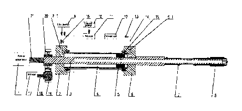
BRIEF DESCRIPTION OF THE DRAWINGS
FIG. 1 is a schematic structural diagram of the present invention;
FIG. 2 is a half-sectional view of a high-pressure foam conveying chamber in
the
present invention;
FIG. 3 is a partially enlarged view of a high-pressure foam conveying piston
sealing structure in the present invention; and
FIG. 4 is a half-sectional view of a hole sealing apparatus in the present
invention.
In the figures: 1-power apparatus; 2-impact drill pipe left shell; 2-1-left
shell flow
channel; 3-drill pipe; 3-1-high-pressure foam conveying reserved hole; 3-2-
sealing
reserved hole; 4-high-pressure foam conveying chamber; 5-high-pressure foam
conveying piston; 5-1-high-pressure foam conveying piston shaft seal ring;
5-2-high-pressure foam conveying piston hole seal ring; 6-impact drill pipe
right shell;
6-1-right shell flow channel; 7-hole sealing apparatus; 7-1-left fastener; 7-2-
steel wire
expansion rubber tube; 7-3-right fastener; 7-4-fastener fitting bolt hole; 7-5-
drill bit
tail sealing fastener end seal ring; 8-drill bit; 9-gas pump; 10-liquid pump;
11-mixer;
12-pressurizer; 13-one-way valve; 14-high-pressure foam conveying pipeline;
CA 03014355 2018-08-13
15-high-strength bolt; 16-electromagnetic reversing valve; 17-motor; 18-motor
output
shaft; 19-driving small gear; 20-driving large gear; 21-impact piston.
DETAILED DESCRIPTION OF THE INVENTION
The present invention is further described below with reference to embodiments
in the accompanying drawings.
As shown in FIG. 1, FIG. 2, and FIG. 3, the present invention provides a rock
drilling, swelling and chiselling integrated machine based on a high-pressure
foam
medium, including a power apparatus 1, a drill pipe 3, a drill bit 8, a gear
driving
mechanism, and an impact piston 21, where: an interior of the drill pipe 3 is
provided
with a central hole in communication with the drill bit 8, the drill pipe 3 is
provided
with a high-pressure foam conveying apparatus, the gear driving mechanism and
the
impact piston 21 are disposed on a rear part of the high-pressure foam
conveying
apparatus, and a hole sealing apparatus 7 is mounted in a clamping manner on a
front
part of the high-pressure foam conveying apparatus.
The power apparatus 1 includes a hydraulic pump, a cylinder, and a reversing
valve, is connected to the impact piston 21 through a piston lead sleeve, and
pushes
the impact piston 21 to produce a high-speed reciprocating impact effect.
The gear driving mechanism includes a motor 17, a motor output shaft 18, a
driving small gear 19 disposed on the motor output shaft 18, and a driving
large gear
20 engaged with the driving small gear 19, where the driving large gear 20 is
fixed on
the drill pipe 3.
The drill pipe 3 is under the combined action of engagement and driving of the
driving small gear 19 and the driving large gear 20 actuated by the impact
piston 21
and the motor shaft 18. The impact piston 21 implements high-speed
reciprocation
under the action of the power apparatus 1 to push the drill pipe to produce an
impact
effect. The motor 17 actuates the gear driving mechanism, the large gear 19
fits the
drill pipe through a spline, and the large gear 19 rotates to actuate the
drill pipe 3 to
implement rotation. A hole is drilled in an impacting manner on a rock whose
working face is swelled and cracked by using high-pressure foam, to form a
swelling
and cracking pre-drilled hole of the high-pressure foam.
The high-pressure foam generating and conveying system includes a one-way
6
CA 03014355 2018-08-13
valve 13, a pressurizer 12, a mixer 11, a gas pump 9, and an electromagnetic
reversing
valve 16 that are sequentially connected by using a foam conveying pipeline
14, and a
liquid pump 10 is disposed on the mixer 11. Gas-liquid mixing of different
proportions is implemented by adjusting conveying flow rates of the gas pump 9
and
the liquid pump 10. A gas pump conveying pipeline, a liquid pump conveying
pipeline, a pressurizer pipeline, and a high-pressure foam conveying pipeline
to left
and right shell flow channels 2-1 and 6-1 are all provided with a one-way
valve. The
gas pump 9 is separately to the mixer 11 and the left shell flow channel 2-1
through
pipelines, the liquid pump 10 is connected to the mixer 11. After the gas pump
9 and
the liquid pump 10 respectively convey a gas and a liquid to the mixer 11, and
mixed
foam is pressurized by using the pressurizer 12, the mixed foam is conveyed to
the
right shell flow channel 6-1.
The high-pressure foam conveying apparatus includes impact drill left and
right
pipe shells 2, 6 and a connection pipe connected between the impact drill left
and
right pipe shells 2, 6 and forming a high-pressure foam conveying chamber 4,
where a
high-pressure foam conveying piston 5 sleeved on the drill pipe 3 is disposed
inside
the connection pipe. An outer diameter of the high-pressure foam conveying
piston 5
is provided with a high-pressure foam conveying piston shaft seal ring 5-1
sealing an
inner wall of the connection pipe, and an inner diameter is provided with a
high-pressure foam conveying piston hole seal ring 5-2 sealing the drill pipe
3. The
impact drill left and right pipe shells 2, 6 are respectively provided with
impact drill
left and right pipe shell flow channels 2-1 and 6-1, outlets of the impact
drill left and
right pipe shell flow channels 2-1 and 6-1 are in communication with a high-
pressure
foam generating and conveying system, and the drill pipe 3 proximal to a side
of the
right shell is provided with a high-pressure foam conveying reserved hole 3-1.
There
are 2 to 4 high-pressure foam conveying reserved holes 3-1 annularly arranged.
The
connection pipe of the high-pressure foam conveying chamber 4 is connected to
the
impact drill pipe left shell 2 and the impact drill pipe right shell 6 through
high-strength bolts 15. Under the action of the bolt 15, the impact drill pipe
right shell
is tightly close to a left-side machining protrusion of the drill pipe 3.
As shown in FIG. 4, the hole sealing apparatus 7 includes a left fastener 7-1
and a
right fastener 7-3 that are fastened on the drill pipe 3 in a spaced manner
and that are
two opposite semi-cylinders used for sealing the bottom of a drill hole, the
left
7
CA 03014355 2018-08-13
fastener 7-1 and the right fastener 7-3 that are two opposite semi-cylinders
are
separately provided with a fastener fitting bolt hole. Two ends of the left
fastener 7-1
and the right fastener 7-3 abutted against a groove of the drill pipe 3 are
separately
provided with a drill bit tail sealing fastener end seal ring 7-5. A steel
wire expansion
rubber tube 7-2 is sleeved between the left fastener 7-1 and right fastener 7-
3 and the
drill pipe 3, and the drill pipe 3 between the left fastener 7-1 and the right
fastener 7-3
is provided with a plurality of sealing reserved holes 3-2 in communication
with an
inner hole of the drill pipe 3. There is a plurality of groups of sealing
reserved holes
3-2 disposed in a spaced manner, and each group includes 2 to 4 holes
annularly
arranged.
The present invention provides a rock drilling, swelling, and chiselling
method
based on a high-pressure foam medium, including the following specific steps:
a. During rock drilling, swelling, and chiselling, start a power apparatus 1,
where
the power apparatus 1 actuates an impact piston 21 to reciprocate in a
condition that
an impact frequency is greater than or equal to 36 Hz, to enable the impact
piston 21
to impact a drill pipe 3 to implement impact movement of the drill pipe,
meanwhile, a
motor 17 actuates a gear driving mechanism to move, a small gear 19 in the
gear
driving mechanism drives a large gear 20, actuates the drill pipe 3 to rotate,
and drives
the large gear 20 to connect in a fitting manner to the drill pipe 3 through a
spline, to
implement a rotation process of the drill pipe 3, and under the combined
action of
impact and rotation, the rock drilling, swelling and chiselling integrated
machine
drills a hole in a rock.
b. After the hole is completely drilled, convey a gas and a liquid
respectively
through a gas pump 9 and a liquid pump 10 to a mixer 11 to mix them, and after
pressurization is performed by using a pressurizer 12, generate high-pressure
foam
used for swelling and cracking the rock. The gas pump 9 and the liquid pump 10
respectively convey a gas and a liquid whose gas to liquid ratio is 3:1, the
gas and the
liquid are respectively conveyed to the mixer 11 through one-way valves 13,
and the
conveyed gas and liquid generate low-pressure foam under the action of the
mixer 11.
After the low-pressure foam is pressurized by the pressurizer 12, the foam
flows into
a high-pressure conveying chamber 4 through a flow channel opening 6-1 of a
right
shell 6. The gas to liquid ratio is a main factor affecting foam viscosity.
When the gas
to liquid ratio is less than 1, the foam has relatively low viscosity. When
the gas to
8
CA 03014355 2018-08-13
liquid ratio is greater than 1, the foam viscosity increases as an amount of
injected gas
increases. Usually, the gas to liquid ratio is set to 3:1.
c. Open electromagnetic reversing valve 16, where the gas pump 9 conveys the
gas along a left shell flow channel 2-1 to a left-side chamber of the high-
pressure
foam conveying chamber 4, to push a high-pressure foam piston 5 to move to the
right,
and after the high-pressure foam piston 5 moves to the right side of the high-
pressure
foam conveying chamber 4, the electromagnetic reversing valve 16 is closed.
d. Convey the high-pressure foam through a conveying pipeline 14 to a right
shell
flow channel 6-1, to enter the high-pressure foam conveying chamber 4 through
a
flow channel opening 6-1, where the high-pressure foam acts on a right end
face of
the high-pressure foam conveying piston 5 to push the high-pressure foam
conveying
piston 5 to move to the left, in a process in which the high-pressure foam
conveying
piston 5 moves to the left, the high-pressure foam enters a central hole of
the drill pipe
from a high-pressure foam conveying reserved hole 3-1 of the drill pipe 3 and
moves
to a drill bit 8 along the central hole of the drill pipe, and in the moving
process of the
high-pressure foam in the central hole of the drill pipe 3, a part of the high-
pressure
foam flows out from a sealing reserved hole 3-2 and forms an extrusion action
on a
steel wire expansion rubber tube 7-2 of a hole sealing apparatus 7, after
expansion, the
extruded steel wire expansion rubber tube 7-2 is tightly close to a wall of
the drill hole,
to achieve a sealing effect, and the other part of the high-pressure foam
flows from a
head aperture of the drill bit 8 to the bottom of the hole. The hole sealing
apparatus 7
fastens the steel wire expansion rubber tube 7-2 to the drill pipe 2 by using
the left
fastener 7-1 and the right fastener 7-3 that are two opposite semi-cylinders,
and the
steel wire expansion rubber tube can be replaced after it malfunctions.
e. Continuously inject the high-pressure foam, where the high-pressure foam is
conveyed the bottom of the pre-drilled hole of the drill bit 8 through a
through hole of
the drill pipe 3, so that the high-pressure foam concentrates at the bottom of
the hole
to form a high-pressure sealed area, and the rock is swelled and cracked under
the
action of the high-pressure foam, where after the rock is swelled and cracked,
the
right side of the high-pressure foam conveying chamber 4 changes from a
high-pressure area to a low-pressure area, and at this time, the left side of
the
high-pressure foam conveying chamber 4 changes from a low-pressure area to a
high-pressure area, the high-pressure foam piston 5 is pushed to an initial
position,
9
CA 03014355 2018-08-13
and one swelling and cracking period ends, so that continuity of fracturing of
the
high-pressure foam is achieved.