Sélection de la langue

Search

Sommaire du brevet 3014418 

Énoncé de désistement de responsabilité concernant l'information provenant de tiers

Une partie des informations de ce site Web a été fournie par des sources externes. Le gouvernement du Canada n'assume aucune responsabilité concernant la précision, l'actualité ou la fiabilité des informations fournies par les sources externes. Les utilisateurs qui désirent employer cette information devraient consulter directement la source des informations. Le contenu fourni par les sources externes n'est pas assujetti aux exigences sur les langues officielles, la protection des renseignements personnels et l'accessibilité.

Disponibilité de l'Abrégé et des Revendications

L'apparition de différences dans le texte et l'image des Revendications et de l'Abrégé dépend du moment auquel le document est publié. Les textes des Revendications et de l'Abrégé sont affichés :

  • lorsque la demande peut être examinée par le public;
  • lorsque le brevet est émis (délivrance).
(12) Demande de brevet: (11) CA 3014418
(54) Titre français: PROFILE POUR UN SYSTEME DE FIXATION ET D'ISOLATION THERMIQUE DE FENETRES, PORTES ET FACADES
(54) Titre anglais: PROFILE FOR THE FASTENING AND THERMAL INSULATION SYSTEM OF WINDOWS, DOORS AND FACADES
Statut: Réputée abandonnée et au-delà du délai pour le rétablissement - en attente de la réponse à l’avis de communication rejetée
Données bibliographiques
(51) Classification internationale des brevets (CIB):
  • E06B 01/58 (2006.01)
  • E06B 01/00 (2006.01)
  • E06B 03/263 (2006.01)
  • E06B 07/16 (2006.01)
(72) Inventeurs :
  • BORUSZEWSKI, ARTUR (Pologne)
(73) Titulaires :
  • "ERGO PLUS" SP. Z.O.O.
(71) Demandeurs :
  • "ERGO PLUS" SP. Z.O.O. (Pologne)
(74) Agent: AIRD & MCBURNEY LP
(74) Co-agent:
(45) Délivré:
(86) Date de dépôt PCT: 2016-09-16
(87) Mise à la disponibilité du public: 2017-03-23
Licence disponible: S.O.
Cédé au domaine public: S.O.
(25) Langue des documents déposés: Anglais

Traité de coopération en matière de brevets (PCT): Oui
(86) Numéro de la demande PCT: PCT/PL2016/000104
(87) Numéro de publication internationale PCT: PL2016000104
(85) Entrée nationale: 2018-08-13

(30) Données de priorité de la demande:
Numéro de la demande Pays / territoire Date
P.414055 (Pologne) 2015-09-17

Abrégés

Abrégé français

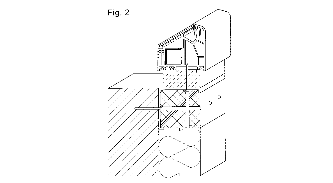
L'invention concerne un profilé pour un système de fixation et d'isolation thermique de fenêtres, portes et façades; un élément essentiel de celui-ci étant un fer d'angle (1), en un matériau quelconque, de préférence en acier, dont la section transversale ressemble à la lettre " L ", qui comporte des points d'inflexion longitudinaux (2) disposés le long des bords de ses deux bras, qui sont courbés vers l'intérieur du fer d'angle (1), de préférence à un angle de 90 °. Le fer d'angle (1) "L" est rempli d'un composé de remplissage (3). En outre, grâce au laminage des bords du fer d'angle (1) et à la présence de points d'inflexion longitudinaux (2) du fer d'angle (1) formé de cette manière, il est possible de placer l'entretoise (4) entre eux, laquelle dilate les bras du fer d'angle (1). L'entretoise (4) peut être sensiblement la barre plate longitudinale, et elle peut présenter des trous ou des saillies; éventuellement, l'entretoise (4) peut être constituée de petits panneaux disposés respectivement le long de la longueur du fer d'angle (1) "L". L'entretoise susmentionnée (4) forme toujours un angle aigu, avec le bras du fer d'angle (1) auquel elle est adjacente, et avec des points d'inflexion longitudinaux (2) sortant de ce bras, lequel angle est normalement de 45 °. L'entretoise (4) est ensuite la bissectrice de l'angle défini par le bras du fer d'angle (1) et du point d'inflexion longitudinal (2) . Dans la solution basique, le profil est fixé à la face de paroi au moyen d'éléments de fixation, des broches ou des vis (7). La vis (7) passant à travers le bras horizontal du fer d'angle (1) fixe le cadre de la fenêtre, de la porte porte ou d'autres éléments de façade au fer d'angle (1) "L". L'installation peut être également effectuée avec l'utilisation d'ancrages de fixation (6), directement connectés au profil et supportant relativement le profil, puis être également reliée à la paroi du bâtiment. Des ancrages de fixation (6) peuvent comprendre un ou plusieurs pivots (8). Ils peuvent également être constitués de plusieurs éléments coulissants (9), permettant la séparation, et ainsi l'allongement des ancrages de fixation (6). L'utilisation de pivots (8), qui peuvent avoir la forme de charnières, est améliorée par la résistance des ancrages de fixation (6).


Abrégé anglais

The subject of the invention is the profile for the fastening and thermal insulation system of windows, doors and facades, an essential element of which is the angle iron (1), made of any material, preferably of steel, with the cross section resembling the letter "L", which has longitudinal inflection points (2) arranged along the edges of its both arms, which are bent towards the inside of the angle iron (1), preferably at an angle of 90°. The angle iron (1) "L" is filled with the filling compound (3). In addition, thanks to rolling of the edges of the angle iron (1) and the presence of longitudinal inflection points (2) of the iron angle (1) formed this way, it is possible to place the brace (4) between them, which expands the arms of the angle iron (1). The brace (4) may be substantially the longitudinal flat bar, whereby it can have holes or protrusions; optionally the brace (4) can be made of small boards arranged respectively along the length of the angle iron (1) "L". The aforementioned brace (4) always forms an acute angle - with the arm of the angle iron (1), which it is adjacent to and with longitudinal inflection points (2) going out of this arm - which angle is typically 45°. The brace (4) is then the bisector of the angle defined by the arm of the angle iron (1) and of the longitudinal inflection point (2). In the basic solution - the profile is fixed to the wall face by means of fasteners, pins or screws (7). The screw (7) passing through the horizontal arm of the angle iron (1) fixes the frame of the window, door or other facade elements to the angle iron (1) "L". The installation may be also performed with the use of fixing anchors (6), directly connected to the profile, relatively supporting the profile, and then also connected to the building wall. Fixing anchors (6) may be equipped with one or several swivels (8). They may also be made of several sliding elements (9), enabling the separation, and thus the elongation of fixing anchors (6). The use of swivels (8), which may have the form of hinges, is improved by the strength of fixing anchors (6).

Revendications

Note : Les revendications sont présentées dans la langue officielle dans laquelle elles ont été soumises.


claims
1. The profile for the fastening and thermal insulation system of windows,
doors and
facades is characterized in that, its main structural element is the angle
iron (1)
with the cross section resembling the shape of the letter ,,L", made of any
material, with longitudinal inflection points (2), arranged along the edge of
both
arms, which are bent towards the inside of the angle iron (1), preferably at
an
angle of 90°, wherein the angle iron (1) is filled with the filling
compound (3).
2. The profile for the fastening and thermal insulation system of windows,
doors and
facades, according to claim 1, is characterized in that, the angle iron (1) is
made of
steel or steel sheet or other alloy, or of a glass fiber composite or a carbon
fiber
composite.
3. The profile for the fastening and thermal insulation system of windows,
doors and
facades, according to claim 1 or 2, is characterized in that, the filling
compound
(3) is the synthetic foam, or the carbon fiber composite.
4. The profile for the fastening and thermal insulation system of windows,
doors and
facades, according to claim 1, 2 or 3, is characterized in that, between the
rolled
edges of the angle iron (1) in longitudinal inflection points (2) of the angle
iron (1)
is placed the brace, expanding the arms of the angle iron (1).
5. The profile for the fastening and thermal insulation system of windows,
doors and
facades, according to one of the claims 1-4, is characterized in that, the
brace (4)
is substantially the longitudinal flat bar, which preferably has holes or
protrusions,
or the brace (4) is formed by small boards, arranged respectively along the
length
of the angle iron (1).
6. The profile for the fastening and thermal insulation system of windows,
doors and
facades, according to one of the claims 1-5, is characterized in that, the
brace
creates an acute angle - with the arm of the angle iron (1) which it is
adjacent to,
and with longitudinal inflection points (2) going out from this arm - which
angle is
typically 45°.
7. The profile for the fastening and thermal insulation system of windows,
doors and
facades, according to one of the claims 1-6, is characterized in that, the
brace (4)
is the bisector of the angle defined by the arm of the angle iron (1) and the
longitudinal inflection point (2).

8. The profile for the fastening and thermal insulation system of windows,
doors and
facades, according to one of the claims 1-7, is characterized in that, the
profile
with the angle iron (1), longitudinal inflection points (2), filling compound
(3) and
optionally the brace (4) is the structural element with the cross section of
preferably isosceles right triangle.
9. The profile for the fastening and thermal insulation system of windows,
doors and
facades, according to one of the claims 1-8, is characterized in that, it is
filled with
an additional filling compound (3), which gives various shapes to the profile,
which
its different cross sections result from.
10. The profile for the fastening and thermal insulation system of windows,
doors and
facades, according to one of the claims 1-9, is characterized in that, the
developed
profile has holes (5), made in the course of production of the profile or
during its
installation.
11. The profile for the fastening and thermal insulation system of windows,
doors and
facades, according to one of the claims 1-10, is characterized in that, along
its
length are arranged and attached fixing anchors (6).
12. The profile for the fastening and thermal insulation system of windows,
doors and
facades, according to one of the claims 1-11, is characterized in that it is
fixed to
the wall face by fasteners, pins or screws (7).
13. The profile for the fastening and thermal insulation system of windows,
doors and
facades, according to one of the claims 11 or 12, is characterized in that,
fixing
anchors (6) are equipped with one or several swivels (8).
14. The profile for the fastening and thermal insulation system of windows,
doors and
facades, according to one of the claims 11, 12 or 13, is characterized in
that, fixing
anchors (6) are made of several sliding elements (9), allowing the separation
or
the extension of fixing anchors (6).
15. The profile for the fastening and thermal insulation system of windows,
doors and
facades, according to one of the claims 13 or 14, is characterized in that,
swivels
(8) have the form of hinges.

Description

Note : Les descriptions sont présentées dans la langue officielle dans laquelle elles ont été soumises.


CA 03014418 2018-08-13
WO 2017/048144 PCT/PL2016/000104
Profile for the fastening and thermal insulation system of windows, doors and
facades
The subject matter of the invention is the profile for the fastening and
thermal
insulation system of windows, doors and facades, preferably placed in the area
of
insulation of structures, multi-family buildings, single-family buildings, as
well as public
buildings, livestock buildings and farm buildings. The profile is developed
for the
installation of windows, doors and facades, both made of PVC, as well as
aluminum and
timber, irrespective of their dimensions.
There are many solutions for the design of fastening elements of building
facades
to the face of the wall, such as window, door, and others.
From the Polish description of the invention with the application number
P.294954 (publ. BUP No. 26/1993 of 27 December 1993) it is known the solution
entitled
"The method for making contact areas of the window and the wall and the
thermal
insulation element to apply this method". The presented invention solves the
problem of
elimination of thermal bridges at the contact area of the window and the wall.
The
method involves placing the thermal insulation element at the horizontal
contact area of
the window and the wall, which is also the external windowsill. The thermal
insulation
element is made of the thermal insulation material in the form of a narrow
board having
a trapezoidal shape in its cross section. On the surface of the thermal
insulation material
is placed a thin layer of the plastic mass with a grid.
From the next Polish description of the utility model with the application
number
W-101801 (publ. BUP No. 14/1996 of 8 July 1996) it is known the solution
entitled "The
element for embedding aluminum windows with the thermal separator". The
subject of
the presented utility model is the element for embedding aluminum windows with
the
thermal separator, as well as tilt-turn windows in standing construction
containers. The
element for embedding aluminum windows with the thermal separator is the
monolithic
molding made of the wall and the walls with edges juxtaposed at right angles,
wherein
the relationships between the width of the wall to the wall in different sizes
are
expressed by the following ratios: 1.6 to 1.19 to 1 and 2.3 to 1, most
preferably 1.9 to 1.
The wall has mounting through holes, and the window with the element is fixed
to the
window hole by the screw element.
From another Polish description of the utility model with the application
number
W-115579 (publ. BUP No. 02/2007 of 22 January 2007) it is known the solution
entitled
"The angular element of the thermal insulation housing". The presented angular
element
of the thermal insulation housing comprises the base and the side wall made of
the
thermal insulation board, in which between two stiffening linings is placed
the layer of
the thermal insulation material. The base and the side wall are
interconnected, forming

CA 03014418 2018-08-13
WO 2017/048144 PCT/PL2016/000104
the edge of the angular bend at the connection point. The angular element has
on the
one side of the opposite face edges the longitudinal sealing protrusions, and
on the other
side, the longitudinal sealing seat.
From the other Polish description of the utility model with the application
number
W-119897 (pub!. BUP No. 21/2012 of 8 October 2012) it is known the solution
entitled
"The steel profile reinforcing windows and doors with the thermal pad". The
presented
reinforcing steel profile for windows and doors made of PVC profiles,
constituting the
upper and side steel element, separated by the rolled thermal pad, is
characterized in
that the upper element comprises the bend forming the protrusion and the seat
created
between the inflection point of the bend and the single inflection point of
the bend, in
which it has embedded by one end the thermal pad placed by the second end in
the seat
of the side element, formed between the double inflection point of the bend
and the
single inflection point of the bed, wherein the vertical arm of the side
element has a
bent.
The aim of the invention it to develop a profile for the fastening and thermal
insulation system of windows, doors and facades, which will facilitate and
allow the
installation of windows, doors and elements of the facade to the face of the
wall, made
of any material. The invention aims to strengthen the profile itself, making
it possible to
limit the structural elements in the building.
The essence of the profile for the fastening and thermal insulation system of
windows, doors and facades is that its main structural element is the angle
iron with the
cross section reminiscent of the shape of the letter "L", made of any
material, with
longitudinal inflection points made along the edges of both arms, which are
bent
towards the interior of the angle iron, preferably at an angle of 900, wherein
the angle
iron is filled with the filling compound.
Preferably, the angle iron is made of steel or steel sheet or other alloy, or
of the
glass fiber composite or the carbon fiber composite.
Preferably, the filling compound is made of the synthetic foam, or the carbon
fiber
corn posite.
Preferably, between the rolled edges of the angle iron in longitudinal
inflection
points of the angle iron is placed the brace that expands the arms of the
angle iron.
Preferably, the brace is substantially comprised by the longitudinal flat bar,
in
which holes or bumps can be made, or the brace is comprised by small boards
arranged
respectively along the length of the angle iron.
Preferably, the brace forms an acute angle¨with the arm of the angle iron,
which
it adheres to and with longitudinal inflection points going out from this arm
¨ which
angle is typically 450.

CA 03014418 2018-08-13
WO 2017/048144 PCT/PL2016/000104
Preferably, the brace is the bisector of the angle defined by the arm of the
angle
iron and the longitudinal inflection point.
Preferably, the profile with the angle iron, longitudinal inflection points,
filling
compound and optionally the brace is the structural element with the cross
section of an
preferably isosceles right triangle.
Preferably, the profile is supplemented by an additional mass, preferably the
filling
compound, giving various shapes to the profile, which result in its various
sections.
Preferably, the developed profile has holes, made in the course of the
production
of the profile or during its installation.
Preferably, along the length of the profile are arranged and installed fixing
anchors.
Preferably, the profile is fixed to the face of the wall using fasteners, pins
or
screws.
Preferably, fixing anchors are provided with one or more swivels.
Preferably, fixing anchors are made of several sliding elements, allowing the
displacement and extension of fixing anchors.
Preferably, swivels are in the form of hinges.
According to the invention, the solution enables easy and extremely fast, and
at
the same time very solid and stable fixing the various elements of facades,
windows and
doors to the building wall face. In addition, the solution can reduce the
number of
structural elements in the building, because the fixing profile can be a
separate structural
element, which, compared to earlier solutions, carries much greater load
values. This is
possible thanks to a specific stress distribution, acting in the profile,
after suspending on
it the elements of the facade, such as windows or doors. The developed profile
for the
fastening and thermal insulation system of windows, doors and facades allows
you to
achieve maximum strength with a minimal amount of material used for this
profile.
The developed solution facilitates the installation of windows and doors out
of the
hole in the wall, allowing for easier carrying the thermal insulation layer
directly to the
window or door, and consequently eliminating any thermal bridges that can
occur when
connecting to the face of the wall, doors or other facade elements.
The invention is described in the example drawings, in which Fig. 1 ¨ presents
a
schematic cross section through the wall of the building, using the profile
for the
fastening and thermal insulation system of windows, doors and facades, Fig. 2
¨ presents
an axonometric sectional view of a particular form of the profile and the wall
section,
and Fig. 3 ¨ presents another, special form of the profile in an axonometric
view, with
the element ornamenting the facade of the building, Fig. 4 ¨ presents a
schematic cross
section through the wall of the building, using the profile in which fixing
anchors are
additionally used, Fig. 5 ¨ presents an axonometric sectional view of a
particular form of

CA 03014418 2018-08-13
WO 2017/048144 PCT/PL2016/000104
the profile with fixing anchors, Fig. 6, Fig. 7, Fig. 8, Fig. 9, Fig. 10, Fig.
11 and Fig. 12 ¨
present different designs of fixing the profile to the wall, using fixing
anchors equipped
with a various number of differently localized swivels and sliding elements.
As shown in the drawings, an essential structural element of the profile for
the
fastening and thermal insulation system of windows, doors and facades is the
angle iron
1, made of any material, such as sheet (steel or other alloy), glass fiber
composite or
carbon fiber composite, preferably of steel with a cross section resembling
the shape of
the letter "L", whereas the composites will improve the insulation factor of
the profile.
The angle iron 1 "L" has longitudinal inflection points 2, arranged along the
edge of its
both arms, which are bent towards the interior of the angle iron 1, at an
angle of 900.
The angle iron 1 õL" is filled with the filling compound 3, preferably the
synthetic
foam, or the carbon fiber composite. In addition, by rolling the edges of the
angle iron 1
¨ the presence of longitudinal inflection points 2 of the angle iron 1, formed
this way ¨ it
is possible to place the brace 4 between them, expanding the arms of the angle
iron 1.
The filling compound 3 expands and stiffens the arms of the angle iron 1,
thereby
preventing buckling the arms of the angle iron 1.
Thanks to the use of the filling compound 3, the angle iron 1 õL" is not
deformed
under transferred loads, resulting from the suspension of the elements of the
facade of
the building on it. The filling compound 3 is also the thermal insulation
layer and the
sealing layer, protecting against negative atmospheric conditions, such as
wind.
The filling compound 3 carries loads, while the additionally used brace 4
improves
the strength of the profile structure.
The brace 4 may substantially comprise the longitudinal flat bar, whereas it
is
possible to make holes or protrusions in it; possibly, the brace 4 may consist
of small
boards arranged respectively along the length of the angle iron 1 "L".
Possibly made 4
holes and gaps in the brace facilitate the installation of the angle iron 1
"L" and reduce its
weight, while the protrusions made in the brace 4 improve its properties, such
as
strength and stiffness.
The aforementioned brace 4 always creates an acute angle ¨ from the arm of the
angle iron 1 to which it is adjacent, as well as with longitudinal inflection
points 2 going
out of this arm ¨ which angle is typically 45 . The brace 4 constitutes then
the bisector of
the angle, defined by the arm of the angle iron 4 and the longitudinal
inflection point 2.
The profile with such an angle iron 1, longitudinal inflection points 2,
filling
compound 3 and optionally with the brace 4 of the fastening and thermal
insulation
system of windows, doors and facades ¨ is a structural element with the cross
section of
possibly isosceles right triangle, with a very high lifting force.
In the profile without the brace 4, the described loads are carried by the
filling
compound 3, which carries from 500 kg to 1200 kg per 100 cm2. In turn, in the
profile
with the brace 4, loads are carried by the filling compound 3 and the brace 4,
so that we

CA 03014418 2018-08-13
WO 2017/048144 PCT/PL2016/000104
can sum up the aforementioned load strength of the filling compound 3 and in
addition
the compressive strength of the brace 4, which is from 0 to 100 kg per 1
linear meter.
Thus, the strength of the profile for the fastening and thermal insulation
system of
windows, doors and facades reaches up to 2.5 tons per 1 linear meter.
The developed profile may be supplemented by the compound, such as the filling
compound 3, which can be formed in different ways, giving various shapes to
the profile,
which result from its various cross sections. The profile shaped this way may
be at the
same time used as a decorative element of the building facade, as shown in
Figure 3.
The shape of the triangle formed by the angle iron 1, and possibly,
additionally by
the brace 4, which are complemented by the filling compound 3 ¨ is much less
susceptible to deformations of previously known angle irons, than the
structure itself,
The profile is placed on the face of the wall, at a height depending on the
design of
the building and the need to install other elements on it. Fixing the profile
to the wall
face, and installing other elements of the facade, is possible with holes 5,
made earlier in
the course of the production of the profile, or during its installation. The
installation may
be also performed in a different way, with the use of fixing anchors 6,
connected directly
to the profile, optionally supporting the profile, and then connected also to
the building
wall.
in the basic solution ¨ the profile is fixed to the wall face by means of
fasteners,
pins or screws 7. The screw 7, passing through the horizontal arm of the angle
iron 1,
fixes the frame of the window, door or other facade elements to the angle iron
1 "L".
Stresses caused by the pressure of facade elements, doors or windows are
transferred through the horizontal arm in both directions, i.e. from the wall
face and to
the wall face. Horizontal force directed outside the building, is transferred
from the wall
face to the wall face by the hypotenuse of the right triangle. Horizontal
force directed to
the wall is, however, transferred to the wall face by the hypotenuse directed
vertically
downward, as shown in Figure 1.
Fixing anchors 6 may be equipped with one or more swivels 8. They can also be
made of several sliding elements 9, enabling the separation, and thus, the
elongation of
fixing anchors 6.
The use of swivels 8, which may take the form of hinges, improves the strength
of
fixing anchors 6, since the fixing anchor 6 equipped with swivels 8, is
affected only by
shear forces, but not by moments or transverse forces. In this way, the
profile lacks line
stresses, but is only influenced by point stresses. The presence of swivels 8
also
facilitates transport and installation of the profile.
To such a profile for fastening and thermal insulation of windows, doors and
facades the thermal insulation of the building is directly carried and
installed. On the
profile are arranged windows, doors and other facade elements. The profile is

CA 03014418 2018-08-13
WO 2017/048144 PCT/PL2016/000104
additionally sealed with the polyurethane foam or other resilient materials,
which
thermally and acoustically insulate the building and protect it against rain
and win.

CA 03014418 2018-08-13
WO 2017/048144
PCT/PL2016/000104
List of elements:
1. angle iron,
2. longitudinal inflection point,
3. filling compound,
4. brace (expanding),
5. hole (transverse),
6. fixing anchor,
7. screw,
8. swivel,
9. sliding element.

Dessin représentatif
Une figure unique qui représente un dessin illustrant l'invention.
États administratifs

2024-08-01 : Dans le cadre de la transition vers les Brevets de nouvelle génération (BNG), la base de données sur les brevets canadiens (BDBC) contient désormais un Historique d'événement plus détaillé, qui reproduit le Journal des événements de notre nouvelle solution interne.

Veuillez noter que les événements débutant par « Inactive : » se réfèrent à des événements qui ne sont plus utilisés dans notre nouvelle solution interne.

Pour une meilleure compréhension de l'état de la demande ou brevet qui figure sur cette page, la rubrique Mise en garde , et les descriptions de Brevet , Historique d'événement , Taxes périodiques et Historique des paiements devraient être consultées.

Historique d'événement

Description Date
Demande non rétablie avant l'échéance 2022-03-16
Le délai pour l'annulation est expiré 2022-03-16
Réputée abandonnée - omission de répondre à un avis relatif à une requête d'examen 2021-12-07
Lettre envoyée 2021-09-16
Réputée abandonnée - omission de répondre à un avis sur les taxes pour le maintien en état 2021-03-16
Représentant commun nommé 2020-11-07
Lettre envoyée 2020-09-16
Représentant commun nommé 2019-10-30
Inactive : Réponse à l'art.37 Règles - PCT 2018-11-14
Inactive : Page couverture publiée 2018-08-29
Inactive : CIB en 1re position 2018-08-28
Inactive : CIB attribuée 2018-08-28
Inactive : Demande sous art.37 Règles - PCT 2018-08-23
Inactive : Notice - Entrée phase nat. - Pas de RE 2018-08-22
Inactive : CIB attribuée 2018-08-20
Demande reçue - PCT 2018-08-20
Exigences pour l'entrée dans la phase nationale - jugée conforme 2018-08-13
Demande publiée (accessible au public) 2017-03-23

Historique d'abandonnement

Date d'abandonnement Raison Date de rétablissement
2021-12-07
2021-03-16

Taxes périodiques

Le dernier paiement a été reçu le 2019-09-13

Avis : Si le paiement en totalité n'a pas été reçu au plus tard à la date indiquée, une taxe supplémentaire peut être imposée, soit une des taxes suivantes :

  • taxe de rétablissement ;
  • taxe pour paiement en souffrance ; ou
  • taxe additionnelle pour le renversement d'une péremption réputée.

Les taxes sur les brevets sont ajustées au 1er janvier de chaque année. Les montants ci-dessus sont les montants actuels s'ils sont reçus au plus tard le 31 décembre de l'année en cours.
Veuillez vous référer à la page web des taxes sur les brevets de l'OPIC pour voir tous les montants actuels des taxes.

Historique des taxes

Type de taxes Anniversaire Échéance Date payée
Taxe nationale de base - générale 2018-08-13
Rétablissement (phase nationale) 2018-08-13
TM (demande, 2e anniv.) - générale 02 2018-09-17 2018-08-13
TM (demande, 3e anniv.) - générale 03 2019-09-16 2019-09-13
Titulaires au dossier

Les titulaires actuels et antérieures au dossier sont affichés en ordre alphabétique.

Titulaires actuels au dossier
"ERGO PLUS" SP. Z.O.O.
Titulaires antérieures au dossier
ARTUR BORUSZEWSKI
Les propriétaires antérieurs qui ne figurent pas dans la liste des « Propriétaires au dossier » apparaîtront dans d'autres documents au dossier.
Documents

Pour visionner les fichiers sélectionnés, entrer le code reCAPTCHA :


Pour visualiser une image, cliquer sur un lien dans la colonne description du document. Pour télécharger l'image (les images), cliquer l'une ou plusieurs cases à cocher dans la première colonne et ensuite cliquer sur le bouton "Télécharger sélection en format PDF (archive Zip)" ou le bouton "Télécharger sélection (en un fichier PDF fusionné)".

Liste des documents de brevet publiés et non publiés sur la BDBC .

Si vous avez des difficultés à accéder au contenu, veuillez communiquer avec le Centre de services à la clientèle au 1-866-997-1936, ou envoyer un courriel au Centre de service à la clientèle de l'OPIC.


Description du
Document 
Date
(aaaa-mm-jj) 
Nombre de pages   Taille de l'image (Ko) 
Abrégé 2018-08-12 2 87
Dessins 2018-08-12 9 179
Revendications 2018-08-12 2 89
Description 2018-08-12 7 310
Dessin représentatif 2018-08-12 1 24
Rappel de taxe de maintien due 2018-08-20 1 111
Avis d'entree dans la phase nationale 2018-08-21 1 193
Avis du commissaire - non-paiement de la taxe de maintien en état pour une demande de brevet 2020-10-27 1 539
Courtoisie - Lettre d'abandon (taxe de maintien en état) 2021-04-05 1 552
Avis du commissaire - Requête d'examen non faite 2021-10-06 1 532
Avis du commissaire - non-paiement de la taxe de maintien en état pour une demande de brevet 2021-10-27 1 549
Courtoisie - Lettre d'abandon (requête d'examen) 2022-01-03 1 551
Rapport prélim. intl. sur la brevetabilité 2018-08-12 5 200
Traité de coopération en matière de brevets (PCT) 2018-08-12 1 71
Traité de coopération en matière de brevets (PCT) 2018-08-12 1 36
Modification - Abrégé 2018-08-14 1 21
Rapport de recherche internationale 2018-08-12 3 79
Demande d'entrée en phase nationale 2018-08-12 4 113
Déclaration 2018-08-12 1 79
Requête sous l'article 37 2018-08-22 1 55
Réponse à l'article 37 2018-11-13 2 40