Note : Les descriptions sont présentées dans la langue officielle dans laquelle elles ont été soumises.
318665-3
COMPOSITIONS FOR EROSION AND MOLTEN DUST RESISTANT
ENVIRONMENTAL BARRIER COATINGS
FIELD OF TECHNOLOGY
[0001] Embodiments of the present invention generally relate to
environmental barrier
coatings for ceramic components, along with methods of making the same.
BACKGROUND
[0002] Higher operating temperatures for gas turbine engines are
continuously being
sought in order to improve their efficiency. However, as operating
temperatures increase,
the high temperature durability of the components of the engine must
correspondingly
increase. Significant advances in high temperature capabilities have been
achieved through
the formulation of iron, nickel, and cobalt-based superalloys. Still, with
many hot gas path
components constructed from superalloys, thermal barrier coatings (TBCs) can
be utilized
to insulate the components and can sustain an appreciable temperature
difference between
the load-bearing alloys and the coating surface, thus limiting the thermal
exposure of the
structural component.
[0003] While superalloys have found wide use for components used throughout
gas
turbine engines, and especially in the higher temperature sections,
alternative lighter-
weight substrate materials have been proposed, such as ceramic matrix
composite (CMC)
materials. CMC and monolithic ceramic components can be coated with
environmental
barrier coatings (EBCs) to protect them from the harsh environment of high
temperature
engine sections. EBCs can provide a dense, hermetic seal against the corrosive
gases in the
hot combustion environment.
[0004] Silicon carbide and silicon nitride ceramics undergo oxidation in
dry, high
temperature environments. This oxidation produces a passive, silicon oxide
scale on the
surface of the material. In moist, high temperature environments containing
water vapor,
1
CA 3014455 2018-08-16
318665-3
such as a turbine engine, both oxidation and recession occurs due to the
formation of a
passive silicon oxide scale and subsequent conversion of the silicon oxide to
gaseous
silicon hydroxide, which results in dimensional loss of the material. For
component
applications of silicon-based substrates in turbine engines, such material
loss can open up
clearances and may lead to efficiency losses, and ultimately may lead to
perforation of the
component.
[0005] As such, an environmental barrier coating (EBC) is applied onto the
surface of
the ceramics to help protect the underlying component. Current materials
commonly used
for environmental barrier coatings on CMC's include celsian-phase barium
strontium
aluminosilicate (BSAS) and rare earth silicates. All of these materials are
relatively stable
in steam compared to the CMC and can prevent penetration of steam to the CMC
if present
as a dense coating layer.
[0006] However, these materials have varying resistance against molten
environmental
contaminant compositions, particularly those containing oxides of calcium,
magnesium,
aluminum, silicon, and mixtures thereof. Dirt, ash, and dust ingested by gas
turbine
engines, for instance, are often made up of such compounds, which often
combine to form
contaminant compositions comprising mixed calcium-magnesium-aluminum-silicon-
oxide systems (Ca-Mg-Al-Si-0), hereafter referred to as "CMAS." At the high
turbine
operating temperatures, these environmental contaminants can adhere to the hot
barrier
coating surface, and thus cause damage to the EBC. For example, CMAS can form
compositions that are liquid or molten at the operating temperatures of the
turbines. The
molten CMAS composition can dissolve the barrier coating, or can fill its
porous structure
by infiltrating the pores, channels, cracks, or other cavities in the coating.
Upon cooling,
the infiltrated CMAS composition solidifies and reduces the coating strain
tolerance, thus
initiating and propagating cracks that may cause delamination and spalling of
the coating
material.
[0007] In particular, molten dust reacts strongly with BSAS to form a low
temperature
eutectic and phases that are not stable in steam. Molten dust is less
corrosive against rare
2
CA 3014455 2018-08-16
318665-3
earth silicates. Some rare earth silicates (e.g. those comprised of
gadolinium, erbium, and
yttrium) react with the molten dust to form highly refractory "apatite"
phases. Others rare
earth silicates allow CMAS penetration but do not suffer melt point
suppression. All rare
earth silicates, however, are mechanically weakened by their interaction with
molten dust,
such that subsequent erosion and impact events can more easily take off the
coating.
[0008] A need exists, therefore, for coating compositions that are less
susceptible to
molten dust attack, and also less susceptible to subsequent gas erosion,
particle erosion,
and particle impact over the current state-of-the-art EBC materials.
BRIEF DESCRIPTION
[0009] Aspects and advantages will be set forth in part in the following
description, or
may be obvious from the description, or may be learned through practice of the
invention.
[0010] A coating system is generally provided for positioning on a surface
of a
substrate (e.g., a CMC substrate). In on embodiment, the coating system
includes a layer
having a compound of the formula:
A1-bBbZ1-dDaM06
where: A is Al, Ga, In, Sc, Y, Ce, Pr, Nd, Pm, Sm, Eu, Gd, Tb, Dy, Ho, Er, Tm,
Yb, Lu,
Fe, Cr, Co, Mn, Bi, or a mixture thereof; b is 0 to about 0.5; Z is Hf, Ti, or
a mixture thereof;
D is Zr, Ce, Ge, Si, or a mixture thereof; d is 0 to about 0.5; and M is Ta,
Nb, or a mixture
thereof.
[0011] A coated component is also generally provided, which may include a
ceramic
substrate (e.g., a CMC substrate) having a surface; and a coating system on
the surface of
the ceramic substrate, wherein the coating system comprises a layer including
a compound
having the formula:
At-bBbZi-dDaM06
3
CA 3014455 2018-08-16
318665-3
where: A is Al, Ga, In, Sc, Y, Ce, Pr, Nd, Pm, Sm, Eu, Gd, Tb, Dy, Ho, Er, Tm,
Yb, Lu,
Fe, Cr, Co, Mn, Bi, or a mixture thereof; b is 0 to about 0.5; Z is Hf, Ti, or
a mixture thereof;
D is Zr, Ce, Ge, Si, or a mixture thereof; d is 0 to about 0.5; and M is Ta,
Nb, or a mixture
thereof.
[0012] Methods are also generally provided for forming a coating on a
surface of a
substrate. In one embodiment, the method may include applying a slurry onto
the surface
of the substrate, with the slurry comprising a compound dispersed within a
solvent and
having the formula:
A1_bBbZ1-aDdM06
where: A is Al, Ga, In, Sc, Y, Ce, Pr, Nd, Pm, Sm, Eu, Gd, Tb, Dy, Ho, Er, Tm,
Yb, Lu,
Fe, Cr, Co, Mn, Bi, or a mixture thereof; b is 0 to about 0.5; Z is Hf, Ti, or
a mixture thereof;
D is Zr, Ce, Ge, Si, or a mixture thereof; d is 0 to about 0.5; and M is Ta,
Nb, or a mixture
thereof.
[0013] These and other features, aspects and advantages will become better
understood
with reference to the following description and appended claims. The
accompanying
drawings, which are incorporated in and constitute a part of this
specification, illustrate
embodiments of the invention and, together with the description, serve to
explain certain
principles of the invention.
BRIEF DESCRIPTION OF THE DRAWINGS
[0014] A full and enabling disclosure of the present invention, including
the best mode
thereof, directed to one of ordinary skill in the art, is set forth in the
specification, which
makes reference to the appended Figs., in which:
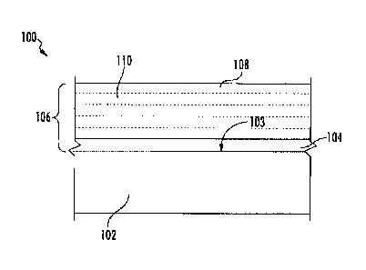
[0015] FIG. 1 shows an exemplary coated component having a substrate with a
coating
system thereon;
4
CA 3014455 2018-08-16
318665-3
[0016] FIG. 2 shows an exemplary coated component having a substrate with a
coating
system thereon; and
[0017] FIG. 3 is a schematic cross-sectional view of a gas turbine engine
which may
include the coated component of FIG. 1 therein.
[0018] Repeat use of reference characters in the present specification and
drawings is
intended to represent the same or analogous features or elements of the
present invention.
DETAILED DESCRIPTION OF PARTICULAR EMBODIMENTS
[0019] Reference now will be made in detail to embodiments of the
invention, one or
more examples of which are illustrated in the drawings. Each example is
provided by way
of explanation of the invention, not limitation of the invention. In fact, it
will be apparent
to those skilled in the art that various modifications and variations can be
made in the
present invention without departing from the scope of the invention. For
instance, features
illustrated or described as part of one embodiment can be used with another
embodiment
to yield a still further embodiment. Thus, it is intended that the present
invention covers
such modifications and variations as come within the scope of the appended
claims and
their equivalents.
[0020] In the present disclosure, when a layer is being described as "on"
or "over"
another layer or substrate, it is to be understood that the layers can either
be directly
contacting each other or have another layer or feature between the layers,
unless expressly
stated to the contrary. Thus, these terms are simply describing the relative
position of the
layers to each other and do not necessarily mean "on top of' since the
relative position
above or below depends upon the orientation of the device to the viewer.
[0021] Chemical elements are discussed in the present disclosure using
their common
chemical abbreviation, such as commonly found on a periodic table of elements.
For
example, hydrogen is represented by its common chemical abbreviation H; helium
is
represented by its common chemical abbreviation He; and so forth. As used
herein, "Ln"
CA 3014455 2018-08-16
318665-3
refers to a rare earth element or a mixture of rare earth elements. More
specifically, the
"Ln" refers to the rare earth elements of scandium (Sc), yttrium (Y),
lanthanum (La),
cerium (Ce), praseodymium (Pr), neodymium (Nd), promethium (Pm), samarium
(Sm),
europium (Eu), gadolinium (Gd), terbium (Tb), dysprosium (Dy), holmium (Ho),
erbium
(Er), thulium (Tm), ytterbium (Yb), lutetium (Lu), or mixtures thereof.
[0022] Compositions are generally provided for use as part of an
environmental barrier
coating (EBC), along with methods of coating a component with such
compositions.
Additionally, coating systems are generally provided for use as an EBC coated
on a surface
of a substrate, along with their methods of formation and the resulting coated
components.
[0023] Generally, the compositions described herein are less susceptible to
molten
dust, erosion, impact, and/or mixed mode degradation mechanisms than current
EBC
compositions. Thus, the compositions provided herein may result in a more
robust EBC,
compared to current-state-of-the-art EBC, that remains on the substrate
material to protect
it from recession against water vapor in turbine engine environments. In
summary, these
materials exhibit better resistance against molten dust as compared to BSAS
and rare earth
silicate EBC materials, and may have higher hardness than BSAS and rare earth
silicate
materials, particular after exposure to molten dust (e.g., CMAS). Thus, the
compound add
resistance to particle erosion and impact to a coating formed from such
materials (e.g., an
EBC).
[0024] Referring now to the drawings, FIG. 1 shows an exemplary coated
component
100 with a substrate 102 having a coating system 106 thereon. Generally, the
coating
system 106 includes an optional bond coating 104 on the surface 103 of the
substrate and
an EBC 108 on the optional bond coating 104. In the embodiment shown, the bond
coating
104 is directly on the surface 103 without any layer therebetween. However, in
other
embodiments, one or more layers can be positioned between the bond coating
104, when
present, and the surface 103. In other embodiments, the EBC 108 may be formed
directly
on the surface 103 of the substrate 102.
6
CA 3014455 2018-08-16
6
318665-3
[0025] The EBC 108 may include any combination of one or more
layers 110 formed
from materials selected from typical EBC or thermal barrier coating ("TBC")
layer
chemistries, including but not limited to rare earth silicates (e.g., mono-
silicates and di-
silicates), aluminosilicates (e.g., mullite, barium strontium aluminosilicate
(BSAS), rare
earth aluminosilicates, etc.), hafnia, zirconia, stabilized hafnia, stabilized
zirconia, rare
earth hafnates, rare earth zirconates, rare earth gallium oxide, etc.
[0026] In accordance with one particular embodiment, at least
one of the layers 110 of
the EBC 108 includes a compound having the formula:
A1-bBbl1-ciDdM06 (Formula 1)
where A is Al, Ga, In, Sc, Y, Ce, Pr, Nd, Pm, Sm, Eu, Gd, Tb, Dy, Ho, Er, Tm,
Yb, Lu, Fe,
Cr, Co, Mn, Bi, or a mixture thereof; b is 0 to about 0.5 (e.g., 0 to about
0.2, such as greater
than 0 to about 0.5 or about 0.001 to about 0.2); Z is Hf, Ti, or a mixture
thereof; D is Zr,
Ce, Ge, Si, or a mixture thereof; d is 0 to about 0.5 (e.g., 0 to about 0.2,
such as about 0.001
to about 0.5 or about 0.001 to about 0.2); and M is Ta, Nb, or a mixture
thereof.
Compounds of Formula 1 may exhibit properties that are similar or better than
existing
BSAS and rare earth silicate materials in terms of stability in high
temperature steam.
Additionally, these materials may exhibit better resistance against molten
dust as compared
to BSAS and rare earth silicate EBC materials. Furthermore, these materials
may have
higher hardness than BSAS and rare earth silicate materials, particularly
after exposure to
molten dust. This results in the coating being more resistant to particle
erosion and impact.
[0027] Generally, the compound having the Formula 1 may have
multiple phases in
the layer 110, such as an orthorhomibic phase (e.g., with Pbcn or Pnma space
groups), a
tetragonal phase (e.g., with P42/mnm), or a monoclinic phase (e.g., with
P2/c). As such,
these materials may have a structure that is completely different (in terms of
phase) than
TBC layers formed from material containing hafnium oxides or zirconium oxides,
which
typically have the phase P21/c for monoclinic hafnia and monoclinic zirconia,
or the phase
P42/nmc for tetragonal hafnia and zirconia, or the cubic structure for hafnia
and zirconia.
7
CA 3014455 2018-08-16
ii
318665-3
[0028] It is to be understood that the compound has distinct "sites" in its
composition,
with the "A site" being formed by A and/or B of Formula 1, the "Z site" being
formed by
Z and/or D of Formula 1, the "M site," and the oxygens.
[0029] In certain embodiment, the compound may include a single element in
the "A
site" such that b is 0 and A is an element selected from the group consisting
of Al, Ga, In,
Sc, Y, Ce, Pr, Nd, Pm, Sm, Eu, Gd, Tb, Dy, Ho, Er, Tm, Yb, Lu, Fe, Cr, Co, Mn,
and Bi.
In one exemplary embodiment, when b is 0 and A is Al, the compound is:
AlZ1_dDdM06
(e.g., A1ZM06 when d is 0, such as AlHfTa06). In another exemplary embodiment,
when
b is 0 and A is Y, the compound has the formula: YZi_dDdM06 (e.g., YZMO6 when
d is 0,
such as YHfTa06). In still another exemplary embodiment, when b is 0 and A is
Er, the
compound has the formula: ErZ1_dDaM06 (e.g., ErZMO6 when d is 0, such as
ErffiTa06).
[0030] The "A site" of the compound having Formula 1 includes, in one
particular
embodiment, aluminum (Al) in combination with another A element (e.g., Ga, In,
Sc, Y,
Ce, Pr, Nd, Pm, Sm, Eu, Gd, Tb, Dy, Ho, Er, Tm, Yb, Lu, Fe, Cr, Co, Mn, Bi, or
a mixture
thereof). Without wishing to be bound by any particular theory, it is believed
that the
presence of Al in the compound increases the hardness of the coating. In
certain
embodiments, Al is present in combination with another element at the "A site"
and then
the compound can be described as having the formula:
AkA16136Z1-aDdM06 (Formula 2)
where x is about 0.01 to about 0.99; A is Ga, In, Sc, Y, Ce, Pr, Nd, Pm, Sm,
Eu, Gd, Tb,
Dy, Ho, Er, Tm, Yb, Lu, Fe, Cr, Co, Mn, Bi, or a mixture thereof; b is 0 to
about 0.5 (e.g.,
0 to about 0.2, such as about 0.001 to about 0.5 or about 0.001 to about 0.2);
Z is Hf, Ti, or
a mixture thereof; D is Zr, Ce, Ge, Si, or a mixture thereof; d is 0 to about
0.5 (e.g., 0 to
about 0.2, such as about 0.001 to about 0.5 or about 0.001 to about 0.2); and
M is Ta, Nb,
or a mixture thereof. In certain embodiments, x is about 0.05 to about 0.9,
such as about
0.1 to about 0.75. In one particular embodiment, up to half of the element
mixture at the
8
CA 3014455 2018-08-16
318665-3
A site of the compound of Formula 1 may be Al (e.g., x is about 0.1 to about
0.5 in the
compound of Formula 2).
[0031] In addition to Al, the "A site" of the compound having Formula 1
includes, in
one particular embodiment, a combination of Al and gallium (Ga), with or
without the
presence of another A element (e.g., In, Sc, Y, Ce, Pr, Nd, Pm, Sm, Eu, Gd,
Tb, Dy, Ho,
Er, Tm, Yb, Lu, Fe, Cr, Co, Mn, Bi, or a mixture thereof). Without wishing to
be bound
by any particular theory, it is believed that the presence of Ga in the
compound reduces the
average ionic radius of at the A site, which adjusts the coefficient of
thermal expansion
(CTE) of the layer 110. Thus, the amount of Ga in the compound may be used to
control
the CTE of the layer 110 to adjust it to be as close to the CTE of the
adjacent layers within
the coating system 106 and/or the CTE of the substrate 102.
[0032] When the compound includes Al and Ga in a portion of the "A site,"
then the
compound can be descried as having the formula:
AlxGayA1-x_y_bBbZ1_aDdM06 (Formula 3)
where x is about 0.01 to about 0.99 as described above with respect to Formula
2; y is about
0.01 to about 0.9; x + y is 1 or less; A is In, Sc, Y, Ce, Pr, Nd, Pm, Sm, Eu,
Gd, Tb, Dy,
Ho, Er, Tm, Yb, Lu, Fe, Cr, Co, Mn, Bi, or a mixture thereof; b is 0 to about
0.5 (e.g., 0 to
about 0.2, such as about 0.001 to about 0.5 or about 0.001 to about 0.2); Z is
Hf, Ti, or a
mixture thereof; D is Zr, Ce, Ge, Si, or a mixture thereof; d is 0 to about
0.5 (e.g., 0 to about
0.2, such as about 0.001 to about 0.5 or about 0.001 to about 0.2); and M is
Ta, Nb, or a
mixture thereof. Another element may be present at the A site in the compound
of Formula
3 when x + y is less than 1 (i.e., x + y> 1). In one particular embodiment, up
to half of the
element mixture at the A site of the compound of Formula 1 may be Al (e.g., x
is about 0.1
to about 0.5 in the compound of Formula 3) and up to half of the element
mixture at the A
site of the compound of Formula 1 may be Ga (e.g., y is about 0.1 to about 0.5
in the
compound of Formula 3).
9
CA 3014455 2018-08-16
h
318665-3
[0033] In particular embodiments, erbium (Er), yttrium (Y),
and/or holmium (Ho) may
be included within the A site of the compounds having the Formula 1, Formula
2, and/or
Formula 3 (i.e., A includes Er, Y, Ho, or a mixture thereof in any of Formulas
1, 2, or 3).
Without wishing to be bound by any particular theory, it is believed that the
Er, Y, and/or
Ho may provide CMAS resistance to the layer 110 formed from such a compound.
[0034] Referring to Formulas 1-3 where b is greater than 0,
boron (B) dopes the "A
site" of the compound of Formula 1 to change the CTE and/or the sintering
temperature of
the layer formed from the compound. Additionally, B may migrate to other
layers (e.g.,
the bond coating and/or thermally growth oxide layer) to help those layers
interact with
CMAS and/or to control the crystalition of those layers. However, in other
embodiments,
b is 0 such that no B is present in the compound.
[0035] The "Z site" of any of the compounds having Formula 1,
2, or 3 may be utilized,
in one particular embodiment, to help control the CTE of the compound.
Generally, the
CTE of the compound is directly proportional to the ionic radius of at Z site.
For example,
the CTE of the compound decreases as the ionic radius of the Z site element
decreases. In
particular embodiments, the Z site may include Hf, Ti, or a mixture thereof,
such as
represented in Formula 4:
A1_bBbHfhTitD1-h-tM06 (Formula 4)
where h is 0 to 1, t is 0 to 1, and h + t is greater than 0 to 1; A is Al, Ga,
In, Sc, Y, Ce, Pr,
Nd, Pm, Sm, Eu, Gd, Tb, Dy, Ho, Er, Tm, Yb, Lu, Fe, Cr, Co, Mn, Bi, or a
mixture thereof;
b is 0 to about 0.5 (e.g., 0 to about 0.2, such as about 0.001 to about 0.5 or
about 0.001 to
about 0.2); D is Zr, Ce, Ge, Si, or a mixture thereof; and M is Ta, Nb, or a
mixture thereof.
In one particular embodiment of Formula 4, the A site may include Al (e.g., as
discussed
above with respect to Formula 2), Ga (e.g., as discussed above with respect to
Formula 3),
and/or other materials, and/or 8 (e.g., as discussed above with respect to
Formulas 1, 2, or
3). In certain embodiments, h + t may be greater than 0 but less than 1, such
that another
element (D) is present at the Z site.
CA 3014455 2018-08-16
1,
318665-3
[0036] In one embodiment, Hf is present in the compound such that h is
greater than 0
to 1 (e.g., about 0.05 to about 1). In one particular embodiment when both Hf
and Ti are
present in the compound (i.e., both h and t are greater than 0), Hf may be
present in a molar
amount that is greater than the amount of Ti, such that h is greater than t.
In one
embodiment, Hf may be the majority of the element in terms of molar ration
(i.e., h is 0.5
to 1) at the Z site. For example, h may be 1 in particular embodiments, such
that t is 0 and
1-t is 0 (i.e., Hf is the sole element at the Z site). Without wishing to be
bound by any
particular theory, it is believed that Hf in the Z site may increase hardness
and the steam
resistance of the coating formed from such a compound.
[0037] In particular embodiments, where Hf is present in the "Z site"
(i.e., Z includes
Hf either alone or in combination with Ti and/or D), a combination of elements
may be
included in the "A site." For example, such a compound may have the formula:
AxBbLn i-x-bHfl-t-dTitDdM0 6 (Formula 5)
where: A is Al, Ga, In, Sc, Y, Ce, Pr, Nd, Pm, Sm, Eu, Gd, Tb, Dy, Ho, Er, Tm,
Yb, Lu,
Fe, Cr, Co, Mn, Bi, or a mixture thereof; x is about 0.01 to about 0.99; b is
0 to about 0.5
with 1-x-b being 0 to about 0.99 such that Ln is present in the compound; Ln
is Sc, Y, La,
Ce, Pr, Nd, Pm, Sm, Eu, Gd, Tb, Dy, Ho, Er, Tm, ytterbium Yb, Lu, or a mixture
thereof,
and with Ln being different than A in terms of composition; t is 0 to about
0.99; D is Zr,
Ce, Ge, Si, or a mixture thereof; d is 0 to about 0.5; the sum of t and d is
less than 1 such
that Hf is present in the compound; and M is Ta, Nb, or a mixture thereof.
[0038] When A includes Al in combination with another element, Formula 5
can be
modified as follows:
AlxA'aBbLni-x-a-bHfi-t-dTitDdM06 (Formula 6)
where: x is about 0.01 to about 0.99 such that Al is present in the compound;
A' is Ga, In,
Sc, Y, Ce, Pr, Nd, Pm, Sm, Eu, Gd, Tb, Dy, Ho, Er, Tm, Yb, Lu, Fe, Cr, Co, Mn,
Bi, or a
mixture thereof; a is 0 to about 0.99; b is 0 to about 0.5, with 1-x-a-b being
0 to about 0.99
11
CA 3014455 2018-08-16
318665-3
such that Ln is present in the compound; Ln is Sc, Y, La, Ce, Pr, Nd, Pm, Sm,
Eu, Gd, Tb,
Dy, Ho, Er, Tm, ytterbium Yb, Lu, or a mixture thereof, and wherein Ln is
different than
A in terms of composition; t is 0 to about 0.99; D is Zr, Ce, Ge, Si, or a
mixture thereof; d
is 0 to about 0.5; the sum of t and d is less than 1 such that Hf is present
in the compound;
and M is Ta, Nb, or a mixture thereof.
[0039] For
example, both Al and Ga may be present at the A site in combination with
another element (with Hf included in the Z site), such as in the formula:
Al,GayBbLn1_x_y_bHf1-t-ciTitDdM06 (Formula 7)
where: x is about 0.01 to about 0.99 such that Al is present in the compound;
y is about
0.01 to about 0.99 such that Ga is present in the compound; b is 0 to about
0.5, with 1-x-a-
b being 0 to about 0.99 such that Ln is present in the compound; Ln is Sc, Y,
La, Ce, Pr,
Nd, Pm, Sm, Eu, Gd, Tb, Dy, Ho, Er, Tm, ytterbium Yb, Lu, or a mixture
thereof, and
wherein Ln is different than A in terms of composition; t is 0 to about 0.99;
D is Zr, Ce,
Ge, Si, or a mixture thereof; d is 0 to about 0.5; the sum of t and d is less
than 1 such that
Hf is present in the compound; and M is Ta, Nb, or a mixture thereof.
[0040] The
material of the "M site" of the compound of any of Formulas 1-7 may
influence the phase allowance and CTE of the resulting compound. In one
particular
embodiment, the M site may be Nb without any additional element present, which
may
provide better phase allowance and CTE matching when utilized as a layer
within an EBC
coating.
[0041] As
stated, the compound of any of Formulas 1-7 may be included in a layer of
an EBC 108 of the coating system 106 so as to provide a material having
minimal reaction
with CMAS and has high hardness (e.g., for erosion resistance) after reaction
with CMAS.
Thus, the material of the compounds of any of Formulas 1-7 may be included
within a layer
of the EBC with other materials of an EBC layer, or may be used to form a
separate layer
within the EBC 108. In one embodiment, a layer of the EBC 108 is formed from
the
12
CA 3014455 2018-08-16
318665-3
compound of any of Formulas 1-7, and may have a thickness of about 1 gm to
about 1 mm
(e.g., 1 gm to about 100 gm).
[0042] In one embodiment, the compound of any of Formulas 1-7 may be
included in
an outermost layer of an EBC 108 of the coating system 106, such that the
compound may
help protect the underlying EBC layers and substrate 102. The substrate 102
may be
formed from a ceramic matrix composite ("CMC") material, such as a silicon
based, non-
oxide ceramic matrix composite. As used herein, "CMC" refers to a silicon-
containing, or
oxide-oxide, matrix and reinforcing material. As used herein, "monolithic
ceramics" refers
to materials without fiber reinforcement (e.g., having the matrix material
only). Herein,
CMCs and monolithic ceramics are collectively referred to as "ceramics."
[0043] Some examples of CMCs acceptable for use herein can include, but are
not
limited to, materials having a matrix and reinforcing fibers comprising non-
oxide silicon-
based materials such as silicon carbide, silicon nitride, silicon oxycarbides,
silicon
oxynitrides, and mixtures thereof. Examples include, but are not limited to,
CMCs with
silicon carbide matrix and silicon carbide fiber; silicon nitride matrix and
silicon carbide
fiber; and silicon carbide/silicon nitride matrix mixture and silicon carbide
fiber.
Furthermore, CMCs can have a matrix and reinforcing fibers comprised of oxide
ceramics.
Specifically, the oxide-oxide CMCs may be comprised of a matrix and
reinforcing fibers
comprising oxide-based materials such as aluminum oxide (Al2O3), silicon
dioxide (SiO2),
aluminosilicates, and mixtures thereof. Aluminosilicates can include
crystalline materials
such as mullite (3A1203 2Si02), as well as glassy aluminosilicates.
[0044] Particularly suitable compounds for use as a relatively thick or
thin EBC layer
may have a particularly close coefficient of thermal expansion (CTE) to the
underlying
CMC substrate. For example, aluminum containing hafnium tantalates may be
particularly
suitable compounds having CTEs relatively close to that of the CMC substrate.
For
example, aluminum containing hafnium tantalates may have the formula:
Ali _x_yA 'xA"yHfra.06 (Formula 8)
13
CA 3014455 2018-08-16
318665-3
where A' is Er, Sm, or a mixture thereof; x is about 0.3 to about 0.45; A" is
In, Ga, or a
mixture thereof; y is about 0.15 to about 0.35; and (x + y) is about 0.5 to
about 0.7 such
that Al is present from about 0.3 to about 0.5. In particular embodiments, A'
is either Er
or Sm, and/or A" is either In or Ga. The compound of Formula 8 may also be
referring to
from Formula 1 where (referring to Formula 1) A includes Al in combination
with two
other elements (A' and A" of Formula 8); b is 0, Z is Hf, d is 0, and M is Ta.
[0045] Particularly suitable compounds for use as a relatively thin EBC
layer (e.g.
having a thickness of about 100 gm or less) may have a coefficient of thermal
expansion
(CTE) that is close to the CTE of the underlying CMC substrate but not within
a CTE
matching relations. For example, erbium containing hafnium tantalates may be
particularly
suitable compounds for such EBC layers, and may have the formula:
Al1_x-yEr,GayHfTa06 (Formula 9)
where x is about 0.4 to about 0.6; y is 0 to about 0.4; and (x + y) is about
0.5 to about 0.85
such that Al is present from about 0.15 to about 0.5. The compound of Formula
9 may also
be referring to from Formula 1 where (referring to Formula 1) A includes a
combination of
Er, Al, and Ga; b is 0, Z is Hf, d is 0, and M is Ta.
[0046] As shown, the bond coating 104 is optionally positioned on the
surface 103 of
the substrate 102 between the substrate 102 and the EBC 108. When present, the
bond
coating 104 includes silicon or a silicon based material (e.g., a silicide,
etc.). Generally,
the bond coating 104 is relatively thin, such as having a thickness that is
about 25
micrometers (gm) to about 275 gm, such as about 25 gm to about 150 gm (e.g.,
about 25
gm to about 100).
[0047] FIG. 2 shows a thermally grown oxide ("TGO") layer 105, which may
form on
the surface of the silicon-based bond coating 104, such as a layer of silicon
oxide
(sometimes referred to as "silicon oxide scale" or "silica scale"), during
exposure to oxygen
(e.g., during manufacturing and/or use) of the component 100.
14
CA 3014455 2018-08-16
318665-3
[0048] The coated component 100 of FIG. 1 is particularly suitable for use
as a
component found in high temperature environments, such as those present in gas
turbine
engines, for example, combustor components, turbine blades, shrouds, nozzles,
heat
shields, and vanes. In particular, the turbine component can be a CMC
component
positioned within a hot gas flow path of the gas turbine such that the coating
system 106
forms an environmental barrier for the underlying substrate 102 to protect the
component
100 within the gas turbine when exposed to the hot gas flow path.
[0049] FIG. 3 is a schematic cross-sectional view of a gas turbine engine
in accordance
with an exemplary embodiment of the present disclosure. More particularly, for
the
embodiment of FIG. 3, the gas turbine engine is a high-bypass turbofan jet
engine 10,
referred to herein as "turbofan engine 10." As shown in FIG. 3, the turbofan
engine 10
defines an axial direction A (extending parallel to a longitudinal centerline
12 provided for
reference) and a radial direction R. In general, the turbofan 10 includes a
fan section 14
and a core turbine engine 16 disposed downstream from the fan section 14.
Although
described below with reference to a turbofan engine 10, the present disclosure
is applicable
to turbomachinery in general, including turbojet, turboprop and turboshaft gas
turbine
engines, including industrial and marine gas turbine engines and auxiliary
power units.
[0050] The exemplary core turbine engine 16 depicted generally includes a
substantially tubular outer casing 18 that defines an annular inlet 20. The
outer casing 18
encases, in serial flow relationship, a compressor section including a booster
or low
pressure (LP) compressor 22 and a high pressure (HP) compressor 24; a
combustion section
26; a turbine section including a high pressure (HP) turbine 28 and a low
pressure (LP)
turbine 30; and a jet exhaust nozzle section 32. A high pressure (HP) shaft or
spool 34
drivingly connects the HP turbine 28 to the HP compressor 24. A low pressure
(LP) shaft
or spool 36 drivingly connects the LP turbine 30 to the LP compressor 22.
[0051] For the embodiment depicted, the fan section 14 includes a variable
pitch fan
38 having a plurality of fan blades 40 coupled to a disk 42 in a spaced apart
manner. As
depicted, the fan blades 40 extend outwardly from disk 42 generally along the
radial
CA 3014455 2018-08-16
318665-3
direction R. Each fan blade 40 is rotatable relative to the disk 42 about a
pitch axis P by
virtue of the fan blades 40 being operatively coupled to a suitable actuation
member 44
configured to collectively vary the pitch of the fan blades 40 in unison. The
fan blades 40,
disk 42, and actuation member 44 are together rotatable about the longitudinal
axis 12 by
LP shaft 36 across an optional power gear box 46. The power gear box 46
includes a
plurality of gears for stepping down the rotational speed of the LP shaft 36
to a more
efficient rotational fan speed.
[0052] Referring still to the exemplary embodiment of FIG. 3, the disk 42
is covered
by rotatable front nacelle 48 aerodynamically contoured to promote an airflow
through the
plurality of fan blades 40. Additionally, the exemplary fan section 14
includes an annular
fan casing or outer nacelle 50 that circumferentially surrounds the fan 38
and/or at least a
portion of the core turbine engine 16. It should be appreciated that the
nacelle 50 may be
configured to be supported relative to the core turbine engine 16 by a
plurality of
circumferentially-spaced outlet guide vanes 52. Moreover, a downstream section
54 of the
nacelle 50 may extend over an outer portion of the core turbine engine 16 so
as to define a
bypass airflow passage 56 therebetween.
[0053] During operation of the turbofan engine 10, a volume of air 58
enters the
turbofan 10 through an associated inlet 60 of the nacelle 50 and/or fan
section 14. As the
volume of air 58 passes across the fan blades 40, a first portion of the air
58 as indicated
by arrows 62 is directed or routed into the bypass airflow passage 56 and a
second portion
of the air 58 as indicated by arrow 64 is directed or routed into the LP
compressor 22. The
ratio between the first portion of air 62 and the second portion of air 64 is
commonly known
as a bypass ratio. The pressure of the second portion of air 64 is then
increased as it is
routed through the high pressure (HP) compressor 24 and into the combustion
section 26,
where it is mixed with fuel and burned to provide combustion gases 66.
[0054] The combustion gases 66 are routed through the HP turbine 28 where a
portion
of thermal and/or kinetic energy from the combustion gases 66 is extracted via
sequential
stages of HP turbine stator vanes 68 that are coupled to the outer casing 18
and HP turbine
16
CA 3014455 2018-08-16
318665-3
rotor blades 70 that are coupled to the HP shaft or spool 34, thus causing the
HP shaft or
spool 34 to rotate, thereby supporting operation of the HP compressor 24. The
combustion
gases 66 are then routed through the LP turbine 30 where a second portion of
thermal and
kinetic energy is extracted from the combustion gases 66 via sequential stages
of LP turbine
stator vanes 72 that are coupled to the outer casing 18 and LP turbine rotor
blades 74 that
are coupled to the LP shaft or spool 36, thus causing the LP shaft or spool 36
to rotate,
thereby supporting operation of the LP compressor 22 and/or rotation of the
fan 38.
[0055] The combustion gases 66 are subsequently routed through the jet
exhaust nozzle
section 32 of the core turbine engine 16 to provide propulsive thrust.
Simultaneously, the
pressure of the first portion of air 62 is substantially increased as the
first portion of air 62
is routed through the bypass airflow passage 56 before it is exhausted from a
fan nozzle
exhaust section 76 of the turbofan 10, also providing propulsive thrust. The
HP turbine 28,
the LP turbine 30, and the jet exhaust nozzle section 32 at least partially
define a hot gas
path 78 for routing the combustion gases 66 through the core turbine engine
16.
EXAMPLE 1
[0056] Aluminum containing hafnium tantalates, according to Formula 8,
where made
according to the formulas shown in Table 1. Each of these aluminum containing
hafnium
tantalate compounds had a CTE that was close to the CTE of a CMC substrate,
making
these compounds particularly suitable for use as a layer of a EBC coating
system.
Table 1
Compound CTE (x10-6/ F)
Ero.33A10.371n0.3Hrfa06 2.70
SM0.43A10.4Ga0.17Hfra06 1.98
Smo.29Alo.421n0.29Hfl'a06 1.81
SM0.36M0.471n0.171{fra06 2.15
17
CA 3014455 2018-08-16
318665-3
EXAMPLE 2
[0057] Aluminum containing hafnium tantalates, according to Formula 9,
where made
according to the formulas shown in Table 2. Each of these aluminum containing
hafnium
tantalate compounds had a CTE that, while not being particularly close to the
CTE of a
CMC substrate, was still suitable for use as a thin layer of a EBC coating
system.
Table 2
Compound CTE (x10-6/ F)
Ero.48A1o2Gao.32Hfra06 3.88
Er0.557A10.443HM06 3.60
[0058] While there have been described herein what are considered to be
preferred and
exemplary embodiments of the present invention, other modifications of these
embodiments falling within the scope of the invention described herein shall
be apparent
to those skilled in the art.
18
CA 3014455 2018-08-16