Note : Les descriptions sont présentées dans la langue officielle dans laquelle elles ont été soumises.
CA 03014483 2018-08-14
WO 2017/144273 PCT/EP2017/052723
- 1 -
Low-pressure ultraviolet radiator with multiple filaments
The present invention relates to a low-pressure mercury gas discharge lamp of
the type used for disinfection purposes with ultraviolet radiation, and to a
method of operating such lamps.
Low-pressure mercury gas discharge lamps are widely used in the field of
lighting, but also in the field of disinfection because of their pre-dominant
output of ultraviolet radiation, which has a germicidal effect. In
disinfection
applications, the terms "UV lamp" and "UV radiator" are used as equivalents
for high-output low-pressure mercury gas discharge lamps. These terms will
be used in the present specification as well.
While in lighting applications, the main requirements are a balanced spectrum
in the visible wavelength range, a high efficiency of the light output in
relation
to the electric power consumption and a long service life, the requirements of
ultraviolet (UV) radiators are different. The ultraviolet output has to be
very
high because the intensity of the ultraviolet radiation is directly correlated
with
the disinfection efficiency, which means that fewer UV radiators with a higher
UV output can be used for disinfecting water, and that directly reduces the
investment necessary for drinking water or wastewater disinfection
installations. Another important requirement of UV radiators for disinfection
purposes in larger installations is the total power consumption. In drinking
water and wastewater applications, the volume of water per time unit, (i.e.
cubic meters per second) can vary significantly. In order not to waste
unnecessary amounts of ultraviolet radiation and the electric energy
associated with its production, several techniques have been developed to
adapt the output of UV plants to the water flow. There are solutions in which
CA 03014483 2018-08-14
WO 2017/144273 PCT/EP2017/052723
- 2 -
the water is treated in several parallel channels, each being equipped with a
number of UV radiators, and in which individual channels can be closed when
the water flow is low. Other applications provide for the possibility to
reduce
the electric power input of the lamps and consequently dim the lamps to a
lower UV output when the water flow is low. Dimming UV lamps of the low
pressure mercury type is limited to about 30% of the nominal power output
because the filaments at the ends of the lamp are heated by electric discharge
in the lamp, and if the electric power supplied to the discharge is reduced,
the
temperatures of the filaments are also reduced. At a certain point, the
filaments get too cold to provide the necessary electron emission. There is
the
risk that the lamp ceases to function, but also the risk that the filament is
damaged when it is operated at too low temperatures. Therefore, there is a
lower limit for the electric input of UV lamps.
For lighting purposes, there are several prior art documents known which use
more than one filament at each end of the lamp. Such prior art documents are
Chinese patent application CN 1812677 A and Chinese patent
CN 101644389 B, and US patent US 6,756,745 B1. These lamps are used for
lighting purposes and suggest multiple filaments, which are redundant in the
sense that, if one filament is defective, the other filament can be switched
on.
There is no disclosure that the filaments can be of different size and mass.
As
discussed above, the technical challenges in lighting applications are
different
from those in ultraviolet disinfection applications.
It is therefore an object of the present invention to provide a UV low-
pressure
mercury gas discharge lamp which has the capability of being safely operated
at low power levels, i.e. below 30% of the nominal power output and
especially down to about 10% of the nominal power output. It is another
object of the present invention to provide a method for operating UV low-
pressure mercury gas discharge lamps at different power levels, especially in
which power levels are varied at least by a factor of 4, and preferably up to
a
factor of 10 between the lowest and the highest power.
- 3 -
The desired effect is achieved in a lamp with the features by providing two
filaments at each end of the discharge length, wherein the filaments can be
individually supplied with electric energy, and wherein the filaments at each
end are of different size and different mass, the difference being more than
the difference stemming from inevitable production inaccuracies. This
construction allows the lamp to be operated in different modes, namely a high
power mode in which the electric energy is supplied to the larger filament,
which also has the higher mass, and in a low power mode in which the smaller
filament, which also has a lower mass, is powered. Especially the object of
the
invention is solved by a low pressure mercury gas discharge ultraviolet lamp
with a tubular elongate body with two opposing ends, a first end and a second
end, which contains a gas filling, and with at least two electric connectors
at
each end, which are electrically connected to at least one filament being
provided at each end, wherein a discharge length is defined between the
filaments, in which at least two filaments are provided at each end of the
discharge length, wherein the filaments can be individually supplied with
electric energy, and wherein the at least two filaments at the first end are
of
different size and different mass, and the at least two filaments at the
second
end are of different size and different mass.
Optionally, the two filaments can be supplied with power simultaneously,
which leads to an even higher electric power input and hence to a higher UV
output. If the smaller and lighter filament is supplied with electric power,
then
the necessary operating temperature of the smaller filament can be reached at
lower electric power input levels because there is only a small surface area
and
consequently a small mass which has to be heated by the energy of the
discharge arc. At a given electric power, the temperature of the smaller
filament is therefore higher than the temperature of a larger filament would
be. Consequently, if a lower limit of the operating temperature exists, as it
does, the lamp can be operated at a low power input level, as low as 10% of
the nominal power input. This low limit has not been achieved so far. The lamp
CA 3014483 2019-07-23
CA 03014483 2018-08-14
WO 2017/144273 PCT/EP2017/052723
- 4 -
can be operated at this power for extended times without damaging the
filament.
Two preferred embodiments will be described with reference to the drawings,
which show:
Figure 1: a low-pressure gas discharge lamp with four filaments which are
individually contacted;
Figure 2: a low-pressure gas discharge lamp with four filaments, in which each
pair of filaments has one common connector;
Figure 3: a view in axial direction of a filament arrangement; and
Figure 4: a view in axial direction of an alternative filament arrangement.
Figure 1 shows a low-pressure mercury gas discharge lamp 1 with a quartz
body 2 of longitudinal, cylindrical shape. Inside the body 2 there is a gas
filling
3 which usually comprises a noble gas and a small amount of mercury. In the
two opposing ends, first end 4 and second end 5, there are filaments a, b, c
and d provided. The filaments are supported inside the lamp body 2 by two
electrical connections each, that is electrical connections al and a2 of
filament
a, connections bl and b2 of filament b, connections cl and c2 of filament c
and connections dl and d2 of filament d. The connections al to d2 are electric
conductors of sufficient temperature resistance to be molten into the quartz
body 2 and of sufficient rigidity to support the filaments a to d under the
mechanical load that can be expected under operation. The filaments may also
be mounted staggered in the lamp.
As figure 1 illustrates, the filaments a and b are filaments of a relatively
short
length. These filaments are covered with known substances to improve
electron emission under elevated temperatures.
Similarly, the filaments c and d are relatively long filaments. They are of
the
same mechanical and physical composition as the filaments a and b, but
significantly longer. Preferably, the filaments a and b on the one hand and c
and d on the other hand are of the same basic wire material, so that the
CA 03014483 2018-08-14
WO 2017/144273 PCT/EP2017/052723
- 5 -
difference in length of the filaments leads to a different mass of the
filaments.
Filaments a and b are lighter than filaments c and d. The filaments can also
be
made from different material.
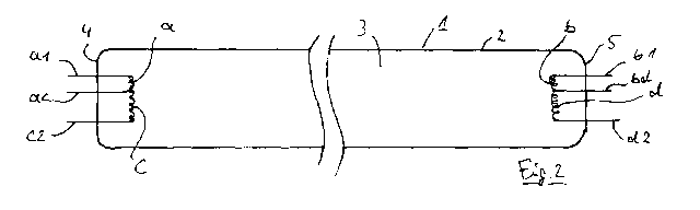
Figure 2 shows an arrangement similar to figure 1. The same numerals are
used for the same or similar components.
In Figure 2, an embodiment uses a pair of small filaments a and b and a
second pair of larger filaments c and d. However, in this embodiment, the
filaments at the end portion 4 of the lamp 1 share a common electric
connection ac. This means that the smaller filament a can be contacted
through two electric connections al and ac, while the second filament c can be
contacted through the connections ac and c2.
The corresponding arrangement on the other end 5 of lamp 1 shows a shorter
filament b with electric connection bl and bd and longer filament d with
electrical connections bd and d2. Accordingly, the filaments b and d share one
common connection bd. Filament b can be contacted electrically via
connections dl and bd, while the filament d can be contacted through the
connections bd and d2.
Figure 3 shows a filament arrangement in a view in axial direction. The lamp
body 2 surrounds a short filament a and a long filament c. The connections at,
a2; cl, c2 are not visible in this view. The arrangement of figure 3 may be
used in embodiments like the one shown in figure 1 in which the filaments a
and c are individually contacted through four independent connectors.
An embodiment with shared connectors is represented in figure 4. In this
embodiment, the lamp body 2 surrounds filaments a and c, which are
physically and electrically connected to each other at one end. This end is
contacted and held by the common connector ac, which is not visible in this
representation, because, like connectors at and c2, they are oriented
vertically with respect to the plane of the drawing.
In operation, the low-pressure mercury gas discharge lamps 1 of figure 1 and
figure 2 are UV radiators of the so-called low-pressure/high output type.
These
CA 03014483 2018-08-14
WO 2017/144273 PCT/EP2017/052723
- 6 -
lamps can be operated at roughly 200 Watts of power input. The exact
number is not relevant in the present context.
The process for powering up the lamp 1 is known from conventional UV
radiators of this type. Firstly, a DC current is supplied to connectors cl and
c2
of filament c and connectors dl and d2 of filament d (in the embodiment of
figure 1). Filaments c and d are heated to an elevated temperature until the
desired temperature for thermal electron emission is reached, which is about
1,000 K. For heating purposes the filaments can also be operated with AC
current. At this point, high voltage is applied to the filaments c and d via
connectors cl and c2 and dl and d2 respectively. The high voltage can also be
supplied only to one connector of each filament c and d. This high voltage
leads to a gas charge in the gas filling 3, and consequently to the production
of ultraviolet radiation. The current through the filaments c and d and
through
the plasma which carries the gas discharge inside the lamp is sufficient to
keep the filaments c and d at the desired temperature level which is necessary
for a long service life of the filaments. Now if for any reason the electric
power
supplied to the lamp shall be reduced, for example because the water flow to
be disinfected is reduced and less UV radiation is necessary, the high voltage
supply can be reduced in a known manner, which results in less energy being
available in the plasma and consequently less temperature being produced in
the filaments c and d. This reduction is technically possible down to about
40% or 30% of the nominal power input of the lamp. At this point, the
filaments c and d get too cold for thermal electron emission and, although the
lamp still works, the filaments are subject to premature wear.
At this point, the smaller filaments a and b can be powered up. Depending on
the construction of the lamp, they are already at an elevated temperature
which is sufficient to support the gas discharge, or they may be pre-heated by
application of direct current to the connectors al, a2 and bl, b2. As soon as
the desired temperature of the filaments a and b is reached, these can be
powered by high voltage as described above, and the high voltage supply to
the filaments c and d can be disconnected. The lamp can be operated at a
reduced power input now. The smaller filaments with lower mass compared
with filaments c and d are then heated by the relatively low electric current
CA 03014483 2018-08-14
WO 2017/144273 PCT/EP2017/052723
- 7 -
which supports the gas discharge. The lower mass, however, leads to a higher
temperature under these operating conditions. Therefore, the filaments a and
b will still reach sufficient operating temperature down to reduced power
levels
of about 30% to 10% of the nominal power input of the lamp. Physically, the
lower mass is equivalent to a lower total heat capacity, and the smaller
surface area leads to reduce energy losses via black body radiation.
Switching from the filaments c and d to filaments a and b therefore allows a
further reduction of the power input of the lamp 1 without decreasing the
service life of the filaments.
Likewise, the lamp in figure 2 can be operated accordingly. The difference of
the embodiment in figure 2 is that the common filament ac and bd can be
used as a ground connector for the DC current while the high voltage is
usually supplied to connectors c2 and d2 under high power load, and to
connectors al and bl under low power.
The filaments of one side, a,c or b,d, may be switched in a pulsed pattern
with
or without overlap. The switching of filaments can take place at the end or
within the end of the UV lamp.
The present invention as described in non-limiting embodiments above can
preferably used in UV disinfection plants for drinking water and wastewater in
which the power output of the UV radiators can be reduced when less water
volume per time unit has to be treated. It is possible to reduce the power of
the UV lamp to low power levels, which could not be achieved so far. This
gives the operators of such UV disinfection plants the chance to achieve
significant savings in operating costs.
Alternative embodiments, which have not been described so far, can comprise
more than two filaments at each end.