Note : Les descriptions sont présentées dans la langue officielle dans laquelle elles ont été soumises.
CA 03015276 2018-08-20
WO 2017/132344
PCT/US2017/015085
ONLINE BATTERY CAPACITY ESTIMATION UTILIZING PASSIVE
BALANCING
Field of the Disclosure
[0001] This disclosure relates to a system, an energy storage device, a
battery module and a
method for determining capacity of the energy storage device. This disclosure
also relates to
systems, methods and programs for controlling power to and from an energy
storage device
based on the determined capacity.
Background
[0002] Energy storage devices including storage devices for vehicles such as
hybrid electric
vehicles have a nominal maximum capacity at installation. The maximum capacity
of the
energy storage device decreases over time. The rate of degradation changes
based on
temperature. Further, the rate of degradation is affected by how power is
controlled to and
from the energy storage device. For example, the more an energy storage device
is drained
below a set value or charged above of set value, the rate of degradation
typically increases
and thus the maximum capacity is reduced. Use of the energy storage device
also affects the
rate of degradation. Energy storage devices that are used more frequently will
typically have
a lower maximum capacity than the energy storage device having the same
nominal
maximum capacity at installation that is used less frequently.
[0003] In a system, such as either a series or parallel hybrid electric
vehicle, knowledge of a
current maximum capacity is needed to control the power to and from the energy
storage
device. Power management is based at least on the current state of charge of
the battery. The
current state of charge is relative to the current maximum capacity.
Summary
[0004] Disclosed is a method comprising enabling balancing of current in a
plurality of cells
of a battery module by controlling a switch within each cell. Each cell
includes a balance
resistor. For each cell, the method further comprises storing a voltage of the
respective cell at
a predetermined time after the balancing is enabled. The voltage is sensed
using a precision
voltage sensor in each cell. For each cell, the method further comprises
determining a cell
current, for a predetermined period of time beginning at the predetermined
time after the
balancing is enabled, detecting a voltage of the respective cell at the end of
the predetermined
1
CA 03015276 2018-08-20
WO 2017/132344
PCT/US2017/015085
period of time, determining a change in a state of charge of the respective
cell based on a
change in the voltage over the predetermined period of time and a slope of an
open circuit
voltage curve and determining a cell capacity based on the change in the state
of charge and
the determined cell current for the predetermined period of time.
[0005] The method further comprises storing, in the memory of the battery
microprocessor
the determined cell capacity for each cell and transmitting, a module capacity
to a battery
controller for an energy storage device. The lowest determined cell capacity
for the plurality
of cells, is the module capacity for the battery module.
[0006] Also disclosed is a battery module for an energy storage device. The
module
comprises a plurality of cells, balancing circuit and a microprocessor. The
balancing circuitry
is associated with each cell. The balancing circuitry comprises a balance
resistor, a balance
switch and a precision voltage sensor.
[0007] The balance switch is configured to close to enable current balancing
between the
plurality of cells and open to disable the current balancing. The balance
switch is connected
in series with the balance resistor. The precision voltage sensor is
configured to detect a
voltage of the cell.
[0008] The microprocessor includes a memory. The memory has open circuit
voltage curve
stored therein. The open circuit voltage curve indicates a relationship
between a voltage of a
respective cell and a state of charge for the respective cell.
[0009] The microprocessor configured to receive a signal instructing current
balancing for
the plurality of cells from a battery microprocessor for the energy storage
device, control the
balance switch associated with each cell to close to enable current balancing,
and store in the
memory, a first voltage of each of the plurality of cells. The first voltage
is detected by a
respective precision voltage sensor at a predetermined time after the
balancing is enabled.
The microprocessor is further configured to determine, for each cell of the
plurality of cells, a
cell current, for a predetermined period of time beginning at the
predetermined time after the
balancing is enabled, and store in the memory, a second voltage of each of the
plurality of
cells. The second voltage is detected by the respective precision voltage
sensor at the end of
the predetermined period of time. The microprocessor is further configured to
determine, for
each cell of the plurality of cells, a change in a state of charge of the
respective cell based on
a slope of the open voltage curve stored in memory and a change in the voltage
over the
predetermined period of time determined from the stored first voltage and the
second voltage,
determine, for each cell of the plurality of cells, a cell capacity based on
the change in the
2
CA 03015276 2018-08-20
WO 2017/132344
PCT/US2017/015085
state of charge and the determined cell current for the predetermined period
of time, store, in
the memory, the determined cell capacity for each cell and transmit, a module
capacity to the
battery microprocessor. The lowest determined cell capacity for the plurality
of cells, is the
module capacity for the battery module.
[0010] Also disclosed is an energy storage device. The energy storage device
comprises a
switch, a battery current sensor, a battery microprocessor and a plurality of
battery modules.
[0011] The switch is configured to either electrically isolate the energy
storage device from a
powertrain of a vehicle or electrically couple the energy storage device to
the powertrain.
[0012] The battery current sensor is configured to detect current in the
energy storage device.
[0013] The battery microprocessor is configured to control the switch to open
to electrically
isolate or close to electrically couple based on a signal received from a
system controller.
When the battery microprocessor receives a signal from the system controller
that the vehicle
is off, the battery microprocessor controls the switch to open. The battery
microprocessor
monitors the current detected by the battery current sensor.
[0014] Each of the plurality of modules comprises a plurality of cells. Each
cell is associated
with balancing circuitry. The balancing circuitry comprises a balance
resistor, a balance
switch; and a precision voltage sensor.
[0015] The balance switch is configured to close to enable current balancing
between the
plurality of cells and open to disable the current balancing. The balance
switch is connected
in series with the balance resistor. The precision voltage sensor is
configured to detect a
voltage of the cell.
[0016] Each of the plurality of battery modules further comprises a
microprocessor including
a memory. The memory has an open circuit voltage curve stored therein. The
open circuit
voltage curve indicates a relationship between a voltage of a respective cell
and state of
charge for the respective cell. The plurality of battery modules are coupled
to the battery
microprocessor. After the battery microprocessor determines that the current
of the energy
storage device is zero, the battery microprocessor issues an instruction to
the microprocessor
in each of the plurality of modules to enable current balancing.
[0017] The microprocessor in each of the plurality of modules is configured to
receive the
instruction from the battery microprocessor to enable current balancing for
the plurality of
cells, control the balance switch associated with each cell to close to enable
current balancing
and store in the memory, a first voltage of each of the plurality of cells.
The first voltage is
detected by a respective precision voltage sensor at a predetermined time
after the balancing
3
CA 03015276 2018-08-20
WO 2017/132344
PCT/US2017/015085
is enabled. The microprocessor in each of the plurality of modules is
configured to determine,
for each cell of the plurality of cells, a cell current, for a predetermined
period of time
beginning at the predetermined time after the balancing is enabled and store
in the memory, a
second voltage of each of the plurality of cells. The second voltage is
detected by the
respective precision voltage sensor at the end of the predetermined period of
time. The
microprocessor in each of the plurality of modules is configured to determine,
for each cell of
the plurality of cells, a change in a state of charge of the respective cell
based on a slope of
the open voltage curve stored in memory and a change in the voltage over the
predetermined
period of time determined from the stored first voltage and the second
voltage, determine, for
each cell of the plurality of cells, a cell capacity based on the change in
the state of charge
and the determined cell current for the predetermined period of time and
store, in the memory
the determined cell capacity for each cell. The microprocessor in each of the
plurality of
modules is configured to transmit, a module capacity to the battery
microprocessor. The
lowest determined cell capacity for the plurality of cells, is the module
capacity for the
battery module.
[0018] The battery microprocessor is further configured to store each of the
transmitted
module capacities in a memory of the battery microprocessor and determine a
capacity for the
energy storage device. The capacity for the energy storage device is the
lowest determined
module capacity for the plurality of modules. The battery microprocessor is
further
configured to transmit the determined battery capacity to the system
controller.
[0019] Also disclosed is a power management system for a vehicle comprising a
system
controller configured to control power to and from an energy storage device.
The system
controller is coupled to the energy storage device.
[0020] The energy storage device comprises a switch, a battery current sensor,
a battery
microprocessor and a plurality of battery modules.
[0021] The switch is configured to either electrically isolate the energy
storage device from a
powertrain of a vehicle or electrically couple the energy storage device to
the powertrain.
[0022] The battery current sensor is configured to detect current in the
energy storage device.
[0023] The battery microprocessor is configured to control the switch to open
to electrically
isolate or close to electrically couple based on a signal received from a
system controller.
[0024] When the vehicle is turned off, the system controller is configured to
issue a signal to
the battery microprocessor and when the battery microprocessor receives the
signal from the
system controller that the vehicle is off, the battery microprocessor controls
the switch to
4
CA 03015276 2018-08-20
WO 2017/132344
PCT/US2017/015085
open, and the battery microprocessor monitors the current detected by the
battery current
sensor.
[0025] Each of the plurality of battery modules comprises a plurality of
cells. Each cell is
associated with balancing circuitry. The balancing circuitry comprises a
balance resistor, a
balance switch; and a precision voltage sensor.
[0026] The balance switch is configured to close to enable current balancing
between the
plurality of cells and open to disable the current balancing. The balance
switch is connected
in series with the balance resistor. The precision voltage sensor is
configured to detect a
voltage of the cell.
[0027] Each of the plurality of battery modules further comprises a
microprocessor including
a memory. The memory has an open circuit voltage curve stored therein. The
open circuit
voltage curve indicates a relationship between a voltage of a respective cell
and state of
charge for the respective cell. The plurality of battery modules are coupled
to the battery
microprocessor. After the battery microprocessor determines that the current
of the energy
storage device is zero, the battery microprocessor issues an instruction to
the microprocessor
in each of the plurality of modules to enable current balancing.
[0028] The microprocessor in each of the plurality of modules is configured to
receive the
instruction from the battery microprocessor to enable current balancing for
the plurality of
cells, control the balance switch associated with each cell to close to enable
current balancing
and store in the memory, a first voltage of each of the plurality of cells.
The first voltage is
detected by a respective precision voltage sensor at a predetermined time
after the balancing
is enabled. The microprocessor in each of the plurality of modules is
configured to determine,
for each cell of the plurality of cells, a cell current, for a predetermined
period of time
beginning at the predetermined time after the balancing is enabled and store
in the memory, a
second voltage of each of the plurality of cells. The second voltage is
detected by the
respective precision voltage sensor at the end of the predetermined period of
time. The
microprocessor in each of the plurality of modules is configured to determine,
for each cell of
the plurality of cells, a change in a state of charge of the respective cell
based on a slope of
the open voltage curve stored in memory and a change in the voltage over the
predetermined
period of time determined from the stored first voltage and the second
voltage, determine, for
each cell of the plurality of cells, a cell capacity based on the change in
the state of charge
and the determined cell current for the predetermined period of time and
store, in the memory
the determined cell capacity for each cell. The microprocessor in each of the
plurality of
CA 03015276 2018-08-20
WO 2017/132344
PCT/US2017/015085
modules is configured to transmit, a module capacity to the battery
microprocessor. The
lowest determined cell capacity for the plurality of cells, is the module
capacity for the
battery module.
[0029] The battery microprocessor is further configured to store each of the
transmitted
module capacities in a memory of the battery microprocessor, determine a
capacity for the
energy storage device and transmit the determined battery capacity to the
system controller.
The capacity for the energy storage device is the lowest determined module
capacity for the
plurality of modules.
[0030] The system controller is further configured to store the determined
battery capacity
received from the battery microprocessor. When the vehicle is turned on
subsequently, the
system controller is further configured to control power to and from the
energy storage device
using the determined battery capacity as a maximum capacity for the energy
storage device to
maintain the energy storage device within a predetermined range of the maximum
capacity.
Brief Description of the Drawings
[0031] Figure 1 illustrates an energy storage device in accordance with
aspects of the
disclosure;
[0032] Figure 2 illustrates a battery module with balancing circuitry in
accordance with
aspects of the disclosure;
[0033] Figures 3 and 4 illustrate a method for determining a capacity of an
energy storage
device in accordance with aspects of the disclosure;
[0034] Figure 5 illustrates an example of a open circuit voltage curve storage
stored in a
memory of a Microprocessor in accordance with aspects of the disclosure;
[0035] Figure 6 illustrates a block diagram of a parallel hybrid electric
vehicle in accordance
with aspects of the disclosure;
[0036] Figure 7 illustrates a block diagram of a series hybrid electric
vehicle in accordance
with aspects of the disclosure; and
[0037] Figure 8 illustrates a method for controlling power to and from an
energy storage
devices using the determined capacity in accordance with aspects of the
disclosure.
6
CA 03015276 2018-08-20
WO 2017/132344
PCT/US2017/015085
Detailed Description
[0038] Definitions and Notations
Voc, (t) Open Circuit Cell Voltage of Cell number i at time t
Q Charge of cell i
I cell z Current in cell i
SoC, State of Charge of cell i
C, Amp Hour Capacity of cell i
Vocõ, Module open circuit voltage
/cpu Current drawn from module to power Microprocessor
P Power drawn my Microprocessor
cpu
Rbaiance Resistance of Balancers
'balance _i Balancing current of cell i
[0039] In accordance with aspects of the disclosure, each battery module is
capable of
determining a module capacity during the time that current balancing in the
cells of the
module is occurring and report the same to a battery controller 120 for the
Energy Storage
Device 100. In turn, the Battery Controller 120 determines the capacity of the
Energy Storage
Device 100 and reports the same to a System Controller (described later in
Figure 6). The
System Controller subsequently uses the determined capacity of the Energy
Storage Device
100 as the maximum capacity of the Energy Storage Device when controlling the
power to
and from the Energy Storage Device 100.
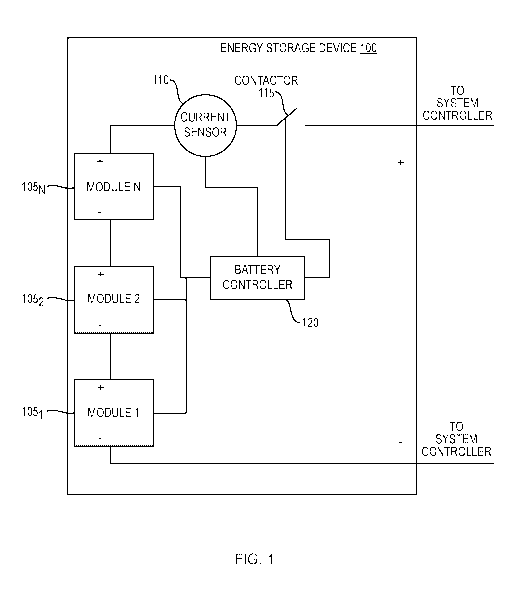
[0040] Figure 1 illustrates a block diagram of an energy storage device 100 in
accordance
with aspects of the disclosure. The Energy Storage Device 100 includes a
Battery Controller
120, a plurality of battery modules (collectively battery modules 105), a
Current Sensor 110
and a Contactor 115. The number of battery modules 105(n) is based on the
needed
maximum capacity of the Energy Storage Device 100. The battery modules 105 are
connected in series. The Battery Controller 120 is coupled to each of the
battery modules
105. The Battery Controller 120 includes a memory (not shown). The memory
stores a
history of the capacities for each module, capacity for the Energy Storage
Device and the
state of health for each module. In another aspect of the disclosure, the
memory can also store
the state of health for Energy Storage Device. The Battery Controller 120 is
coupled to the
System Controller and can receive control information from the System
Controller and report
7
CA 03015276 2018-08-20
WO 2017/132344
PCT/US2017/015085
the capacity for the Energy Storage Device. In another aspect of the
disclosure, the Battery
Controller 120 can also report the state of health for the Energy Storage
Device to the System
Controller.
[0041] The Battery Controller 120 is also coupled to a Current Sensor 110. The
Current
Sensor 110 is configured to detect current through the Energy Storage Device
100. The
Current Sensor 110 is placed in series with the plurality of battery modules
105. The Current
Sensor 110 reports the detected current to the Battery Controller 120.
[0042] The Energy Storage Device 100 also includes a Contactor 115. The
Contactor 115 is
configured to open to isolate the Energy Storage Device 110 from the
powertrain or close to
couple the Energy Storage Device 110 to the powertrain. The Battery Controller
120 controls
the state of the Contactor 115 based on information received from the System
Controller. The
Contactor 115 can be a Single Pole Single Throw Relay. In another aspect of
the disclosure a
semiconductor switch can be used, such as a MOSFET.
[0043] Figure 2 illustrates a battery module with balancing circuitry in
accordance with
aspects of the disclosure. Each module 105 includes a Microprocessor 200
(refer to as
Microprocessor 200 or Microprocessor 200). The Microprocessor 200 includes a
memory
(not shown). The memory stores an open circuit voltage curve indicating a
relationship
between a voltage of a respective cell and a state of charge for the
respective cell and sensed
voltages for each of the cells (and associated time). The memory can also
store the
determined cell capacity for each of a plurality of cells.
[0044] Each module 105 includes a plurality of cells (2151-215N). The cells
2151-215N are
associated with respective balancing circuitry including a high precision
voltage sensor
(2201-220N). The high precision voltage sensor is coupled to the respective
terminals of the
cell (+ terminal and ¨ terminal). For example, a high precision voltage sensor
220i is coupled
to the positive and negative terminal of the cell 1 2151 The precision of the
voltage sensor
impacts the determined capacity. Therefore, the high precision voltage sensor
220 is
configured to detect a voltage of a cell to within a threshold tolerance. For
example, the
accuracy of the high precision voltage sensor is within a voltage threshold of
+- . lmV.
[0045] Each high precision voltage sensor (2201-220N) is coupled to the
Microprocessor 200.
Each high precision voltage sensor (2201-220N) reports the sensed voltage to
the
Microprocessor 200.
[0046] The balancing circuitry includes a Balance Resistor (2101-210N). The
Balance
Resistor 210 is connected in parallel with the cell 215.
8
CA 03015276 2018-08-20
WO 2017/132344
PCT/US2017/015085
[0047] The balancing circuitry further includes a Switch (e.g., 2051-205N). A
switch 205 is
connected in series with the Balance Resistor 210. As depicted in Fig. 2, the
Switch 205 is a
MOSFET. However, other switching devices can be used such as a relay. The
control
terminal of the Switch is connected to the Microprocessor 200. For example, as
depicted in
Fig. 2, the gate of the MOSFET is connected to the Microprocessor 200.
[0048] The Microprocessor 200 controls the Switch 205 to open or close using a
control
signal input to the control terminal. The Switch 210 is used to enable or
disable current
balancing in the cell 215. When current balancing is required, the
Microprocessor 200
controls the Switches (2051-205N) to enable current to pass through a
respective Balance
Resistor (2101-210N), e.g., Switch 205 is closed. The Balance current is
identified as Balance
Current 1-N in Fig. 2.
[0049] When the Switch 205 is opened, current balancing is disabled because of
the open
circuit; current cannot flow through the respective Balance Resistor (2101-
210N).
[0050] The cells 215 are connected in series. The current in each cell flows
from the negative
terminal to the positive terminal during balancing. The cell current is
identified as Cell 1
Current ¨Cell N Current using arrows pointing upward. The Switch 205, Balance
Resistor
210 and high precision voltage sensor 220 is collectively referred to as the
balancing
circuitry.
[0051] The module 105 also includes a Module Positive Terminal 230 and a
Module
Negative Terminal 235. Current flows from the Module Negative Terminal 235 to
the
Module Positive Terminal 230.
[0052] The module 105 also includes a DC/DC converter 225 coupled to the
Microprocessor
200 and the Module Positive Terminal 230 and the Module Negative Terminal 235.
The
DC/DC converter 225 receives as input, the series connection of all of the
cells in the module
105. The DC/DC converter 225 outputs one or more low voltage regulated
sources. The
output(s) of the DC/DC converter 225 are used to power the Microprocessor 200,
memory,
high precision voltage sensors 220 and other balance control circuitry.
[0053] Figures 3 and 4 illustrate a method for determining a capacity of an
energy storage
device in accordance with aspects of the disclosure. Figures 3 and 4 also
illustrate the
interaction between the System Controller 600, the Battery Controller 120 and
the
Microprocessor 200.
[0054] Current balancing and the determination of the capacity of the Energy
Storage Device
occurs when the vehicle is shut down. At S300, the System Controller 600
determines if the
9
CA 03015276 2018-08-20
WO 2017/132344
PCT/US2017/015085
vehicle has been shut down, e.g., off. For example, the System Controller 600
can determine
that the vehicle is off when it receives a key-off signal. If the System
Controller 600 detects
that the vehicle is off ("Y" at S300), the System Controller 600 issues an
instruction to the
Battery Controller 120 to open the Contactor 115, e.g., isolate the Energy
Storage Device 100
from the powertrain.
[0055] At S310, the Battery Controller 120 determines if an instruction is
received from the
System Controller 600. If the Battery Controller 120 receives the instruction
from the System
Controller 600 indicative of the vehicle being off, the Battery Controller 120
controls the
Contactor 115 to open, thereby isolating the Energy Storage Device 100 from
the powertrain
(S310). The Contactor 115 changes from a closed state to an opened state. The
Battery
Controller 120 monitors the current sensed by the Current Sensor 110. The
Battery Controller
120 waits for the sensed current to equal zero to enable current balancing for
the cells. At
S315, the Battery Controller 120 determines if the sensed current is zero. If,
the Battery
Controller 120 determines that the sensed current is zero ("Y" at S315), the
Battery
Controller 120 issues an instruction to the Microprocessor 200 for each module
105 to enable
current balancing (S320). Alternatively, if the Battery Controller 120
determines that the
current is not zero ("N" at S315), the Battery Controller 120 continues to
wait.
[0056] S325-385 is performed by the Microprocessor 200 in each module 105. For
purposes
of the description, the steps will be described with respect to a single
module. However, each
module performs the steps approximately simultaneously.
[0057] At S315, the Microprocessor 200 determines if a balancing instruction
is received
from the Battery Controller 120. If, the Microprocessor 200 receives the
balancing instruction
from the Battery Controller 120 ("Y" at S325), the Microprocessor 200 enables
balancing
within each cell by closing Switches 2051-205N. The Switches change state from
an opened
state to a closed state. Thereby, current can flow across the respective
Balance Resistor 210.
[0058] Batteries, such as Lithium ion batteries have an open circuit charge
and discharge
curve that correlates to a polarization of a cell. For example, after
sufficient charge
throughput the Battery will be biased to the charge open circuit voltage curve
and after
sufficient discharge throughput the battery will be biased to the discharge
open circuit voltage
curve. Figure 5 illustrates an example of the charge 505 and discharge curve
510 for a cell.
Curve 500 is a curve fit of the open circuit voltage indicating an average
open circuit voltage
over a typical SOC operating range of the cell.
CA 03015276 2018-08-20
WO 2017/132344
PCT/US2017/015085
[0059] The curves depicted in Figure 5 are generated during manufacturing and
testing of the
Energy Storage Device, modules and cells. For example, the curves can be
generated by
discharging a cell at a constant current constant voltage CC-CV to a minimum
allowed cell
voltage, e.g., SOC=0%. The cell is then charged with the CC-CV profile to a
maximum
allowed cell voltage. During this time, the current is integrated into the
module in order to
record the AHr capacity of the cell. The cell is at SOC=100%. Afterwards, a
fixed number of
AHr is removed to induce a change in SOC. The cell then rests and the open
circuit voltage is
recorded along with a corresponding SOC. The process is repeated until SOC=0%.
The
discharge curve 510 is plotted using the determined values from the testing.
The charged
curve 505 is similarly created by starting a SOC=0% and stepped up to SOC
=100%
[0060] In order to have the open circuit voltage curve biased to discharge,
the
Microprocessor 200, waits a predetermined time before beginning the capacity
determination.
In an aspect of the disclosure, the predetermined time is 30 minutes or more
after the
balancing of a cell is started.
[0061] The capacity is determined based on the total current drawn from each
cell and
corresponding voltage. The total current drawn from a cell includes a current
of the
microprocessor, Icpu.
[0062] In an aspect of the disclosure, the Microprocessor 200 is modeled as a
fixed power
load, Pepu. The module voltage is a sum of the voltages of the cell.
VOC =IVOC (1)
z=1
The current of the microprocessor Icpu is determined by the following
equation:
I =Pcpu(2)
cPu Vocõ,
[0063] At S335, the Microprocessor 200 determines if the predetermined time
after the start
of the balancing has been reached. The Microprocessor 200 includes a clock or
timer (not
shown). If, the Microprocessor 200 determines that the predetermined time is
reached ("Y" at
S335), the Microprocessor 200 monitors the voltage of the cell Voc, sensed by
the High
precision voltage sensors (2201-220N), for each of the cells (2151-215N). The
voltage, for each
cell, is stored in the memory of the Microprocessor 200 with a time.
[0064] At S340, the Microprocessor 200 determines the current for each cell
for a preset
period of time. The current for each cell is determined by the following
equation:
Icell z=Ibalance z+Icpu (3)
11
CA 03015276 2018-08-20
WO 2017/132344 PCT/US2017/015085
The balance current is determined by the following equation.
Voci
I hal = ______________________ (4)
ance z D
llbalance
[0065] The cell voltages Voci and in turn the module voltage Vocm is
continuous monitored
and updated for equations 2-4.
[0066] The determined currents and voltages are stored in memory of the
Microprocessor
200.
[0067] At S350, the Microprocessor 200 integrates the determined current for
the preset
period of time (coulomb counting) using the following equation:
dQI = Icell zdt (5)
dt
[0068] The integration begins when the first cell voltage for each cell is
recorded (T=0). The
integration ends at the end of the preset period of time (T=t).
[0069] At S355, the Microprocessor 200 determines if the end of the preset
period of time
has been reached. If, the Microprocessor 200 determines that the preset period
of time has not
ended ("N" at S355), the Microprocessor 200 continues to integrate the current
for the preset
period of time (returns to S350).
[0070] At S355, if the Microprocessor 200 determines that the preset period of
time has
ended ("Y" at S355), the Microprocessor 200 stops integrating the current and
monitors the
each cell's voltage, which is sensed by the high precision voltage sensors 220
and records
each cell's voltage at the end of the preset period of time (S360).
[0071] At S365, the Microprocessor 200 determines a change of voltage during
the preset
period of time for each cell. The change of voltage during the preset period
of time for each
cell is determined using the following equation.
dVocl(t) =Voci(t)¨Voci(0) , (6).
dt
where Voc4(0) is the voltage at the start of the preset period of time and
Voci(t) is the voltage
at the end of the preset period of time, for each cell.
[0072] At S370, the Microprocessor 200 retrieves the open circuit voltage
curve that is stored
in the memory for the cells. An example, of the open circuit voltage curve is
depicted in
Figure 5.
12
CA 03015276 2018-08-20
WO 2017/132344
PCT/US2017/015085
[0073] Using the retrieved open circuit voltage curve, the Microprocessor 200
determines the
scope of the curve. Curve 500 is generated in advance and fitting the average
open circuit
voltage to y=mx +b. "M" can be stored in memory. Alternatively, discharge open
circuit
voltage curve can be analyzed in advance at discrete SOC point to generate a
table of slopes.
The table of slopes can be used by the Microprocessor 200 to extract the slope
at a given
SOC operating point.
[0074] The slope of the curve represents:
dVoc,
(7).
dSoC,
[0075] At S375, the Microprocessor 200 determines a change in the state of
charge for each
cell. The change of state of charge is based on the slope of the curve and
change in voltage
during the preset period of time. The change in the state of charge for each
cell is determined
using the following equation:
dVoc,
dSoC, dt (8).
dt dVoc,
dSoC,
[0076] The preset period of time needs to be a sufficient time to avoid
dividing by zero. In an
aspect of the disclosure, the preset period of time is determined based on the
slope of the
open circuit voltage curve. The preset period of time is inversely related to
the slope.
[0077] At S380, the Microprocessor 200 determines the capacity of each cell.
The capacity of
each cell is determined based on the integrated current and the change in the
state of charge.
The capacity of each cell is determined using the following equation:
dQ,
C = dt (9).
I dSoC,
dt
[0078] The capacity for each cell is stored in the memory of the
Microprocessor 200. The
Microprocessor 200 also determines the capacity of the module 105. The
capacity of the
module is equal to the capacity of the cell with the lowest determined
capacity. The module
capacity is stored in the memory of the Microprocessor 200.
[0079] At S385, the Microprocessor 200 reports the determined module capacity
to the
Battery Controller. The controllers/microprocessors communicate with each
other via a
Control Area Network (CAN) bus. The CAN bus is a standard vehicle digital
communication
13
CA 03015276 2018-08-20
WO 2017/132344
PCT/US2017/015085
network and will not be described herein. Alternatively, other digital
communication
infrastructure can be used.
[0080] As described above, the Battery Controller 120 receives the module
capacity from
each of the Microprocessors 200 in the plurality of modules (S390). The module
capacity for
each module 105 is stored in the memory of the Battery Controller 120.
[0081] At S395, the Battery Controller 120 determines the capacity of the
Energy Storage
Device 100 from the received module capacities. The capacity of the Energy
Storage Device
is equal to the capacity of the module with the lowest determined capacity.
The capacity of
the Energy Storage Device is stored in the memory of the Battery Controller
120 in
association with a time. In an aspect of the disclosure, the determined
capacity is stored as a
table with the time of determination.
[0082] At S400, the Battery Controller 120 reports the determined capacity for
the Energy
Storage Device 100 to the System Controller 600. The System Controller 600
stores the
capacity of the Energy Storage Device 100 for later use (S415). The System
Controller 600
uses the determined capacity stored to control power to and from the Energy
Storage Device
100 the next time the vehicle is turned on.
[0083] At S405, the Battery Controller 120 determines a state of health for
the Energy
Storage Device. In an aspect of the disclosure, the state of health ("SOH") is
a metric
indicative of the relationship between the determined capacity and the initial
nominal
capacity for the Energy Storage Device.
[0084] For example, the SOH can be determined by the following equation:
SOH= Initial Nominal Capacity- Determined Capacity
Initial Nominal Capacity (10)
[0085] In another aspect of the disclosure, the state of health is a metric
indicative of the
change in the capacity between two successive capacity determinations.
[0086] For example, the SOH can be determined by the following equation:
SOH= Determined Capacity (T2) ¨Determined Capacity (Ti) (11).
[0087] The Battery Controller 120 stores the SOH of the Energy Storage Device
in memory.
In an aspect of the disclosure, the determined SOH is stored as a table with
the time of
determination. In another aspect of the disclosure, the Battery Controller 120
determines the
SOH using both equations 10 and 11 and separately stores the two SOH values.
14
CA 03015276 2018-08-20
WO 2017/132344
PCT/US2017/015085
[0088] In another aspect of the disclosure, the Battery Controller 120 can
compare the
determined capacities for each module with other modules. If the module
capacity for a given
module 105 is significantly below the other modules, the Battery Controller
120 reports to the
System Controller 600 an indication that a module capacity for the module may
be detective
and replaced.
[0089] At S410, the Battery Controller 120 reports the SOH to the System
Controller 600.
[0090] At S420, the System Controller 600 receives the SOH from the Battery
Controller 120
and stores the same in memory.
[0091] When the vehicle is subsequently turn on, the System Controller 600
retrieves the
SOH from memory. The System Controller 600 compares the SOH with a threshold
(S425).
In an aspect of the disclosure, if the SOH of the Energy Storage Device is
less than the
threshold ("Y"), the System Controller 600 generates an alert (S430). The
generated alert can
be displayed on a panel of the vehicle to alert the driver that the Energy
Storage Device 100
requires maintenance or must be replaced. In another aspect of the disclosure,
multiple
thresholds can be used. For example, a first threshold can be used as an early
warning that the
capacity of the Energy Storage Device 100 should be watched. A second
threshold can be
used as a indicated that the capacity of the Energy Storage Device 100 is
below a required
value and the Energy Storage Device 100 should be replaced. The second
threshold is lower
than the first threshold.
[0092] If the SOH of the Energy Storage Device is not less than the threshold
("N"), the
System Controller 600 does not generate the alert (S435).
[0093] In another aspect of the disclosure, if equation 11 is used to
determine the SOH, the
comparison is if the determined SOH is greater than the threshold. If the
determined SOH is
greater than the threshold, than the change in the capacity is large, which
may indicate a
defective circuit. Additionally, it may indicate that the Energy Storage
Device 100 was
overused in the previous drive cycle.
[0094] If at S300, the System Controller 600 does not detect that the vehicle
is off, e.g., the
vehicle is on, the System Controller 600 execute power management and
regulation as will be
described later for both parallel and series hybrid vehicles.
[0095] Figure 6 illustrates a block diagram of a parallel hybrid electric
vehicle in accordance
with aspects of the disclosure. The parallel hybrid electric vehicle includes
an Energy Storage
Device 100 as described above and System Controller 600 as partially described
above. The
System Controller 600 includes a Clutch Control Assembly for controlling a
clutch assembly
CA 03015276 2018-08-20
WO 2017/132344
PCT/US2017/015085
605. The System Controller 600 includes an inverter (not shown). The parallel
hybrid electric
vehicle includes internal combustion engine (Engine) 640 coupled to an
integrated
starter/generator (ISG) 615 by way of a clutch assembly 605. The ISG 615 is
mechanically
coupled to a transmission 615 by torque converter 620.
[0096] The transmission system 625 provides driver-controlled or vehicle
computer-
controlled gear ratio selection from among at least one gear ratio depending
on velocity,
torque and acceleration requirements. The parallel hybrid electric vehicle
also includes user
interfaces such as a brake 630 and a pedal 635. The pedal 635 is used by the
operator to
increase the torque demand and the brake is used by the operator to decrease
the torque
demand.
[0097] The total torque applied to the transmission system can be a
combination of the torque
provided by both the engine 640 and the ISG 615 when the clutch assembly 605
is closed and
the ISG 615 alone when the clutch assembly 605 is open.
[0098] The System Controller 600 controls the parallel hybrid electric
vehicle. The System
Controller 600 determines the torque sharing or apportioning between engine
640 and the
ISG 615, i.e., the amount of torque provided by the engine 640 and the ISG
615. The
determination is based on the required or demanded torque by the operator of
the vehicle and
the state of charge of the Energy Storage Device 100.
[0099] The System Controller 600 determines the state of charge of the Energy
Storage
Device 100. The state of charge of the Energy Storage Device 100 is determined
based on the
current charge level in the Energy Storage Device 100 versus the maximum
capacity of the
Energy Storage Device 100. When determining the SOC of the battery, the System
Controller
600 uses the latest determined capacity as described above as the maximum
capacity of the
Energy Storage Device 100. In another aspect of the disclosure, the Battery
Controller 120
can compute the SOC using the measured values.
16
CA 03015276 2018-08-20
WO 2017/132344 PCT/US2017/015085
[0100] Figure 8 illustrates a method for controlling power to and from an
energy storage device
using the determined capacity in accordance with aspects of the disclosure.
[0101] The following is a description of an example of the power regulation in
a parallel hybrid
electric vehicle in accordance with aspects of the disclosure.
[0102] The System Controller 600 determines if a change in the demanded torque
is requested or
sensed. At S800, the System Controller 600 determines if there is a request
for an increase in the
total torque. For example, the operator commands an increase in torque via the
pedal 635. If, the
System Controller 600 determined there is an request for increase ("Y" at
S800), the System
Controller 600 determines the current charge level of the Energy Storage
Device 100 (S810) and
retrieves the latest determined capacity of the Energy Storage Device (S805).
At S815, the
System Controller 600 calculates a SOC of the Energy Storage device using
determined capacity
as the maximum capacity of the Energy Storage Device 100 (S815). The SOC is
determined
using the following equation:
SOC= Current Charge/Determined Capacity (12).
[0103] At S820, the power from the Energy Storage Device 100 is controlled
based on the
determined SOC. The System Controller 600 adjusts the torque sharing between
the engine 640
and ISG 615 based on the determined SOC. In an aspect of the disclosure, the
SOC of the Energy
Storage Device is maintained to be between 20%-80% the parallel hybrid
electric vehicle.
Therefore, if the SOC is closer to the lower end of the range, the System
Controller 600 uses less
power from the Energy Storage Device 100. In other words, the System
Controller 600 will
adjust the torque sharing between the between the Engine 640 and ISG 615 to
increase the torque
supplied by the Engine 640 and decrease the torque supplied by the ISG 615.
Additionally, the
System Controller 600 may disengage the clutch to isolate the Engine 640 from
the transmission
system.
[0104] If the SOC is closer to the upper end of the range, the System
Controller 600 uses more
power from the Energy Storage Device 100. In other words, the System
Controller 600 will
adjust the torque sharing between the between the Engine 640 and ISG 615 to
decrease the
torque supplied by the Engine 640 and increase the torque supplied by the ISG
615.
[0105] At S825, the System Controller 600 determines if there is a request for
a decrease in the
total torque or senses deceleration. For example, the operator commands a
decrease in torque via
17
CA 03015276 2018-08-20
WO 2017/132344 PCT/US2017/015085
the brake 630. Additionally, when the vehicle is coasting, the System
Controller 600 determines
that there is a request for a decrease in the total torque.
[0106] If the System Controller 600 determines that there is a request for
decrease in the torque
("Y" at S825), the System Controller 600 retrieves the latest determined
capacity of the Energy
Storage Device (S805). The System Controller 600 determines the current charge
level of the
Energy Storage Device 100. (S810) At S815, the System Controller 600
calculates a SOC of the
Energy Storage device using determined capacity as the maximum capacity of the
Energy
Storage Device 100 using equation 12.
[0107] The System Controller 600 determines whether to allow the ISG 615 to
charge the
Energy Storage Device 100 using regenerative energy. At S830, the System
Controller
determined if the calculated SOC (using the determined capacity as the maximum
capacity) is
greater than a preset maximum. As noted above, for the parallel hybrid
electric vehicle, the SOC
is maintained between 20%-80%. Therefore, the preset maximum can be set to
80%.
[0108] To prevent overcharging, when the SOC is above the preset maximum ("Y"
at S835),
regenerative charging (regenerative braking) of the Energy Storage Device 100
is prevented
(S835). In an aspect of the invention, regenerative charging is prevented by
removing a negative
torque command from the ISG 615. In another aspect of the disclosure, the
Engine 640 can be
used as a load. In yet another aspect of the disclosure a combination of both
can be used. For
example, the regenerative torque can be loaded to the Engine 640 until the
Engine 640 reaches a
maximum speed and then use the mechanical braking system to decelerate the
vehicle.
[0109] Additionally, the System Controller may disengage the clutch assembly
to isolate the
Engine 640 from the Transmission System.
[0110] If the SOC is less than the preset maximum, the System Controller 600
determines
whether the SOC is near the upper end of the predetermined range of 20%-80%.
For example, if
the SOC is above 75% (S840), the System Controller 600 deems the SOC to be
near the upper
end of the predetermined range. If the SOC is near the upper end of the range
("Y" at S840), the
System Controller 600 allows regenerative charging of the Energy Storage
Device 100, but
reduces the power flow into the battery. For example, the System Controller
600 can use the
PWM duty cycle to request less power. In an aspect of the disclosure, the
System Controller 600
18
CA 03015276 2018-08-20
WO 2017/132344 PCT/US2017/015085
commands a negative torque from the ISG 615. The ISG 615 operates as an
electric generator in
order to recoup regenerative braking energy for recharging.
[0111] If at S840, the System Controller 600 determines that the SOC is not
near the upper range
("N" at S840), the System Controller 600 allows regenerative charging of the
Energy Storage
Device 100, at full rating. In an aspect of the disclosure, the System
Controller 600 commands a
negative torque from the ISG 615. The ISG 615 operates as an electric
generator in order to
recoup regenerative braking energy for recharging.
[0112] If the torque demand does not change, the torque sharing may also be
adjusted based on
the current SOC, in a similar manner as described above.
[0113] Figure 7 illustrates a block diagram of a series hybrid electric
vehicle in accordance with
aspects of the disclosure. The series hybrid electric vehicle includes an
Energy Storage Device
100 as described above and System Controller 600A as partially described
above. The series
hybrid includes an Internal Combustion Engine 640A (Engine) directly coupled
to the ISG 615A.
The ISG 615A is coupled to the System Controller 600A. The System Controller
600A is
coupled to an AC Traction Motor 700. The AC Traction Motor 700 is coupled to
the
Transmission System 625 via the torque converter 620. The AC Traction Motor
700 and Engine
640A can be separately operated. The Engine 640A is isolated from the
Transmission System
625.
[0114] The Transmission System 625 provides driver-controlled or vehicle
computer-controlled
gear ratio selection from among at least one gear ratio depending on velocity,
torque and
acceleration requirements. The series hybrid electric vehicle also includes
user interfaces such as
a brake 630 and a pedal 635. The pedal 635 is used by the operator to increase
the torque demand
and the brake is used by the operator to decrease the demanded torque.
[0115] When the Engine 640A is on, the Engine 640A supplies power to the ISG
615 to acts a
generator. The energy from the generator is supplied to the AC Traction Motor
700 via the
System Controller 600A.
[0116] Additionally, power from the Energy Storage Device 100 is supplied to
the AC Traction
Motor 700 via the System Controller 600A. The System Controller 600A includes
an inverter
(not shown).
19
CA 03015276 2018-08-20
WO 2017/132344 PCT/US2017/015085
[0117] If needed, power from the ISG 615A, when acting as a generator can be
supplied to the
Energy Storage Device 100 for recharging.
[0118] The following is a description of an example of the power regulation in
a series hybrid
electric vehicle in accordance with aspects of the disclosure with reference
to Figure 8.
[0119] The System Controller 600A determines if a change in the demanded
torque is requested
or sensed. At S800, the System Controller 600A determines if there is a
request for an increase in
the total torque. For example, the operator commands an increase torque via
the pedal 635. If, the
System Controller 600A determined there is an request for increase ("Y" at
S800), the System
Controller 600A determines the current charge level of the Energy Storage
Device (S810) and
retrieves the latest determined capacity of the Energy Storage Device (S805).
At S815, the
System Controller 600A calculates a SOC of the Energy Storage Device using
determined
capacity as the maximum capacity of the Energy Storage Device 100 (S815). The
SOC is
determined using equation 12.
[0120] At S820, the power from the Energy Storage Device 100 is controlled
based on the
determined SOC. In as aspect of the disclosure, the SOC of the Energy Storage
Device is
maintained between 20%-60% for a series hybrid electric vehicle.
[0121] If the SOC is closer to the lower end of the range, the System
Controller 600A uses less
power from the Energy Storage Device 100. In other words, the System
Controller 600A instruct
the Engine 640A to input to the ISG 615A. The ISG 615A will act as a
generator, e.g., the
System Controller 600A will command a positive torque and the power will be
supplied to the
AC Traction Motor 700 via the System Controller 600A. The generated power by
the ISG 615A
will also be supplied to the Energy Storage Device 100 for recharging via the
System Controller
600A (and its inverter).
[0122] If the SOC is closer to the upper end of the range, the System
Controller 600A uses more
power from the Energy Storage Device 100. In other words, the System
Controller 600A
instructs the Engine 640A to idle. A positive torque command to the ISG 615A
is stopped. Power
from the Energy Storage Device 100 is supplied to the AC Traction Motor 700
via the System
Controller 600A.
[0123] At S825, the System Controller 600A determines if there is a request
for a decrease in the
total torque or senses deceleration. For example, the operator commands a
decrease in torque via
CA 03015276 2018-08-20
WO 2017/132344 PCT/US2017/015085
the brake 630. Additionally, when the vehicle is coasting, the System
Controller 600A
determines that there is a request for a decrease in the total torque.
[0124] The System Controller 600A determined there is a request for decrease
in torque ("Y" at
S825), the System Controller 600A retrieves the latest determined capacity of
the Energy Storage
Device (S805). The System Controller 600A determines the current charge level
of the Energy
Storage Device. (S810) At S815, the System Controller 600A calculates a SOC of
the Energy
Storage device using determined capacity as the maximum capacity of the Energy
Storage
Device 100 using equation 12.
[0125] The System Controller 600A determines whether to allow the AC Traction
Motor 700 to
charge the Energy Storage Device 100. At S830, the System Controller
determines if the
calculated SOC (using the determined capacity as the maximum capacity) is
greater than a preset
maximum. As noted above, for the series hybrid electric vehiclee the SOC is
maintained between
20%-60%. Therefore, the preset maximum can be set to 60%.
[0126] To prevent overcharging, when the SOC is above the preset maximum ("Y"
at S835), the
Energy Storage Device 100 is not charge (S835). If the Engine 640A is on or
the ISG 615A is
commanded for a torque, the System Controller 600A issues commands reducing
the torque from
the ISG 615A and/or output from the Engine 640A. For example, depending on the
torque
needed, the Engine 640A may idle.
[0127] If the SOC is less than the preset maximum, the System Controller 600A
determines
whether the SOC is near the upper end of the predetermined range of 20%-60%.
For example, if
the SOC is above 55% (S840), the System Controller 600A deems the SOC to be
near the upper
end of the predetermined range. If the SOC is near the upper end of the range
("Y" at S840), the
System Controller 600A allows recharging of the Energy Storage Device 100, but
at a reduced
power. In an aspect of the disclosure, power from the AC Traction Motor 700 is
recoup to charge
the Energy Storage Device 100.
[0128] If at S840, the System Controller 600A determines that the SOC is not
near the upper
range, ("N" at S840), the System Controller 600A allows charging of the Energy
Storage Device
100, at full rating.
[0129] If the torque demand does not change, the power to and from the Energy
Storage Device
may be also adjusted based on the current SOC, in a similar manner as
described above.
21
CA 03015276 2018-08-20
WO 2017/132344 PCT/US2017/015085
[0130] In accordance with aspects of the disclosure, the System Controller
600/600A, for either
a series or parallel hybrid vehicle uses the latest determined capacity for
the Energy Storage
Device, which was determined during current balancing while the vehicle is
off, for power
management, e.g., power to and from the Energy Storage device. By using the
latest determined
capacity (determined in accordance with aspects of the disclosure) for power
management, the
life of the Energy Storage Device can be extended. Additionally, by using the
latest determined
capacity (determined in accordance with aspects of the disclosure) for power
management,
sudden failure of the Energy Storage Device can be avoided.
[0131] Various aspects of the present disclosure may be embodied as a program,
software, or
computer instructions embodied or stored in a computer or machine usable or
readable medium,
or a group of media which causes the computer or machine to perform the steps
of the method
when executed on the computer, processor, and/or machine. A program storage
device readable
by a machine, e.g., a computer readable medium, tangibly embodying a program
of instructions
executable by the machine to perform various functionalities and methods
described in the
present disclosure is also provided, e.g., a computer program product.
[0132] The computer readable medium could be a computer readable storage
device or a
computer readable signal medium. A computer readable storage device, may be,
for example, a
magnetic, optical, electronic, electromagnetic, infrared, or semiconductor
system, apparatus, or
device, or any suitable combination of the foregoing; however, the computer
readable storage
device is not limited to these examples except a computer readable storage
device excludes
computer readable signal medium. Additional examples of the computer readable
storage device
can include: a portable computer diskette, a hard disk, a magnetic storage
device, a portable
compact disc read-only memory (CD-ROM), a random access memory (RAM), a read-
only
memory (ROM), an erasable programmable read-only memory (EPROM or Flash
memory), an
optical storage device, or any appropriate combination of the foregoing;
however, the computer
readable storage device is also not limited to these examples. Any tangible
medium that can
contain, or store, a program for use by or in connection with an instruction
execution system,
apparatus, or device could be a computer readable storage device.
[0133] A computer readable signal medium may include a propagated data signal
with computer
readable program code embodied therein, such as, but not limited to, in
baseband or as part of a
22
CA 03015276 2018-08-20
WO 2017/132344 PCT/US2017/015085
carrier wave. A propagated signal may take any of a plurality of forms,
including, but not limited
to, electro-magnetic, optical, or any suitable combination thereof. A computer
readable signal
medium may be any computer readable medium (exclusive of computer readable
storage device)
that can communicate, propagate, or transport a program for use by or in
connection with a
system, apparatus, or device. Program code embodied on a computer readable
signal medium
may be transmitted using any appropriate medium, including but not limited to
wireless, wired,
optical fiber cable, RF, etc., or any suitable combination of the foregoing.
[0134] The terms "System Controller", "Battery Controller" and
"Microprocessor" as may be
used in the present disclosure may include a variety of combinations of fixed
and/or portable
computer hardware, software, peripherals, and storage devices. The System
Controller", "Battery
Controller" and "Microprocessor" may include a plurality of individual
components that are
networked or otherwise linked to perform collaboratively, or may include one
or more stand-
alone components.
[0135] In another aspect of the disclosure, "System Controller", "Battery
Controller" and
"Microprocessor" can be any processing hardware such as a CPU or GPU. In
another aspect of
the disclosure, an ASIC, FPGA, a PAL and PLA can be used as the processing
hardware.
[0136] The terminology used herein is for the purpose of describing particular
embodiments only
and is not intended to be limiting the scope of the disclosure and is not
intended to be exhaustive.
Many modifications and variations will be apparent to those of ordinary skill
in the art without
departing from the scope and spirit of the disclosure.
23