Note : Les descriptions sont présentées dans la langue officielle dans laquelle elles ont été soumises.
CA 03016449 2018-08-31
Commercial Vehicle, In Particular Heavy-Duty Vehicle, and Wheel Assembly for
Such a Commercial Vehicle
Description
The invention relates to a commercial vehicle, in particular a heavy duty
vehicle,
comprising a vehicle frame and a plurality of wheel assemblies mounted on the
vehicle
frame, wherein at least one of the wheel assemblies comprises an elongate
wheel
carrier having a longitudinal axis, a wheel that is rotatable about the
longitudinal axis at
each of the longitudinal ends of the wheel carrier, a drive unit for driving
the wheels, and
a transmission device, which is designed to lower the rotational speed of a
driven shaft
of the drive unit to a rotational speed of the wheels.
Commercial vehicles are referred to as heavy duty vehicles when they do not
meet the
requirements of the German Road Vehicle Registration and Licensing Regulation
(StVZO) with regard to the maximum permissible vehicle dimensions under
Section 32,
the cornering characteristics (permissible traversed ring area width for a
given outer
radius) under Section 32d or the compliance with maximum permissible axle
loads
under Section 34, and operators are only permitted to use them on public roads
after
obtaining the appropriate special authorizations (under Section 29 and Section
70).
Such commercial vehicles are produced and sold, for example, by the applicant
in the
form of self-propelled heavy-duty vehicle under the designation PST. These
heavy-duty
vehicles are designed and approved for speeds up to 15 km/h. They are
therefore not
equipped with a service brake, but have only a hand brake, which prevents the
vehicle
from inadvertently rolling away when stationary. The function of the service
brake is
implemented by appropriate activation of the drive units of the wheel
assemblies.
The self-propelled heavy-duty vehicles PST have the dk'advantage that these
are not
suitable for covering large distances quickly, for example by way of a long-
distance trip.
CA 03016449 2018-08-31
2
Furthermore, there are passive, which is to say non-driven, vehicles not of
the type in
question, which additionally require a tractor unit for operation since these
are only
trailer vehicles. These passive trailer vehicles can be used to cover large
distances
quickly since these are usually approved for speeds up to 80 km/h. The
disadvantage,
however, is that it may be necessary on uphill grades to provide another
tractor unit
and/or a pushing vehicle, in addition to the tractor unit.
It is therefore the object of the invention to provide a commercial vehicle of
the type
mentioned above, which is suitable for quickly covering distances.
This object is achieved according to the invention by a commercial vehicle of
the type
mentioned above, in which the at least one wheel assembly furthermore
comprises a
clutch device that selectively interrupts or establishes a power transmission
connection
between the drive unit and the wheels, and a brake device that is approved for
the
operation of the commercial vehicle on public roads up to speeds of more than
25 km/h.
The commercial vehicle according to the invention can be approved under road
traffic
laws for rapid long-distance trips since the at least one wheel assembly
includes a
service brake that is approved for the operation of the commercial vehicle on
public
roads up to speeds of more than 25 km/h, preferably of up to at least 80 km/h,
and still
more preferably for the entire speed range of 0 km/h to 80 km/h.
Since the drive unit for driving the wheels of the at least one wheel assembly
is
preferably only designed up to a lower predetermined speed, for example 15
km/h, so
as to continue to be able to use the drive unit used in the known self-
propelled heavy
duty vehicles PST of the applicant, this creates the problem of the rotating
components
of the drive unit becoming overloaded in the passive trailing operation at
speeds of
more than the lower predetermined speed. According to.the invention, a clutch
device is
thus furthermore provided, which interrupts the power transmission connection
between
the drive unit and the wheels at speeds above the lower predetermined speed.
In this
CA 03016449 2018-08-31
3
state, the commercial vehicle according to the invention can be operated as a
passive,
which is to say non-driven, trailer vehicle, which is moved by way of a
tractor unit.
If the towing combination formed of the tractor unit and the commercial
vehicle
according to the invention arrives at an uphill grade, no additional tractor
unit and/or
pushing vehicle has to be provided. Rather, it is possible to negotiate the
uphill grade
segment at a speed that, at the most, is identical to the lower predetermined
speed, so
that the drive unit(s) of the commercial vehicle can assist the tractor unit.
For reasons of operational safety, it is advantageous when the clutch device
is designed
so as to automatically interrupt the power transmission connection between the
drive
unit and the wheels when a predetermined speed of the commercial vehicle is
exceeded.
In the generic self-propelled heavy-duty vehicle PST of the applicant, all
components
are accommodated in a cavity of the wheel carrier. It is easy to see that it
is not readily
possible to provide additional components, these being the clutch device and
the
service brake device, in the same installation space. To address this problem,
it is
proposed according to the invention that the drive unit is arranged outside
the wheel
carrier, and preferably mounted thereon downstream of the wheel carrier in the
driving
direction of the commercial vehicle. It may furthermore be provided that the
driven shaft
of the drive unit extends substantially perpendicularly to the axis of
rotation of the
wheels.
Advantageously, it may be provided that the driven shaft of the drive unit is
connected
to a differential gear comprising two output shafts having axes of rotation
that are
substantially parallel to the axis of rotation of the wheels. Furthermore, the
differential
gear can be designed as a reducing gear and/or comprk-e a reducing gear.
So as to be able to use compact components, and in particular components that
can be
accommodated in the wheel carrier housing, it is proposed in one refinement of
the
CA 03016449 2018-08-31
4
invention to assign a separate clutch and/or a separate reducing gear and/or a
separate
brake that is approved for the operation of the commercial vehicle on public
roads up to
speeds of more than 25 km/h to each of the wheels. The two clutches together
form the
aforementioned clutch device and/or the two brakes together form the
aforementioned
brake device.
So as to be able to provide more space for accommodating components while
keeping
the track width the same, it may be provided that the wheel disks of the rims
of the two
wheels have a positive offset. A positive offset exists when the wheel disks
are
arranged offset from the wheel carrier in relation to the centerline of the
rim. This allows
the wheel carrier to be longer, so that the interior space of the wheel
carrier housing
available for accommodating the components can also be designed to be larger.
The two wheels of a wheel assembly usually each have dual tires. It is
advantageous, in
particular with respect to wheel mounting, when the rim of the wheel
comprising dual
tires includes two sub-rims, namely a separate sub-rim for each of the two
tires. Since
the two sub-rims are spaced apart from one another for operational safety
reasons, the
center of the rim is arranged between the two sub-rims in this case. The wheel
disk is
also composed of two sub-wheel disks in this case, of which each is assigned
to a sub-
rim. When the dual tires are mounted on the wheel hub, the two sub-wheel disks
rest
against one another.
If the wheels of the wheel assembly each include dual tires, it is
advantageous when the
offset is dimensioned such that the wheel disk is arranged within the
extension,
determined in the longitudinal direction of the wheel carrier, of the tire of
the respective
wheel arranged remote from the wheel carrier, which is to say the respective
outer tire.
As is known per se, the wheel carrier is mounted on the vehicle frame by way
of a bogie
so as to be able to rotate about a substantially vertical axis. The bogie
usually
comprises a pivot bearing which is connected to the vehicle frame and from
which a
carrier that is rigidly connected to the pivot bearing extends. At the free
end of the
CA 03016449 2018-08-31
carrier, a swing arm is arranged, which is mounted relative to the carrier so
as to pivot
about a substantially horizontal axis. A self-aligning bearing, to which the
wheel carrier
is connected, is arranged at the free end of the swing arm, and thus also at
the free end
of the bogie. The self-aligning bearing axis preferably extends in a plane
that is
perpendicular to the longitudinal axis of the wheel carrier. In contrast, the
swing arm and
the wheel carrier are connected rigidly to one another with respect to a
relative pivoting
movement about an axis that is substantially parallel to the longitudinal axis
of the wheel
carrier.
Furthermore, a variable-length power device is provided, which is supported on
the
pivot bearing and/or on the carrier on one side, and on the swing arm on the
other side.
This power device, which can be formed by a, preferably hydraulically
actuatable,
piston/cylinder unit, can be used to vary the distance between the wheel
carrier and the
vehicle frame, for example within the meaning of a level regulation.
In this connection, it is furthermore proposed that the self-aligning bearing
axis and the
driven shaft of the drive unit form an angle between approximately 8 and
approximately
24 , preferably an angle between approximately 12 and approximately 200, and
still
more preferably an angle of approximately 16 with one another. This has the
advantage that this not only prevents the drive unit arranged outside the
wheel carrier
from colliding with the vehicle frame when the wheel carrier is fully raised,
but also that
the distance between the drive unit and the road surface on which the wheels
are
located is still sufficient even when the wheel carrier is fully lowered.
In one refinement of the invention it is proposed that at least one drive unit
comprises a
fluidically, and in particular hydraulically, operable motor, and in
particular an axial
piston motor. In principle, however, it is also conceivable that at least one
drive unit
comprises an electric motor.
If the drive unit is designed as an axial piston motor, it is advantageous
when the bend
of the axial piston motor formed by the driven shaft of the axial piston motor
on the one
CA 03016449 2018-08-31
6
hand, and by the longitudinal direction of extension of the axial piston of
the axial piston
motor on the other hand, is arranged in a plane that is substantially parallel
to the
longitudinal direction of the wheel carrier.
It is furthermore advantageous when the connections, for feeding and
discharging drive
fluid to and from the drive unit, are arranged laterally on the drive unit.
According to a further aspect, the invention furthermore relates to a wheel
assembly for
a commercial vehicle. Reference is made to the above description of the
commercial
vehicle according to the invention with respect to the design options for the
wheel
assembly according to the invention.
The invention will be described in greater detail hereafter based on an
exemplary
embodiment with reference to the accompanying drawings. In the drawings:
FIG. 1 shows a schematic lateral cross-sectional view of a commercial vehicle
according to the invention, in particular of a vertically cut wheel assembly
of the
commercial vehicle according to the invention; and
FIG. 2 shows the wheel assembly from FIG. 1 in a horizontally cut schematic
cross-
sectional view.
FIG. 1 shows a commercial vehicle 80 according to the invention and the frame
82
thereof in a roughly schematically illustrated manner in dotted lines. The
commercial
vehicle includes a plurality of wheel assemblies 10, of w:lich one is shown in
detail in
FIG. 1.
The wheel assembly 10 comprises a pivot bearing 12, by way of which the wheel
assembly is connected to the vehicle frame 82 of the commercial vehicle 80 so
as to
rotate about a substantially vertical axis A. The wheel assembly 10
furthermore
comprises a carrier 14 which is fixedly connected to the pivot bearing 12 and
has a
CA 03016449 2018-08-31
7
swing arm 16 arranged at the free end. The swing arm 16 is mounted on the
carrier 14
so as to pivot about a substantially horizontal axis B. At the end lying
remote from the
carrier 14, the swing arm 16 includes a bearing connector 18. A wheel carrier
20, which
is described in greater detail hereafter, is mounted pivotably about a self-
aligning axis C
on the bearing connector 18.
The carrier 14 and the swing arm 16 are furthermore connected to one another
by way
of a power device 22. The power device 22 is designed as a fluidically
actuatable
piston/cylinder unit in the exemplary embodiment shown here. One end of the
power
device 22 is rotatably mounted on the carrier 14 by way of a ball and socket
joint 24,
while the other end of the power device 22 is rotatably connected to the swing
arm 16,
likewise by way of a ball and socket joint 26.
The pivot bearing 12, the carrier 14 and the swing arm 16 together form a
bogie 15, by
way of which the wheel carrier 20 can move toward the vehicle frame 82 and
move
away therefrom within the meaning of a level regulation (pivoting movement
about the
axis B), can be rotated about the vertical axis A within the meaning of a
steering motion
of the commercial vehicle 80, and can be pivoted about the self-aligning axis
C within
the meaning of compensating for an uneven road surface S.
It should be added that the wheel carrier 20 is rigidly connected to the swing
arm 16, or
to the free end of the bogie 15 located opposite the pivot bearing 12, with
respect to
rotational or pivoting movements about axes other than the self-aligning axis
C.
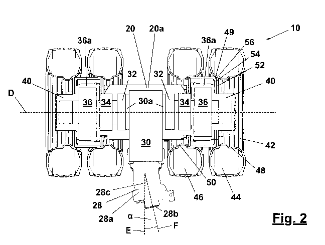
FIG. 2 shows the wheel assembly 10, which is illustrated along a plane
extending
parallel to a longitudinal axis D of the wheel carrier 20.
A drive unit 28, which in the exemplary embodiment shown here is designed as a
hydraulically actuatable axial piston motor arranged outside the housing 20a
of the
wheel carrier 20, and more particularly downstream of the wheel carrier
housing 20a
based on the forward driving direction of the commercial vehicle 80, is
assigned to the
( CA 03016449 2018-08-31
8
wheel carrier 20. The drive unit 28 is aligned relative to the wheel carrier
20 in such a
way that the axis E of the driven shaft 28c of the drive unit 28 is
substantially
perpendicular to the longitudinal axis D of the wheel carrier 20.
The bend typical of axial piston motors between an axis F extending parallel
to the axial
pistons of the axial piston motor 28 and the axis E of the driven shaft 28c
extends in a
plane that extends substantially parallel to the longitudinal axis D of the
wheel carrier 20
in the illustrated exemplary embodiment. As is known per se, the angle of
incidence a
between the axes E and F can be varied by suitable activation of an
appropriate
mechanism 28a of the axial piston motor. The axial piston motor 28 furthermore
comprises hydraulic connections 28b, which are arranged on two opposing sides
of the
axial piston motor 28 relative to the plane that is defined by the two axes E
and F in a
non-parallel alignment of these two axes. Since an extension of the mechanism
28a
perpendicular to the axis F is typically larger than a distance of the
hydraulic
connections 28b perpendicular to the axis F, the aforementioned alignment of
the drive
unit 28 in relation to the wheel carrier 20 makes it possible to keep the
vertical
extension, for example parallel to the axis A (see FIG. 1), of the drive unit
28 small,
since this is determined by the distance of the hydraulic connections 28b.
As is shown in FIG. 2, the driven shaft 28c of the drive unit 28 is engaged
with a first
gear step 30 so as to transmit torque. The first gear step 30 may be designed
as or with
a differential gear. The first gear step 30 has two output ends 30a, wherein
the one
output end 30a points in the direction of the one longitudinal end of the
wheel carrier 20,
and the other output end 30a points in the direction of the other longitudinal
end of the
wheel carrier 20. The two output ends 30a of the first gear step 30 are each
connected
to a clutch 32, which is connected on the output side to a respective second
gear step
34. Each of the two second gear steps 34 is connected on the side located
opposite the
clutch 32 to a service brake 36, which brake devices approved for the
operation of the
commercial vehicle 80 according to the invention on public roads up to speeds
of more
than 25 km/h. The output sides 36a of the service brakes 36 are each connected
to a
CA 03016449 2018-08-31
9
wheel hub 40, which is mounted on the wheel carrier 20 so as to rotate
relative thereto
about an axis of rotation that is substantially parallel to the longitudinal
axis D.
The first gear step 30, the two clutches 32 and the two second gear steps 34
are
accommodated in the interior space I of the housing 20a of the wheel carrier
20.
The two clutches 32 are designed so as to be able to pass torque from the
first gear
step 30 on to the second gear step 34 when the commercial vehicle 80 is moving
at a
speed that is lower than a predetermined shifting speed. In this state, the
commercial
vehicle 80 can be operated as a self-propelled vehicle, which can be driven by
way of
the drive units 28. In this way, the commercial vehicle 80 can assist a
tractor unit, for
example, to which it is connected, in overcoming an uphill grade. If, in
contrast, the
speed of the commercial vehicle 80 exceeds the predetermined shifting speed,
the
clutches 32 open automatically, so that the torque flow from the first gear
step 30 to the
second gear step 34 is interrupted. In this state, the commercial vehicle 80
can be
operated purely as a trailer vehicle, which is moved by way of a tractor unit.
Two main hydraulic lines 38 extend from the hydraulic connections 28b of the
drive unit
28. A first section of the main hydraulic lines 38 is denoted by reference
numeral 38a in
FIG. 1, and the further progression of the main hydraulic lines 38 is
indicated with dash-
dotted lines in FIG. 1. A second section 38b of the main hydraulic lines 38
runs between
the roadway S and the wheel carrier 20. The main hydraulic lines 38 then run
in front of
and behind the swing arm 16 (section 38c), and from there in front of and
behind the
carrier 14, substantially vertically upwardly (section 38d) to the vehicle
frame 82, where
the end sections 38e thereof can be seen.
To enable this progression, according to the invention the swing arm 16 has a
narrow
design in the vehicle width direction. This is made possible, in particular,
by the design
according to the invention of the ball and socket joint 26. More particularly,
the socket of
the ball and socket joint 26 is formed on the side of the power device 22, and
the ball of
the ball and socket joint 26 is formed on the side of the swing arm 16. This
design of the
CA 03016449 2018-08-31
mounting of the power device 22 on the swing arm 16 allows the swing arm 16 to
have
a more space-saving design, and in particular a narrower design in a direction
perpendicular to the drawing plane of FIG. 1, compared to an arrangement of
the ball of
the ball and socket joint 26 on the power device 22 and of the socket of the
ball and
socket joint 26 on the swing arm 16.
It should be added that the socket of the ball and socket joint 24 is assigned
to the
carrier 14, and the ball of the ball and socket joint 24 is assigned to the
power device
22.
A wheel 42 comprising dual tires is provided on each of the wheel hubs 40,
wherein the
dual tires each include an inner tire 46, which is to say adjoining the drive
unit 28, and
an outer tire 44, which is to say arranged on the side of the inner tire 46
facing away
from the drive unit 28. Each of the two outer tires 44 includes a rim 48, and
each of the
two inner tires 46 includes a rim 50. Each of the rims 48 is assigned a wheel
disk 52,
and each of the rims 50 is assigned a wheel disk 54. When the dual tires are
mounted
on the wheel hub 40, the two sub-wheel disks rest 52 and 54 against one
another.
The two wheel disks 52 and 54 can also be referred to as "sub-wheel disks" of
a wheel
disk 56 of the wheel 42. Analogously, the two rims 48 and 50 can be referred
to as "sub-
rims" of a rim 49 of the wheel 42 comprising these two sub-rims 48 and 50.
The two sub-rims 48 and 50, or the sub-wheel disks 52 and 54 thereof, have
different
offsets from one another in the illustrated exemplary embodiment. The offsets
are
selected in such a way that the wheel disk 56 of the rim 49 of the wheel 42 is
arranged
within the extension of the outer tire 44 determined in the longitudinal
direction of the
wheel carrier 20. With the track width of the wheels 42 remaining the same, it
is thus
possible to design the wheel carriers 20 to be longer, so that the interior
space I of the
wheel carrier 20, available for accommodating the aforementioned components,
can
also be designed to be larger.
CA 03016449 2018-08-31
As is apparent from FIG. 1, the angle of incidence 11 between the axis E of
the driven
shaft 28c of the drive unit 28 and the roadway plane S changes when the wheel
carrier
20 is pivoted about the axis B relative to the vehicle frame 82 by way of the
swing arm
16. So as to ensure that the drive unit 28, in particular during steering
maneuvers, does
not collide with components of the commercial vehicle 80 when the wheel
carrier 20 is
fully retracted, and also does not collide with the roadway S, for example,
when the
wheel carrier 20 is fully extended, the angle of incidence 11 is between
approximately
34 and approximately 50 , preferably between approximately 38 and
approximately
46 , and still more preferably approximately 42 when the wheel carrier 20 is
fully
retracted (see FIG. 1), while it is between approximately -19.5 and
approximately -3.5 ,
preferably between approximately -15.5 and approximately -7.5 , and still
more
preferably approximately -11.50 when the wheel carrier 20 is fully extended.
It should be added that the angle y between the self-aligning bearing axis C
and the
driven shaft 28c of the drive unit 28 is between approximately 8 and
approximately 24 ,
preferably between approximately 12 and approximately 20 , and still more
preferably
approximately 16 .