Note : Les descriptions sont présentées dans la langue officielle dans laquelle elles ont été soumises.
CA 03017392 2018-09-10
WO 2017/176567 PCT/US2017/025276
1
SYSTEM WITH REMOTELY CONTROLLED,
PRESSURE ACTUATED TANK VALVE
BACKGROUND
[0001] In some parts of the world that lack gas pipelines, fuel such as
natural gas can be
delivered in high pressure storage tanks on trucks, such as illustrated in
FIG. 1. To maximize the
capacity of a truck trailer, several large capacity tanks are combined with
several smaller
capacity tanks in an assembly. A manifold system is used to pressurize and
depressurize all of
these connected tanks via a common filling hose.
[0002] The connections between the tanks are designed so that in the event
of a fire, the
pressure in the tanks will be purged out of the tanks and into the atmosphere.
In a known purging
process, there is a possibility that a larger tank will backfill into a
smaller tank instead of purging
out to the atmosphere. To avoid this outcome, in the current state of the art,
a pneumatic actuator
is used in some systems, so that when the pressure in the system decreases,
the actuator closes a
valve to isolate the larger tanks from the smaller tanks. However, commonly
used pneumatic
actuators are not rated for the high pressures of the storage tanks;
therefore, regulators must also
be included in the system. The combination of the pneumatic actuators and the
pressure
regulators adds complexity and expense to the currently known systems.
SUMMARY
[0003] In one aspect, a pressurized tank system comprises a first tank, a
second tank, a
manifold, a first conduit connecting the first tank to the manifold, a second
conduit connecting
the second tank to the manifold, a first pressure actuated valve operably
connected to the second
conduit, a third conduit connecting the manifold and the first pressure
actuated valve, and a
fourth conduit connecting the first pressure actuated valve and the second
tank. The first
pressure actuated valve is configured for operation by fluid pressure in the
third conduit.
[0004] In another aspect, a method for controlling fluid flow in a system
is disclosed. The
system comprises a first tank, a second tank, a manifold, a first conduit
connecting the first tank
to the manifold, and a second conduit connecting the second tank to the
manifold. The method
comprises operably connecting a first pressure actuated valve at a junction
between the second
conduit, a third conduit connecting to the manifold, and a fourth conduit
connecting to the
second tank. Moreover, the method comprises introducing fluid into the third
conduit, wherein
CA 03017392 2018-09-10
WO 2017/176567 PCT/US2017/025276
-2-
the fluid has a fluid pressure level. Additionally, the method comprises
automatically opening
the first pressure actuated valve with the fluid when the fluid pressure level
exceeds a threshold
pressure level.
[0005] This disclosure, in its various combinations, either in apparatus or
method form, may
also be characterized by the following listing of items:
1. A pressurized tank system comprising:
a first tank;
a second tank;
a manifold;
a first conduit connecting the first tank to the manifold;
a second conduit connecting the second tank to the manifold;
a first pressure actuated valve operably connected to the second conduit;
a third conduit connecting the manifold and the first pressure actuated valve,
the first
pressure actuated valve being configured for operation by fluid pressure in
the
third conduit; and
a fourth conduit connecting the first pressure actuated valve and the second
tank.
2. The system of item 1, wherein the first tank has a larger volume than
the second tank.
3. The system of any of items 1-2, further comprising a second valve
operably connected to
the first conduit.
4. The system of item 3, further comprising a third valve operably
connected to a fifth
conduit between the manifold and an atmosphere outside the system.
5. The system of any of items 1-4, further comprising a fluid source
connected to the
manifold.
6. The system of any of items 1-5, further comprising a fluid storage
station connected to
the manifold.
7. The system of any of items 1-6, wherein the first pressure actuated
valve is configured for
bi-directional fluid flow between the second and fourth conduits.
8. The system of any of items 1-7, wherein the first pressure actuated
valve opens when a
fluid pressure level in the third conduit reaches a threshold pressure level.
9. The system of item 8, wherein the threshold pressure level is between
about 3,600 psi and
about 4,500 psi.
CA 03017392 2018-09-10
WO 2017/176567 PCT/US2017/025276
-3-
10. A method for controlling fluid flow in a system comprising a first
tank, a second tank, a
manifold, a first conduit connecting the first tank to the manifold, and a
second conduit
connecting the second tank to the manifold, the method comprising:
operably connecting a first pressure actuated valve at a junction between the
second
conduit, a third conduit connecting to the manifold, and a fourth conduit
connecting to the second tank;
introducing fluid into the third conduit, wherein the fluid has a fluid
pressure level; and
automatically opening the first pressure actuated valve with the fluid when
the fluid
pressure level exceeds a threshold pressure level.
11. The method of item 10 further comprising automatically closing the
first pressure
actuated valve when the fluid pressure level falls below the threshold
pressure level.
12. The method of any of items 10-11 wherein fluid flows through the first
pressure actuated
valve from the second conduit to the fourth conduit.
13. The method of any of items 10-12 wherein fluid flows through the first
pressure actuated
valve from the fourth conduit to the second conduit.
14. The method of any of items 10-13, wherein the threshold pressure level
is between about
3,600 psi and about 4,500 psi.
15. The method of any of items 10-14, wherein the first pressure actuated
valve automatically
opens when:
the fluid pressure level in the third conduit is greater or equal to about 0.6
times a fluid
pressure level in the second conduit; and
the fluid pressure level in the third conduit is greater or equal to about 0.6
times a fluid
pressure level in the fourth conduit.
16. The method of any of items 10-15 further comprising operating a second
valve connected
to the first conduit.
17. The method of item 16, further comprising operating a third valve
operably connected to
a fifth conduit between the manifold and an atmosphere outside the system.
18. The method of item 17, further comprising connecting a fluid source to
the manifold.
19. The method of any of items 17-18, further comprising connecting a fluid
storage station
to the manifold.
CA 03017392 2018-09-10
WO 2017/176567 PCT/US2017/025276
-4-
[0006] This summary is provided to introduce concepts in simplified form
that are further
described below in the Detailed Description. This summary is not intended to
identify key
features or essential features of the disclosed or claimed subject matter and
is not intended to
describe each disclosed embodiment or every implementation of the disclosed or
claimed subject
matter. Specifically, features disclosed herein with respect to one embodiment
may be equally
applicable to another. Further, this summary is not intended to be used as an
aid in determining
the scope of the claimed subject matter. Many other novel advantages,
features, and
relationships will become apparent as this description proceeds. The figures
and the description
that follow more particularly exemplify illustrative embodiments.
BRIEF DESCRIPTION OF THE DRAWINGS
[0007] The disclosed subject matter will be further explained with
reference to the attached
figures, wherein like structure or system elements are referred to by like
reference numerals
throughout the several views.
[0008] FIG. 1 is a side perspective view of a known semi-trailer container
loaded with a
plurality of pressure vessels.
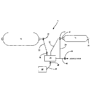
[0009] FIG. 2 is a schematic diagram of an exemplary disclosed system using
a remotely
controlled, pressure actuated tank valve.
[0010] FIG. 3 is a perspective view of an exemplary embodiment of a
remotely controlled,
pressure actuated tank valve of the system of FIG. 2.
[0011] While the above-identified figures set forth one or more embodiments
of the
disclosed subject matter, other embodiments are also contemplated, as noted in
the disclosure. In
all cases, this disclosure presents the disclosed subject matter by way of
representation and not
limitation. It should be understood that numerous other modifications and
embodiments can be
devised by those skilled in the art which fall within the scope and spirit of
the principles of this
disclosure.
[0012] The figures may not be drawn to scale. In particular, some features
may be enlarged
relative to other features for clarity. Moreover, where terms such as above,
below, over, under,
top, bottom, side, right, left, etc., are used, it is to be understood that
they are used only for ease
of understanding the description. It is contemplated that structures may be
oriented otherwise.
-5-
DETAILED DESCRIPTION
[0013] This disclosure describes a system including a remotely operated
switch or valve that
actuates to isolate a tank from a bank of tanks in the event of a loss of
pressure in a system, such
as when a fire triggers a purging process. Other applications for a disclosed
system include uses
during filling or unloading of a tank or bank of tanks.
[0014] FIG. 2 shows a schematic diagram of a pressurized tank system 10 in
which tank 12
has a larger volume than tank 14. Valve 16, valve 18 and valve 20 are
controlled by an operator,
such as manually or by computer control. Pressure-actuated valve 22
automatically opens and
closes in response to pressure in line 24. Because pressure-actuated valve 22
is not directly
opened and closed by an operator or computer-controlled actuator, for example,
it is sometimes
referred to as being "remotely operated." Because an operator does not need to
open and close
pressure-actuated valve 22 directly, the described concept reduces manual
handling in hard-to-
reach areas and decreases the chance for human error.
[0015] The current disclosure uses the term "gas" to generally refer to a
gaseous phase fluid
under pressure. However, it is to be understood that other fluids can also be
stored in system 10.
Moreover, the current disclosure uses the term "tank" to generally refer to a
pressure vessel, such
as a composite filament wound pressure vessel. Details relevant to the
formation of exemplary
pressure vessels 12, 14 are disclosed in U.S. Pat. No. 4,838,971, titled
"Filament Winding
Process and Apparatus". However, it is to be understood that other containers
may also be used.
[0016] In an exemplary process for filling tanks 12 and 14, a conduit 26
connects the
manifold 28 to a gas source (shown as gas source/station 44). Manually or
otherwise, valve 18 to
the atmosphere is closed, and valves 16, 20 and 46 are opened. Pressurized
fluid from the gas
source 44 flows through manifold 28 and open valve 16, through conduit or line
30, and through
open valve 20 to fill tank 12. Moreover, pressurized fluid from the gas source
44 flows through
manifold 28 and conduits or lines 24 and 32 to pressure-actuated valve 22,
which is initially
closed. Conduit or line 24 is a dedicated line for the operation (e.g.,
opening and closing) of
pressure-actuated valve 22 by fluid pressure in line 24; line 24 connects
manifold 28 and
pressure-actuated valve 22. In contrast, conduit or line 32 is a line for
filling and emptying tank
14 via manifold 28.
Date Recue/Date Received 2022-06-30
CA 03017392 2018-09-10
WO 2017/176567 PCT/US2017/025276
-6-
[0017] When pressure in line 24 is sufficient at pressure-actuated valve
22, the pressure in
line 24 opens pressure-actuated valve 22 so that flow through line 32 can then
fill tank 14. After
tanks 12 and 14 are filled, the operator closes valve 20 to tank 12. The
operator opens valve 18 ¨
on conduit or line 48 connecting manifold 28 and an atmosphere outside system
10 -- to the
atmosphere. Opening valve 18 causes flow lines 24, 30 and 32 to lose pressure.
Because of the
loss of pressure in line 24, the pressure in line 24 drops to a level that is
insufficient for keeping
pressure-actuated valve 22 open, and so pressure-actuated valve 22 of tank 14
closes. With
valve 20 and pressure-actuated valve 22 closed, tanks 12 and 14 remain filled.
Then, the conduit
26 can be disconnected from the gas source 44.
[0018] For depressurizing and emptying of the tanks 12 and 14, the conduit
26 in one
application is between manifold 28 and a station (shown as gas source/station
44) that will store
the gas for future consumption. In an exemplary method, a defueling station
valve 46 along
conduit 26 between the manifold 28 and the station 44 is initially closed. The
operator closes
valve 18 to the atmosphere and opens valves 16 and 20 allowing gas in line 30
to flow from the
high pressure tank 12 and through the manifold 28 to pressurize the lines 24
and 32. The
pressure in line 24 opens pressure-actuated valve 22 ¨ in a case wherein the
pressure in tank 12 is
greater than the pressure in tank 14 (and other conditions for opening
pressure-operated valve 22
are met) -- thereby allowing gas from tank 12 to flow into tank 14 through
line 32. This flow
ceases upon reaching a pressure equilibrium balance in tanks 12 and 14. When
the defueling
station valve 46 is opened along conduit 26, both tanks 12 and 14
depressurize, thereby emptying
into the gas storage station 44.
[0019] In the case of a fire wherein tanks 12 and 14 are filled, a user may
manually open
valves 16, 18 and 20 or a sensor can automatically open valves 16, 18 and 20,
for example, to
cause purging of the contents of tank 12 and depressurization in lines 24, 30
and 32. The
depressurization of line 24 causes pressure-actuated valve 22 to automatically
close when there
is insufficient pressure in line 24 to keep pressure-actuated valve 22 open.
This automatic
closure of pressure-actuated valve 22 therefore isolates smaller tank 14 from
larger tank 12,
thereby preventing backflow of pressurized gas from tank 12 to tank 14. In a
case where an
undesirable amount of gas remains in tank 14, tank 14 may be purged through
boss 34 in a
separate operation.
CA 03017392 2018-09-10
WO 2017/176567 PCT/US2017/025276
-7-
[0020] In an assembly of multiple tanks such as shown in FIG. 1, gas flow
lines for some of
the tanks may be difficult to access for opening and closing valves. Thus, the
provision of a
pressure-actuated valve 22 that is operated entirely by gas flow through a
dedicated valve
actuation pressure line 24 allows for automatic opening and closing of the
pressure-actuated
valve 22 in response to the pressure of gas flow in line 24. Referring to FIG.
3, such a pressure-
actuated valve 22 may use a baising member (e.g., a spring) that operates in
response to the
pressure in line 24, to open or close port 36 in valve 22 to line 32. A
suitable pressure-actuated
valve 22 is commercially available as a 3/4 inch, bi-directional pneumatically
actuated valve, from
Clark Cooper, a division of Magnatrol Valve Corp., of Roebling, New Jersey.
[0021] In an exemplary embodiment, pressure-actuated valve 22 is calibrated
to open and
close port 36 at a desired pressure value or range of pressure values of gas
flow in line 24, as
consistent with the filling and depressurizing methods discussed above. This
pressure value or
range can be much greater than the pressures that can be accommodated with
conventional
pneumatic actuators. For example, conventional pneumatic actuators are
generally operable up
to about 500 psi (pounds per square inch). Thus, the pneumatic actuators are
generally used with
complicated, cumbersome and expensive pressure regulators that decrease line
pressures to the
low range that can be used with the conventional pneumatic actuator. In
contrast, pressure-
actuated valve 22 can be a mechanical apparatus that is able to withstand
typical pressure levels
in system 10, such as up to 5,000 psi for the storage of compressed natural
gas, for example.
Moreover, valve 22 can operate in temperatures between about -50 degrees F and
about 180
degrees F, which is suitable for the storage of compressed natural gas, for
example. While
exemplary values are given for compressed natural gas, system 10 is also
suitable for the storage
of other fluids, including hydrogen gas, for example. For the storage of
hydrogen gas, pressure-
actuated valve 22 is designed or selected to withstand pressure levels up to
22,000 psi, for
example, and temperatures between about -50 degrees F and about 180 degrees F.
It is
contemplated that still other operation ranges of pressures and temperatures
may be suitable for
other fluids, such as helium, nitrogen, neon, or argon, for example.
[0022] FIG. 3 shows a view of valve 22, which is configured to be connected
in system 10 at
a junction of line 32, line 24, and line 38 (fluidly connecting valve 22 and
tank 14 to manifold 28
and the atmosphere). Line 32 is connected to port 36 of valve 22. Line 24 is
connected to port
40 of valve 22. Line 38 is connected to port 42 of valve 22. The pressure of
fluid in line 32 is
CA 03017392 2018-09-10
WO 2017/176567 PCT/US2017/025276
-8-
referred to herein as P32. The pressure of fluid in line 24 is referred to
herein as P24. The
pressure of fluid in line 38 is referred to herein as P38. The pressure of
fluid in tank 12 is referred
to herein as P12. The pressure of fluid in tank 14 is referred to herein as
P14. In many cases, P12=
P32 and P14= P38. In an exemplary embodiment, valve 22 is bi-directional
between port 36 and
port 42, allowing fluid flow from line 32 to line 38 and vice versa. In an
exemplary
embodiment, valve 22 is normally closed. When P24 reaches a threshold pressure
level (PT),
valve 22 opens, allowing flow between lines 32 and 38. In an exemplary
embodiment, PT is
between about 100 psi and about 4,500 psi, for example. Even more
particularly, PT can be
between about 3,600 psi and about 4,500 psi. The flow direction will be
determined by P32 and
P38. When P32> P38, the fluid will flow through valve 22 from line 32 to line
38. Conversely,
when P32 < P38, the fluid will flow through valve 22 from line 38 to line 32.
In an exemplary
embodiment, PT is set so that valve 22 opens when P24 > 0.6P38 and P24 >
0.6P32. In an
exemplary embodiment, pressure-actuated valve 22 automatically closes when P24
falls below
PT. In an exemplary embodiment, valve 22 remains closed when P24 < 0.35P38;
moreover, valve
22 remains closed when P24 < 0.45P32. While exemplary ratios of 0.35, 0.45,
and 0.60 are
described, it is to be understood that other ratios may also be suitable; the
ratio values can be
changed by changing the configuration of internal structures of the valve.
These numerical
relationships represent the "lag" or "dead zone" in a valve ¨ ranges of
pressures on the circuit in
which behavior of the valve is not definitive. These ranges may be influenced
by various factors
including friction and spring forces, for example.
[0023] Although the subject of this disclosure has been described with
reference to several
embodiments, workers skilled in the art will recognize that changes may be
made in form and
detail without departing from the scope of the disclosure. In addition, any
feature disclosed with
respect to one embodiment may be incorporated in another embodiment, and vice-
versa. For
example, while a particular embodiment of the disclosed system is shown, it is
contemplated that
one of valves 16 and 20 could be eliminated in a particular implementation of
the disclosed
system so that a single valve controls fluid communication between tank 12 and
manifold 28.
Moreover, in other embodiments, it is contemplated that additional valves may
be added, for
example to offer more control points in system 10.