Note : Les descriptions sont présentées dans la langue officielle dans laquelle elles ont été soumises.
AUTOMATIC BAGGING MACHINE HAVING
ROLLSTOCK SUPPORT SPOOL
BACKGROUND OF TILE INVENTION
1. Field of the Invention
[0001] The invention relates generally to rollstock supports onto
which
continuous webs of bags can be wound after manufacture and from which
rollstock
can subsequently be unwound during a bag filling operation. The invention
additionally relates to an unwinder assembly incorporating such a rollstock
support
and to an automatic bagging machine incorporating such an unwinder assembly.
2. Discussion of the Related Art
[0002] Automatic and semi-automatic bagging machines are available for
filling pre-formed bags with discrete items, such as produce items in the form
of
avocados, potatoes, onions, carrots, etc. The degree of automation and the
accompanying bag filling rates vary dramatically from machine-to-machine. Some
machines convey bags from a loading station, where individual bags or groups
of
bags are manually placed on the machine, either individually or in a magazine,
to a
filling station where the bags are filled using filling equipment, to a
discharge
station where the bags are manually or automatically discharged from the
machine
and closed -- often manually. These machines may require at least one
dedicated
operator per machine and operate quite slowly. An example of these machines is
a
so-called carousel-style bagger in which the bags are manually hung on a
rotating
turret at a loading station, and the turret then rotates through a filling
station into a
discharge location.
1
CA 3020775 2018-10-15
[0003] Fully automated machines are available that do not require
manual
intervention on a per-bag basis. Automated bagging machines include so-called
"rollstock baggers" that handle a continuous web or chain of interconnected,
fully-
formed or partially-formed bags wound onto a roll as "rollstock". If the bags
are
partially formed, the machine completes the converting or forming of bags
prior to
filling. If the bags are fully formed, the machine simply fills the bags and
separates
them from the web. In either event, the machine receives a web of material
from
the rollstock, fills the bags, separates the bags from the web, and discharges
the
filled bags from the machine, sometimes after sealing or otherwise closing the
filled bags.
[0004] An example of an automatic bagging machine is one that
accommodates a continuous strip or line formed from individual bags that is
each
connected at its upper end to a continuous carrier band or line, much as
laundry is
suspended from a clothesline. One such machine is available from Schur Star
Packaging Systems, Inc. under the model numbers 2040 or 3020. In this machine,
a line supporting spaced individual bags is conveyed through the bagging
machine,
where the individual bags are filled, separated from the line, and possibly
closed
such as by heat sealing. The web, including the bags and line, is formed from
during the bag manufacturing process, and is piled into cartons in a fan or Z-
fold
manner. Frequent stoppage is required to replace an empty carton with a full
carton. The web also typically must be reoriented from a horizontal
orientation to
a vertical orientation as it is fed into the bagging machine with the aid of a
relatively complex guide mechanism.
2
CA 3020775 2018-10-15
[0005] Higher capacity automatic bagging machines also are available
in the
form of so-called -rollstock baggers." Rollstock baggers include a bagging
machine and an integrated unwinder assembly. The bagging machine typically
receives a v-folded web of unformed, partially formed, or near- fully-formed
bags
from "rollstock" wound onto a vertically extending roll on an unwinder
assembly
positioned adjacent an inlet end or infeed of the bagging machine. In the case
of a
"horizontal rollstock bagger", the roll and web extend vertically, and the
bags are
filled from above. In this type of machine, the he web is conveyed
horizontally
through the bagging machine, where the side seals of the bags are partially
formed
or partially separated, the bags are filled, completely separated from one
another,
possibly closed, and discharged to a discharge conveyor or the like. Rollstock
baggers have the advantage of operating fully automatically and very rapidly
with
no operator intervention and relatively little operator oversight. The
rollstock can
be formed from several thousand conjoined bags, permitting operation between
changeovers for much longer periods of time than is the case with baggers
handling
individual bags manually hung, placed in magazines, or suspended from a line.
[0006] Rollstock intended for use with rollstock baggers must be wound
onto
an underlying core uniformly so that the rollstock being unwound from the core
during a bagging process remains at a uniform height as it is conveyed into
the
bagging machine and so that no layers project beneath the bottom of the core
so as
to be crushed when the core is deposited into the unwinder assembly. Winding
rollstock in this fashion is not particularly difficult with respect to non-
gusseted
polymer bags or other bags having a generally uniform thickness from their
bottom
3
CA 3020775 2018-10-15
=
end to their top end. However, winding rollstock uniformly onto a core is
difficult
with respect to bags that are thicker at one point along the vertical extent
than
another.
100071 An example of such a bag is a bottom gusseted pouch-style bag,
such
as the one manufactured by Volm Companies, Inc. under the name "HALF-N-
HALF POUCH." This bag is characterized by an upper film portion which may or
may not have a zip lock or other closure and a bottom-gusseted lower mesh
portion.
Except in the area of the zip lock, where it is thicker, the upper portion of
the bag
consists of only two layers. The gusseted lower portion of the bag, however,
consists of four layers over most of its extent and has six layers along a
portion
where the mesh and film portions of the outer walls of the bag overlap at the
apex
of the gusset. The lower portion of this bag thus is, on average, several
times
thicker than the upper portion of the bag. When a continuous web of such a bag
is
wound onto a core, the web tends to walk or telescope off one end of the core
so
that the outermost bags of the resulting rollstock extend well above the
innermost
bags. As a result of this walking or telescoping, bottom-gusseted, pouch-style
bags
and other bags varying considerably in thickness along their length cannot be
employed as rollstock on automatic baggers.
[0008] These bags thus either must be separated from one another at the
point of manufacture, shipped in stacks in boxes, and loaded onto bagging
machines manually. All of these operations add substantial time and expense to
the
handling and bagging processes and prevent the filling of the bags using fully
4
CA 3020775 2018-10-15
automated machines such as horizontal rollstock baggers. Alternatively, the
bags
can be attached to a carrier band or line during the manufacturing process and
filled
as described above. However, as mentioned above, a given web supplied to such
a
machine can contain only a few hundred bags and must be folded into cartons.
100091 The need therefore has arisen to provide a mechanism
facilitating the
uniform winding of webs of bags of non-uniform thickness along their length to
form rollstock while maintaining a uniform rollstock height.
[0010] The need additionally has arisen to provide an unwinder
assembly
compatible for use with a fully-automated bagging machine that delivers a
continuous web of bags of the aforementioned type into the bagging machine at
a
uniform height.
100111 The need additionally has arisen to provide an automatic bagger
that
can fill bags of the aforementioned type that are provided in the form of
rollstock.
SUMMARY OF THE INVENTION
10012] In accordance with an aspect of the invention, at least some of
the
noted needs are met through the provision of a rollstock support spool having
a
hollow core and first and second opposed rims. The hollow core has opposed
axial
ends, an inner peripheral surface defining a tubular opening configured for
mounting over a spindle, and an outer peripheral surface configured to support
rollstock. The rims are located at or near the first and second ends of the
core,
respectively. Each of the first and second rims has an inner axial surface, an
outer
axial surface, an inner peripheral surface defining an opening that is aligned
with
CA 3020775 2018-10-15
the opening in the core, and an outer peripheral surface. A radial spacing
between
the outer peripheral surface of the core and the outer peripheral surface of
each of
the rims is greater than a maximum thickness of the rollstock.
[0013] The effective length of the spool, defined as an axial spacing
between
the inner surfaces of the first and second rims, may be between 6" and 30" and
more typically between 6" and 24". This effective length may be between 1/8"
and
1/2" longer than a height of the rollstock.
[0014] The rollstock may be formed from bottom-gusseted, pouch-style
bags.
100151 In accordance with another aspect of the invention, an unwinder
assembly for an automatic bagging machine is provided that can accommodate a
spool as configured above. The unwinder assembly includes a table, a driven
spindle supported on the table, and the rollstock support spool. The table may
be
mounted on a movable frame that can be raised and lowered by a drive motor and
a
drive arrangement. The motor may comprise an electric motor, and the drive
arrangement may comprise a screw drive that is threadedly coupled to the
frame. A
monitor may be provided that monitors a height of the web of bags being
withdrawn from the spool and that generates signals that are used to control
the
motor to adjust the position of the spool relative to the frame to maintain
the height
of the web of bags essentially constant during bagging. The monitor may be a
photoeye.
6
CA 3020775 2018-10-15
[00161 In accordance with yet another aspect of the invention, an
automatic
bagger is provided having an unwinder assembly configured as described above.
The bagging machine of this bagger may be a horizontal rollstock bagger.
[00171 These and other objects, advantages, and features of the
invention
will become apparent to those skilled in the art from the detailed description
and
the accompanying drawings. It should be understood, however, that the detailed
description and accompanying drawings, while indicating preferred embodiments
of the present invention, are given by way of illustration and not of
limitation.
Many changes and modifications may be made within the scope of the present
invention without departing from the spirit thereof, and the invention
includes all
such modifications.
BRIEF DESCRIPTION OF THE DRAWINGS
[0018] Preferred exemplary embodiments of the invention are
illustrated in
the accompanying drawings, in which like reference numerals represent like
parts
throughout, and in which:
100191 FIG. 1 is a somewhat schematic side-elevation view of a
horizontal
rollstock bagger incorporating an unwinder assembly constructed in accordance
with an embodiment of the invention;
[00201 FIG. 2 is a top plan view of the bagger of FIG. 1;
100211 FIG. 3 is a side-elevation view of a bag filled by the bagger
of FIGS.
land 2;
7
CA 3020775 2018-10-15
=
100221 FIG. 4 is a sectional and elevation view of the bag taken
generally
along the line 4-4 in FIG. 3;
100231 FIG. 5 is a side-elevation view of a continuous web of the bags
of
FIGS. 3 and 4, joined end-to-end;
100241 FIG. 6 is a side-elevation view of the unwinder assembly of the
bagger of FIGS. 1 and 2 and of the infeed end of the bagging machine;
100251 FIG. 7 is an isometric view of the unwinder assembly of FIG. 6
and
of the adjacent portions of the bagging machine;
100261 FIG. 8 is a top plan view of the unwinder assembly of FIGS. 6
and 7
and of the adjacent portions of the bagging machine;
100271 FIG. 9 is a sectional elevation view of a portion of the
unwinder
assembly of FIGS. 6-8; and
100281 FIG. 10 schematically illustrates a control system of the
bagger of
FIGS. 1 and 2.
DETAILED DESCRIPTION
100291 An embodiment of FIGS. 1 and 2 of the invention now will be
described, including an unwinder assembly of a horizontal rollstock bagger and
an
associated spool that deliver a web of bottom gusseted pouch-style bags to the
bagging machine of the bagger. It should be understood, however, that many or
all
of the concepts discussed herein are applicable to other bags of variable
thickness
along their length, and that the rollstock support spool as disclosed herein
and the
8
CA 3020775 2018-10-15
associated unwinder assembly can be used with a variety of other bagging
machines other than the horizontal rollstock bagger disclosed herein.
[00301 Referring now to the drawings and initially to FIGS. 1 and 2, a
rollstock bagger 10 is schematically illustrated that incorporates a bagging
machine
12 and an unwinder assembly 150 constructed in accordance with the present
invention. The bagging machine 12 has a stationary frame 16. A conveyor 18,
formed from upstream and downstream sections 18A and 18B, is supported on the
frame 16 and transports a web 140 of bags 100 from the unwinder assembly 150
and through the bagging machine 12. Moving from the upstream or infeed end to
the downstream or discharge end, the bagging machine 12 includes a dancer
roller
assembly 20 and a perforator 21 located upstream of the upstream conveyor 18A,
a
heated cutter bar 22 mounted on the frame 16 near a midpoint of the bagging
machine 12, a tilling station 24 located downstream of the cutter bar 22 at
the
downstream end of the upstream conveyor section 18A, a closer 25 located
adjacent the downstream conveyor section 18B, and a discharge conveyor 26
located beneath and extending downstream from the downstream conveyor-section
18B. Bagger 10 is controlled by an electronic controller 300, shown
schematically
in FIG. 10. The horizontal bagger 10, excluding the unwinder assembly 150 and
associated components, may be a commercially-available bagger manufactured,
for
example, by Manter International, BV of Emmen Netherlands under the series RSB
P.
9
CA 3020775 2018-10-15
[00311 Still referring to FIGS. 1 and 2, each conveyor section 18A and
18B
takes the form of a pair of endless belts 28, 30 that convey the upper end of
the
web140 of bags 100 horizontally through the bagging machine 12. The conveyor
sections 18A and 18B are driven independently of one another, so that the
downstream section 18B can be driven while upstream section 18A is stationary
to
separate a recently filled bag 100 from the end of the web 140. The conveyor
sections 18 18A and 1813 are driven by one or more electric motor(s) 302 (FIG.
10)
under control of the controller 300.
[00321 Referring to FIGS. 1, 2 and 8, the perforator 21 is located
between the
dancer roller assembly 20 and the upstream end of conveyor section 18A. It may
include a reciprocating serrated knife and an anvil located on opposite sides
of the
web 140. The knife can be driven toward and away from the anvil to perforate
the
edges of adjoined bags 100 along a vertical line extending downwardly about 2"
to
3" from the top of the web 140.
[0033] Referring to FIGS. 1, 2, and 6-8, the dancer roller assembly 20
includes a number of longitudinally and transversely-spaced rollers 32, each
having
opposed ends rotatably mounted on a subframe 34 of frame 16. Some of the
individual rollers 32 are mounted on a transversely movable portion 36 of the
subframe 34 in a manner that is well-known to maintain proper tension on the
web
of bags140 while accommodating slight mismatches in spool and belt motion.
[0034] Referring to FIGS. 1 and 2, the cutter bar 22 is a vertically-
extending
(heat) knife mounted on the frame 16 at a cutting station located upstream of
the
CA 3020775 2018-10-15
filling station 24. Cutter bar 22 can be driven by a drive, such as a
pneumatic
cylinder to reciprocate transversely toward and away from the from the
conveyor
18 to separate the bottom portions of each adjacent pair of bags 100 from one
another as the web of bags 140 moves intermittently through the cutting
station.
After this cutting, the bags 100 remain connected at their upper portions at
the
perforated section formed by perforator 21 with sufficient strength to permit
the
partially-separated web140 to be pulled downstream toward the filling station
24 by
the conveyor section 18A.
100351 Still referring to FIGS. 1 and 2, the filling station 24
includes at least
a hopper 40 located above the downstream end of conveyor section 18A. Filling
station 24 also may include additional equipment (not shown) configured to
discharge batches of a predetermined volume or predetermined weight of items
into
the hopper 40 in preparation for filling the bags 100. These items may, for
example, comprise produce items such as avocados, potatoes, carrots, or
onions.
The bottom 42 of the hopper 40 is selectively opened by the controller 300
when an
open bag 100 is aligned with the hopper bottom 42. An opening assembly, not
shown, is located under the hopper 40. The opening assembly selectively opens
each bag 100 after it is positioned under the hopper 40, holds the bag 100
open
while the bag is filled, and then closes the bag 100. The upstream conveyor
section 18A then remains stationary while the downstream conveyor section 18B
is
driven to separate the filled bag 100 from the web 140 and conveys that bag
100
away from the filling station 24.
11
CA 3020775 2018-10-15
[0036] Finally, at the discharge end of the bagging machine 12, each
filled
bag 100 is closed by the closer 25, which may for example, heat seal the upper
end
of the opposed walls of the bags together and/or close a zip lock or other
integrated
closure mechanism. The filled and closed bag 100 is then discharged from the
downstream end of the conveyor section 1813, either by being cut at it its
upper end
by the closer or by being conveyed off the downstream end of the conveyor
section,
and is deposited onto the discharge conveyor 26. The discharge conveyor 26
then
conveys the filled bags 100 downstream for further handling.
[00371 The bags 100 may be of any of a number of bag heights ranging
from
6- or lower to 24" or higher. As mentioned below, the unwinder assembly 150 is
configured to accommodate rollstock 142 formed from bags that vary
considerably
in thickness along their length. All-film bags having zip-locks exhibit some-
such
variation, and would be benefitted by the unwinder assembly 150 disclosed
herein.
The disclosed bags 100, however, may be multi-substrate, bottom-gusseted, and-
or
pouch-style bags and are especially well-served by the combination of the
unwinder assembly and spool disclosed herein.
[0038] Referring now to FIGS. 3 and 4 the illustrated bag 100 is a
relatively
small-capacity bottom-gusseted, pouch-style bag configured to store produce
items
such as avocados. It is sold by Volm Companies, Inc. under the mark HALF-N-
HALF POUCH. The illustrated bag 100 has a capacity of two lbs. and an unfilled
width of about 12". The bag 100 has an upper, film portion 102 and a lower,
mesh
portion 104. The upper portion 102 has front and rear walls 106 and 108. A
handle
12
CA 3020775 2018-10-15
110 and a closure 112 are provided in the upper portion 102 of the bag 100.
The
handle 110 takes the form of aligned openings formed through the upper portion
of
the front and rear walls 106 and 108, respectively. The closure 112 comprises
a
zipper or zip-lock disposed beneath the handle 110.
[0039] Each of the front and rear walls 106 and 108 is formed from a
continuous strip of the film material, extending from the bottom end of the
wall to
the top end. Notches or tear areas 114 may be provided above the closure 112
to
permit the top of the bag 100 to be torn off by the end consumer. The front
and
rear walls 106 and 108 are joined to one another along left and right
vertically-
extending side seams 116, 118 formed by thermally bonding the walls 106 and
108
together at their opposed left and right edges 120 and 121
[0040] Still referring particularly to FIGS. 3 and 4, the bottom
portion 104 of
the bag 100 is gusseted to permit expansion of the bag 100 when it is filled
with
materials and, thus, to increase the volumetric capacity of a bag 100 of a
given
height and width. The bottom gusset is a so-called "single-gusset" in the
present
embodiment, having four panels 124, 126, 128, and 130. The outer panels 124
and
126 form the outer side walls of the lower portion 104 of the bag 100, and the
inner
panels 128 and 130 form a gusset having an apex 132. The upper end of each of
the outer panels 124 or 126 is heat sealed to the interior surface of the
bottom end
portion of the associated upper wall 106 or 108 via a first horizontally-
extending
seam. Each of the left and right side edges of the first through fourth panels
is
thermally bonded to the corresponding edge of the other three panels by the
side
13
CA 3020775 2018-10-15
seams 116 and 118, which extend the entire height of the bag 100. The upper
ends
of the inner panels 128 and 130 extend above the bottoms of the walls 106 and
108,
and thus also are bonded to the film material of the front and rear walls 106
and
108 at seams 134 and 136.
[0041]
Referring to FIG. 5, the bags 100 constructed as described above are
formed as a continuous web 140 of conjoined bags 100 joined edge-to-edge by
the
side seams 116 and 118 of adjacent bags 100. The web140 is wound onto a spool
160 at the end of the manufacturing process to form rollstock 142, best seen
in FIG.
9. Because the bags 100 forming this rollstock 142 have only two layers at
their
upper ends and at least four layers at the lower ends, and six layers where
the mesh
material is sealed to the film material, each bag 100 is considerably thicker
at its
lower end than at its upper end. In fact, the thickness of an empty bag 100
varies
about 0.075" between the thickest and thinnest portion of the bag. That
variation in
thickness may vary significantly based on factors such as the thickness of the
film
used in the bags. This unevenness accumulates as successive layers of bags
100,
totaling up to 750 layers or more in a roll having 3000 bags, are wound onto
the
spool 160. The resulting rollstock 142 is significantly thicker at its bottom
end then
its top end. This unevenness tends to cause successive layers of the rollstock
142
to tend to "walk" or telescope axially of the spool 160 as the web 140 is
wound
onto the spool 160. The provision of a spool 160 (detailed below) rather than
a
simple core for supporting the rollstock 142 prevents excessive telescoping of
the
rollstock 142, as discussed in more detail below.
14
CA 3020775 2018-10-15
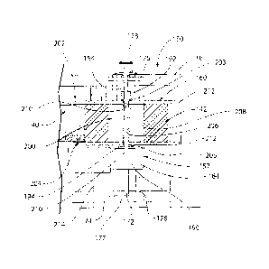
[0042] Turning now to FIGS. 6-9, the unwinder assembly 150 includes a
table 152 (FIGS. 7 and 9) that is mounted on a vertically movable table
support
frame 162, a driven spindle 154 that is supported on the table 152, and a
rollstock
support spool 160 that is supported on the spindle 154. The table 152 of this
embodiment includes a motor housing 164 and associated mounting brackets that
are collectively mounted on the table support frame 162 as best seen in FIGS.
7 and
9. The table support frame 162 includes a support plate 166 and upper and
lower
mounting plates 168, 170. The support plate 166 extends vertically so as to
have
front and rear surfaces, with the table 152 being mounted on the lower end of
the
front surface of the support plate 166. The upper and lower mounting plates
168
and 170 are mounted on the rear surface of the support plate 166 in a
vertically-
spaced relationship with respect to one another.
[0043] The table support frame 162 is mounted on the main frame 16 of
the
bagging machine 12 so as to be fixed from lateral or transverse movement but
so as
to movable relative to the frame 16. Table height adjustment is useful both
during
set-up to accommodate rollstock of various heights and during a bagging
operation
to accommodate relatively small fluctuations in the height of the web140 being
unwound from the spool 160. In the illustrated embodiment, first and second
guide
rods 174 and 176 collectively permit vertical movement of the table support
frame
162 and table 152 relative to the frame 16 under operation of a screw drive
172.
The screw drive 172 extends vertically through aligned threaded holes in the
center
of upper and lower support brackets 175 and 177 that are fixed to the frame 16
and
the upper and lower mounting plates 168 and 170. Each of the guide rods 174
and
CA 3020775 2018-10-15
=
176 extends vertically through aligned holes in a respective end portion of
the
support brackets 175 and 177 and the mounting plates 168 and 170. Due to this
arrangement, rotation of the screw drive 172 causes the threaded plates 168
and 170
to move vertically, with the guide rods 174 and 176 constraining the motion to
a
vertical plane.
100441 The screw drive 172 is selectively driven to rotate by an
electric table
height adjustment motor 178 mounted on top of the infeed end of the frame 16.
The motor 178 may be controlled by the controller 300 of FIG. 10. The motor
178
may be actuated either to accommodate different rollstock heights during a set-
up
process, or during bag filling under feedback from a bag web height monitor
that
monitors the height of the web 140 of bags being fed into the drive belts 28,
30
from the dancer roller assembly 20. In the present embodiment, that monitor
takes
the form of a photoeye 180 that is mounted on the side of the frame 16 as best
seen
in FIG. 6 and that is coupled to the controller 300 as shown in FIG. 10. The
illustrated assembly has a maximum adjustment stroke of about 21" for set-up
purposes and an operational adjustment stroke under control of the photoeye
180 of
about 1/4" to 1", and more typically of about 1/2".
100451 Still referring to FIGS. 6-9 and particularly to FIG. 9, the
spindle 154
is rotatably supported on and extends upwardly from the motor housing 164 of
table 152. The illustrated spindle 154 has a diameter of less than 3" to
accommodate the 3" ID core 190. The spindle 154 is driven by an electric
spindle
drive motor 190 contained within the motor housing 164. The motor 190 may be
16
CA 3020775 2018-10-15
controlled by the controller 300 of FIG. 10. The spindle 154 extends
sufficiently
far above the table 152 to receive the spool 160. The spool 160 is supported
on a
collar 194 that is clamped onto the spindle 154 above the motor housing 164.
The
provision of the clamp permits the vertical position of the collar 194 on the
spindle
154 to be adjusted during changeover operations in order to provide additional
spool height adjustment beyond that provided by the screw drive 172. The spool
160 is rotationally fixed to the spindle 154 by a drive pin (not shown)
extending
upwardly from the collar 194 into an opening in a lower core plug 205 of the
rollstock support spool 160.
100461 Referring to FIGS. 7-9, the rollstock support spool 160
includes a
hollow core 200 and first and second (upper and lower) rims 202 and 204. The
first
and second rims 202 and 204 are attached to the core 200 at or near respective
axial
ends of the core 200 via respective core plugs 203 and 205. The rims 202 and
204
act as guides or barriers during a rollstock winding process that prevent
rollstock
142 from telescoping off the ends of the spool 160. The resulting uniformly-
wound
rollstock 142 can be used on the horizontal rollstock bagger 10. The effective
height of the illustrated spool 160, defined as the axial spacing between the
rims
200 and 204, is about 6-1/4" inches high because the spool 160 is configured
to
support rollstock formed from 6" high bags. Effective spool heights of more
than
24" are contemplated, however, for accommodating higher bags of up to 24". It
is
beneficial, however, that the effective spool height be no more than 1/2"
greater
than the height of the rollstock, and more typically, no more than 1/4"
greater than
17
CA 3020775 2018-10-15
the height of the rollstock. This relatively small differential assures
relatively even
winding of the rollstock 142 onto the core 200.
[00471 Referring to FIG. 9, the core 200 has an inner peripheral
surface 206
defining a tubular opening configured for mounting over the spindle 154, and
an
outer peripheral surface 208 configured to support the rollstock 142. The core
200
of this embodiment has an inner diameter of 3" and an outer diameter of 4".
The
core 200 and rims 202 and 204 may be made of cardboard, plastic, wood, metal,
or
any other suitably strong, durable material.
100481 Still Referring to FIGS. 7-9, each rim 202 or 204 has an inner
peripheral surface 210 and an outer peripheral surface 212. The inner
peripheral
surface 210 of each rim 202 or 204 is affixed to the respective end of the
core 200
by a respective core plug 203 or 205. Each rim 202, 204 is considerably wider
than the core 200 and, in fact, is configured to form a radial spacing between
the
outer peripheral surface 208 of the core 200 and the outer peripheral surface
212 of
the rim 202 or 204 that is greater than a maximum thickness of the rollstock
142.
Rim diameters of 10" to 24" or more with resultant radial spacings of 4" to
20" or
more are contemplated. The rims 202 and 204 of the illustrated embodiment each
have a diameter of 24," resulting in a radial spacing between the outer
peripheral
surface 208 of the core 200 and the outer peripheral surface 212 of the rims
202 and
204 of 20." The spool 160 can support up to 750 layers of the bottom-gusseted,
pouch-style bags 100 described above.
18
CA 3020775 2018-10-15
100491 In operation of the unwinder assembly 150, the assembly 150 is
readied for operation by mounting a spool 160 on the collar 194 after
positioning
the collar at a desired location on the spindle 154, and then placing the top
endcap
192 over the spool 160. The screw drive 172 is operated by motor 178 as
necessary
at this time to align the top of the rollstock 142 with the belts 28 and 30 of
conveyor 18. The end of the web 140 of bags forming the rollstock 142 is then
manually threaded around the dancer rollers 32, over an idler roller 214, and
into
the conveyor 18. The bagging machine 12 then is operated under control of the
controller 300 of FIG. 10 to unwind the web 140 of bags 100 from the spool 160
and fill and separate the bags 100. Both the unwinder motor 190 and conveyor
18
are driven during this process on an intermittent basis. The height adjustment
motor 178 can be operated by the controller 300 during this process under
feedback
from the photoeye 180 to raise and lower the table 152 as may be necessary to
accommodate relatively small fluctuations (on the order of V2") in the height
of the
web 140 being withdrawn from the spool 160. The controller 300 also controls
other components, collectively denoted 306, under control of other sensors
308.
These components may include, amongst others, the perforator 21, the cutter
bar
22, and the closer 25.
100501 Depending on factors including the particular items being
handled
and the weighing and filling equipment being employed, the bagger 10 can fill
the
bottom-gusseted, pouch-style bags at a rate of 30 bags per minute, or even
more.
This rate is far higher than that which is possible with carousel-style
baggers or
other bagging machines that heretofore were required to rill bags 100 and
other
19
CA 3020775 2018-10-15
bags that could not be effectively wound into rollstock due to thickness
variations
along their length.
100511 While the invention is described herein in connection with
specific
embodiment(s), it will be understood it is not intended to limit the invention
to
these embodiment(s). On the contrary, it is intended to cover all
alternatives,
modifications and equivalents as may be included within the spirit and scope
of the
invention as defined by the appended claims. The scope of these and other
changes will become apparent from the appended claims.
CA 3020775 2018-10-15