Note : Les descriptions sont présentées dans la langue officielle dans laquelle elles ont été soumises.
SAMPLE TUBE WITH INTEGRATED MIXING PLUNGER HEAD
[0001] <Blank>
BACKGROUND
[0002] In some chemical and biological analysis systems, specimen samples may
often be placed into small containers, e.g., vials, that may have a fluid
within them.
Such samples may then be mixed with the contents of such containers in order
to
more evenly disperse or distribute the sample within the fluid and/or to
promote a
complete reaction between the fluid, which may be a reagent, and the sample.
SUMMARY
[0003] Disclosed in some examples herein are concepts and techniques for
implementing a new type of sample container that includes features that may be
used to provide enhanced mixing of materials contained within the sample
containers.
[0004] Details of one or more implementations of the subject matter described
in
this specification are set forth in the accompanying drawings and the
description
below. Other features, aspects, and advantages will become apparent from the
description, the drawings, and the claims. Note that the relative dimensions
of the
.. following figures may not be drawn to scale unless specifically indicated
as being
scaled drawings.
[0005] In some implementations, an apparatus may be provided with a cap having
a
capping surface and one or more sidewalls extending away from the capping
surface
along a direction having a major component that is parallel to a normal of the
capping surface. The apparatus may also include a plunger head that is sized
to fit
1
3894748
Date Recue/Date Received 2020-04-17
CA 03023119 2018-11-02
WO 2018/128840 PCT[US2017/067833
within an interior of a container with which the cap is to, or is configured
to,
interface. The apparatus may further include a retaining feature and an
opening in
the cap. The plunger head may include a shaft-receiving feature to, or
configured to,
receive a shaft that is insertable through the opening, the plunger head may
be
positioned within the cap by the retaining feature such that the opening is
aligned
with the shaft-receiving feature, and the retaining feature may release the
plunger
head when a force higher than a first threshold amount is applied to the
plunger
head in a direction facing away from, and normal to, the capping surface.
[0006] In some implementations, the plunger head may be a circular disk and/or
made of an elastomeric material.
[0007] In some implementations, the retaining feature may have one or more
interior-facing surfaces that compress the plunger head radially when the
plunger
head is inserted into the retaining feature.
[0008] In some implementations, the retaining feature may have one or more
interior-facing surfaces and one or more ledge surfaces that extend radially
inwards
from the one or more interior-facing surfaces, and the one or more ledge
surfaces
may have one or more innermost edges that are within a prismatic volume
bounded
by an outermost perimeter of the plunger head and extending along an axis that
is
parallel to the normal of the capping surface.
[0009] In some implementations, the one or more interior-facing surfaces may
define an inner perimeter that is larger than the plunger head, thereby
allowing the
plunger head to translate laterally at least some amount when positioned
within the
retaining feature.
[0010] In some implementations, the one or more sidewalls may be a single
circular
sidewall. In some such implementations, an interior surface of the circular
sidewall
may include thread features to, or configured to, engage with corresponding
thread
features on an exterior surface of the container with which the cap is to, or
is
configured to, interface.
2
CA 03023119 2018-11-02
WO 2018/128840 PCT[US2017/067833
[0011] In some implementations, the apparatus may further include a perforable
seal that seals the opening in the cap and is perforable by the shaft when the
shaft is
inserted through the opening.
[0012] In some implementations, the shaft-receiving feature may be a hole that
is
sized to be smaller in diameter than a maximum dimension of the shaft in a
direction
that is perpendicular to the normal to the capping surface when the shaft is
aligned
with the normal to the capping surface.
[0013] In some implementations, the apparatus may further include the
container.
In such implementations, the cap may be mounted to the container and the
interior
of the container may be sized to allow the plunger head to be reciprocated
within
the interior of the container in a direction parallel to the normal of the
capping
surface. In some such implementations, the container may have a portion with a
substantially constant cross section, e.g., with less than about 1 to 2
degrees of
taper, along the direction parallel to the normal of the capping surface. In
some
implementations, the apparatus may further include the shaft. In such
implementations, the shaft may have a center axis that is parallel to the
normal of
the capping surface when the shaft is inserted through the opening, the shaft
may
have an insertion portion and a stop portion. The insertion portion may extend
from
one end of the shaft to the stop portion, the stop portion may be sized larger
than
the insertion portion in a direction perpendicular to the center axis and may
also be
sized larger than the shaft-receiving feature in the direction perpendicular
to the
center axis, and the stop portion may engage with the plunger head when the
insertion portion is fully inserted into the shaft-receiving feature. In some
such
implementations, the apparatus may further include a shaft reciprocation
mechanism that may be to, or may be configured to, translate the shaft through
the
opening along the center axis such that the insertion portion is fully
inserted into the
shaft-receiving feature, apply a force of at least the first threshold amount
to the
shaft, and reciprocate the shaft one or more times within the interior of the
container. In some implementations, the shaft may be a hollow tube.
3
CA 03023119 2018-11-02
WO 2018/128840 PCT/US2017/067833
[0014] In some implementations, a method may be provided that includes
inserting
an insertion portion of a shaft through an opening in a cap of a container and
into a
shaft-receiving feature in a plunger head that is positioned within the cap by
a
retaining feature, applying a force greater than a first threshold amount to
the shaft
after the insertion portion is fully inserted into the shaft-receiving
feature, thereby
causing the retaining feature to release the plunger head, and reciprocating
the
shaft, after the plunger head has been released from the retaining feature,
such that
the plunger head is reciprocated within an interior volume of the container.
[0015] In some implementations of the method, the method may further include
piercing a perforable seal in the cap with the insertion portion prior to
inserting the
insertion portion into the shaft-receiving feature.
[0016] In some implementations of the method, the method may also include
withdrawing the insertion portion from the container, thereby causing the
plunger
head to engage with the cap and be pushed off the insertion portion by the
cap.
.. [0017] These and other implementations are described in further detail with
reference to the Figures and the detailed description below. Other features,
aspects,
and advantages will become apparent from the description, the drawings, and
the
claims. Note that the relative dimensions of the following figures may not be
drawn
to scale.
BRIEF DESCRIPTION OF THE DRAWINGS
[0018] The various implementations disclosed herein are illustrated by way of
example, and not by way of limitation, in the figures of the accompanying
drawings,
in which like reference numerals refer to similar elements.
[0019] Figure 1 depicts an isometric view of an example vial.
[0020] Figure 1' depicts a section view of the example vial of Figure 1.
[0021] Figure 1" depicts an isometric section view of the example vial of
Figure 1.
[0022] Figure 2 depicts a section view of the cap of the example vial of
Figure 1.
4
CA 03023119 2018-11-02
WO 2018/128840 PCT/US2017/067833
[0023] Figure 3 depicts a section view of the example vial of Figure 1 after
being
punctured by a sampling probe.
[0024] Figure 3' depicts an isometric section view of the example vial of
Figure 3.
[0025] Figure 4 depicts a section view of the example vial of Figure 3 after
the
sampling probe has been fully inserted into the vial.
[0026] Figure 4' depicts an isometric section view of the example vial of
Figure 4.
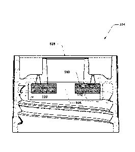
[0027] Figure 5 depicts a section view of an alternate example cap.
[0028] Figure 6 depicts an isometric cutaway view of another example vial with
an
integrated plunger head.
[0029] Figure 6 depicts an isometric view of the example vial of Figure 6 with
a shaft
inserted and the plunger head deployed.
[0030] Figure 6" depicts a section view of the example vial of Figure 6'.
[0031] Figure 7 depicts an isometric cutaway view of another example vial with
an
integrated plunger head.
[0032] Figure 7' depicts an isometric view of the example vial of Figure 7
with a shaft
inserted and the plunger head deployed.
[0033] Figure 8 depicts an isometric cutaway view of another example vial with
an
integrated plunger head.
[0034] Figure 8' depicts an isometric view of the example vial of Figure 8
with a shaft
inserted and the plunger head deployed.
DETAILED DESCRIPTION
10035] Importantly, the present disclosure is neither limited to any single
aspect nor
implementation, nor to any combinations and/or permutations of such aspects
and/or implementations. Moreover, each of the aspects of the present
disclosure,
5
CA 03023119 2018-11-02
WO 2018/128840 PCT/US2017/067833
and/or implementations thereof, may be employed alone or in combination with
one or more of the other aspects and/or implementations thereof. For the sake
of
brevity, many of those permutations and combinations will not be discussed
and/or
illustrated separately herein.
[0036] Provided in examples herein is a sample vial that may be used with
systems
having sampling probes or "sippers" that are insertable into the vial. Such
sample
vials may be used in chemical or biological analysis systems to hold samples
and/or
reagents, and it may, in many systems, be desirable to mix the ingredients of
such
sample vials prior to withdrawing the contents for analysis. Disclosed herein
is a
new type of cap that may be used with sample vials in order to provide a
highly
effective mixing system.
[0037] In general, such caps may include a separable plunger head that is
retained
by features on the cap but that may be released by the cap upon the
application of
sufficient force. The plunger head may have a diameter that is smaller than
the
interior diameter of the container of the sample vial to allow fluid within
the
container to flow past the plunger head as the plunger head is reciprocated
within
the sample vial. Alternatively, the plunger head may have the same diameter as
(or
one slightly larger than) the interior diameter of the container¨however, the
plunger head, in such instances, may also include through-holes, exterior
channels,
.. etc. to allow the fluid to flow past the plunger head as the plunger head
is
reciprocated within the container. The plunger head may be located on the
interior-
facing side of the cap, and the cap may have an opening through which the
shaft of a
sampling probe or sipper may be inserted in order to push on the plunger head
and
provide the force sufficient to release the plunger head from the cap. The
plunger
head may have a shaft-receiving feature that interfaces with the shaft of the
sampling probe such that the plunger head becomes connected to the sampling
probe and moves with the sampling probe within the container once released
from
the cap. Once the plunger head is connected with the sampling probe, the
sampling
probe with attached plunger head may be reciprocated within the interior
volume of
the container, which may act to mix the contents of the container.
6
CA 03023119 2018-11-02
WO 2018/128840 PCT/1JS2017/067833
[0038] Figure 1 depicts an isometric view of an example vial, Figure 1'
depicts a
section view of the example vial of Figure 1, and Figure 1" depicts an
isometric
section view of the example vial of Figure 1. Figure 2 depicts a detail
section view of
the cap of the example vial of Figure 1.
[0039] Depicted in Figures 1-1" are a vial 100 that has a cap 104 and a
container
102; the vial 100 may be sized to fit within a receptacle 142 that holds the
vial 100
during mixing operations. The cap 104 may have a capping surface 106 (see
Figure
2) that generally faces towards the interior of the container 102 and that
acts to wall
off the open end of the container that the cap is fastened to; the cap 104 may
also
have a sidewall or sidewalls 108 that face inwards and extend away from the
capping
surface 106 in directions substantially perpendicular to the capping surface
106 (in
this case, there is a slight taper to the sidewall 108, and "substantially
perpendicular"
in this context may be understood to refer to sidewalls that are within 10
of
perpendicular; the sidewall may also be thought of as extending away from the
capping surface along a direction having a major component 148 that is
perpendicular to the capping surface). In the example implementation, there is
a
single, circular sidewall 108. The cap 104, however, has an opening 114 that
passes
through the capping surface 106 to allow a probe or sipper shaft to be
inserted
through the cap 104 and into the interior of the container 102 without
requiring
removal of the cap 104. In some implementations, the opening 114 may be sealed
with a perforable seal 128, such as a foil induction seal or other membrane,
to
prevent potential leaks or contamination of the fluid within the container
102.
[0040] The cap 104 may have retained within it a plunger head 110. The plunger
head 110 may be retained within the cap 104 by a retaining feature 112. In
this
.. example, the retaining feature 112 consists of an annular wall with an
interior-facing
surface 120 that has one or more ledge surfaces 122 projecting radially
inwards from
it. The ledge surface or surfaces 122 may provide innermost edges 124 that are
slightly smaller, e.g., about 0.2 to about 0.5 mm, than the outermost diameter
of the
plunger head 110, thereby preventing the plunger head 110 from falling out of
the
cap 104. Put another way, the innermost edge or edges 124 may be within a
7
CA 03023119 2018-11-02
WO 2018/128840 PCT/US2017/067833
prismatic volume 146 that is defined by the outermost perimeter of the plunger
head 110 and that extends along the direction 148 that is normal to the
capping
surface 106. However, if sufficient force is applied to the plunger head 110
along a
direction generally perpendicular to the capping surface 106 and towards the
container 102, the plunger head 110 may be forced past the ledge surface 122
and
into the container 102. For example, the plunger head 110 may force the ledge
to
deform and cause the innermost diameter of the ledge surface 122 to expand
and/or
the plunger head 110 may itself compress to reduce the outermost diameter of
the
plunger head 110 in order to allow the plunger head 110 to escape the
retaining
feature 112. In some implementations, the interior-facing surface or surfaces
120
may define an inner perimeter that is larger than the outermost perimeter of
the
plunger head 110, thereby allowing the plunger head 110 to float within the
cap 104
while still being retained by a ledge-type retaining feature 112.
[0041] The plunger head 110 may include a shaft retaining feature 116 that
acts to
receive an insertion portion of a shaft, e.g., of a probe or a sipper. The
shaft
retaining feature 116 may be slightly smaller in size than the outer perimeter
of the
shaft that is intended to be inserted therein, thereby creating a press fit
between the
shaft and the shaft retaining feature 116.
[0042] The cap 104 may be fastened to the container 102 using thread features
126,
although other types of connections may be used as well, such as
friction/press-fit
connections, bayonet-style connections, or barbed, single use connections that
are
tamper-resistant.
[0043] Figure 3 depicts a section view of the example vial of Figure 1 after
being
punctured by a sampling probe, Figure 3' depicts an isometric section view of
the
example vial of Figure 3, Figure 4 depicts a section view of the example vial
of Figure
3 after the sampling probe has been fully inserted into the vial, and Figure
4' depicts
an isometric section view of the example vial of Figure 4. As discussed above,
the
vial 100 may be inserted into a receptacle 142 for mixing operations. A sample
probe with a shaft 118 may then be lowered into the cap 104, e.g., by a shaft
reciprocation system 134. In implementations with a perforable seal 128, the
shaft
8
CA 03023119 2018-11-02
WO 2018/128840 PCT/US2017/067833
118 may be inserted through the perforable seal 128, thereby breaking the
seal. The
shaft 118 may then be inserted further into the cap 104 such that an insertion
portion 130 of the shaft, e.g., the tip, is inserted into the shaft-receiving
feature 116
of the plunger head 110. As discussed earlier, the shaft-receiving feature 116
may
be sized so as to press-fit with the shaft 118. The retaining feature(s) 112
may be
sized such that the amount of force that is required to free the plunger head
110
from the retaining feature(s) 112 is greater than the amount of force required
to
insert the insertion portion 130 into the shaft-receiving feature 116. This
ensures
that the plunger head 110 is not ejected from the retaining feature(s) 112
before the
plunger head 110 is press fit onto the shaft 118. The shaft 118 may also have
a stop
portion 132, e.g., a swaged or brazed ferrule or bushing, that is a larger
diameter
than then shaft-receiving feature. The stop portion 132 may butt up against
the
plunger head 110 when the insertion portion 130 is fully inserted into the
shaft-
receiving feature 116. Once the stop portion 132 is engaged with the plunger
head
110, then generally all of the downward force that is applied to the shaft 118
may be
transferred to the plunger head 110 and used to force the plunger head 110 to
disengage from the retaining feature 112. Once the plunger head 110 is
disengaged
from the retaining feature 112, the shaft reciprocation mechanism 134 may be
used
to move the shaft 118 up and down within the container 102 such that the
plunger
head 110 is reciprocated within the interior 144 of the container 102. Any
fluids that
are present within the interior volume 144 may thus be forced to flow back and
forth
past the plunger head 110, thereby ensuring adequate mixing. Between 4 and 7
reciprocations (up/down motions) was found to provide sufficient mixing in
many
sample test cases.
[0044] Once the contents of the container 102 have been thoroughly mixed by
reciprocating the plunger head within the container 102, the shaft 118 may be
extended such that the insertion portion 130 is located at the bottom of the
container 102. Fluid that has collected at the bottom of the container 102 may
be
drawn up through the shaft 118, e.g., by a pump or other suction-generating
device.
Once sufficient fluid has been withdrawn from the container 102, the shaft 118
may
be withdrawn from the container 102. During such withdrawal, the plunger head
9
110 may contact the retaining feature(s) 112, which may prevent the plunger
head
110 from further movement, thus causing the plunger head 110 to separate from
the
shaft 118 and fall back into the container 102. In some implementations, the
plunger head 110 may be re-captured by the retaining feature 112 or a portion
thereof so that the plunger head 110 still separates from the shaft 118 but
does not
fall back into the container 102.
[0045] The plunger head 110 may be made from a plastic or other polymeric
material, such as a stiff elastomer. This may allow the plunger head 110 to be
somewhat compliant, allowing it to flex and compress as it is freed from the
retaining feature 112, and may also allow the plunger head to easily expand to
accommodate the press fit of the shaft 118.
[0046] Figure 5 depicts a section view of an alternate example cap. In this
view, cap
504's retaining feature 512 has no ledge surface and is instead provided by a
circular
wall with interior-facing surfaces 520 that are sized slightly smaller in
interior
.. diameter than the external diameter of plunger head 510, thereby holding
the
plunger head 510 in place through compression and friction. Cap 504 has a
capping
surface 506. In some embodiments, the opening may be sealed with a perforable
seal 528, such as a foil induction seal or other membrane.
[0047] Figure 6 depicts an isometric cutaway view of another example vial with
an
integrated plunger head. Figure 6' depicts an isometric view of the example
vial of
Figure 6 with a shaft inserted and the plunger head deployed. Figure 6"
depicts a
section view of the sample vial of Figure 6'.
[0048] In Figures 6 through 6", a vial is shown with a container 602 and a cap
604.
The cap 604 has a plunger head 610 that is retained within the cap 604 by a
retaining
feature 612 that has cylindrical interior-facing surfaces that are sized so
that the
plunger head 612 is a light press fit into the retaining feature 612.
Additionally, the
retaining feature 612 may have a circular ridge 654 that narrows the retaining
feature 612 even further. This circular ridge 654 requires that additional
force be
applied to the plunger head 610 in order to break it free from the retaining
feature
3894756
Date Recue/Date Received 2020-04-17
612 beyond the force that is required to break the plunger head 610 free from
the
press fit alone. Thus, the circular ridge 654 retains the plunger head during
insertion
of the insertion portion 630 of the shaft 618, and the shaft 618 then pushes
the
plunger head past the circular ridge 654 when the stop portion 632 of the
shaft 618
butts up against an interior ledge/surface of the shaft-receiving feature in
the
plunger head 610. The plunger head 610 is then reciprocated within the
container
602. When the shaft 618 is removed from the container 602, the plunger head
610
may re-engage with the retaining feature 612 and, in some implementations, may
re-engage with a lower portion 658 of the retaining feature 612, which is
separated
from an upper portion 656 of the retaining feature 612 by the circular ridge
654. The
retaining feature 612 may thus re-capture the plunger head 610 upon withdrawal
of
the shaft 618. In some embodiments, the opening may be sealed with a
perforable
seal 628, such as a foil induction seal or other membrane.
[0049] In this implementation, the plunger head 610 has a plurality of grooves
or
channels 650 around the exterior perimeter to allow for enhanced fluid flow
past the
plunger head 610 during mixing.
[0050] Figure 7 depicts an isometric cutaway view of another example vial with
an
integrated plunger head. Figure 7' depicts an isometric view of the example
vial of
Figure 7 with a shaft inserted and the plunger head deployed. In Figures 7 and
7', a
vial very similar to that shown in Figures 6 through 6" is shown, except that
the
plunger head 710 has no grooves in it, and the retaining feature 712 does not
have
the circular ridge and instead relies on a tighter press fit with the plunger
head 710.
[0051] Figure 8 depicts an isometric cutaway view of another example vial with
an
integrated plunger head. Figure 8' depicts an isometric view of the example
vial of
Figure 8 with a shaft inserted and the plunger head deployed. In Figures 8 and
8',
the plunger head 810 has a pattern of through-holes 852 that allow for fluid
to flow
through the plunger head 810 during reciprocation of the plunger head 810. The
cap
804 also has a retaining feature 812 that is similar to that shown in Figure
7.
Otherwise, the vial shown in Figures 8 and 8' is similar to the vial shown in
Figures 1
through 4.
11
3894756
Date Recue/Date Received 2020-04-17
[0052] The terms "substantially" and "about" used throughout this disclosure,
including the claims, are used to describe and account for small fluctuations,
such as
due to variations in processing. For example, unless otherwise specified
herein in a
particular context, they can refer to less than or equal to 5%, of the
specified value
or value equivalent to the specified relationship, such as less than or equal
to 2%,
such as less than or equal to 1%, such as less than or equal to 0.5%, such
as less
than or equal to 0.2%, such as less than or equal to 0.1%, such as less than
or
equal to 0.05%. For example, "substantially perpendicular" may be used to
refer to
a geometric relationship in which the angle between two surfaces is within 5%
(or,
.. alternatively, one of the other bounding ranges listed above) of 90 .
[0053] The use, if any, of ordinal indicators, e.g., (a), (b), (c)... or the
like, in this
disclosure and claims is to be understood as not conveying any particular
order or
sequence, except to the extent that such an order or sequence is explicitly
indicated.
For example, if there are three steps labeled (i), (ii), and (iii), it is to
be understood
that these steps may be performed in any order (or even concurrently, if not
otherwise contraindicated) unless indicated otherwise. For example, if step
(ii)
involves the handling of an element that is created in step (i), then step
(ii) may be
viewed as happening at some point after step (i). Similarly, if step (i)
involves the
handling of an element that is created in step (ii), the reverse is to be
understood.
.. [0054] It is also to be understood that the use of "to," e.g., "with which
the cap is to
interface," may be replaceable with language such as "configured to," e.g.,
"with
which the cap is configured to interface ", or the like.
[0055] It should be appreciated that all combinations of the foregoing
concepts
(provided such concepts are not mutually inconsistent) are contemplated as
being
.. part of the inventive subject matter disclosed herein. In particular, all
combinations
of claimed subject matter appearing at the end of this disclosure are
contemplated
as being part of the inventive subject matter disclosed herein. For the sake
of
brevity, many of those permutations and combinations will not be discussed
and/or
illustrated separately herein.
12
3894756
Date Recue/Date Received 2020-04-17