Note : Les descriptions sont présentées dans la langue officielle dans laquelle elles ont été soumises.
CA 03023882 2018-11-09
A SENSING SYSTEM WITH DIFFERENT UPPER LAYERS
Relevant Technical Field
The present invention relates to sensing systems that are used especially in
robotic systems.
Background Art
In order to explore those areas which may be dangerous for human (for example,
different
planets, underground tunnels or caves), exploration robots are used.
Exploration robots
comprise various sensors for detecting objects in the area they are sent and
for identifying
the characteristics of the said objects. One of the sensors used in the said
exploration robots
is tactile sensors. By means of the tactile sensors, presence of certain
objects and some
physical features thereof such as pressure can be detected.
The conventional tactile sensors comprise a light source positioned under an
elastic surface
and a light sensing element for sensing the amount of the light reflected from
the said
surface, as disclosed in US2010155579A1. In such tactile sensors, when a force
is applied
on the elastic surface, the said surface approaches to the light source and
the light sensing
element. As a result of such approach, the amount of light incident on the
light sensing
element increases. The amount of light sensed by the light sensing element and
resilience
properties of the surface are used to calculate the amount of force applied to
the surface.
However, in this embodiment, the number of light sources that may be
positioned under the
unit surface and of the light sensing elements are limited, and it is
cumbersome to process
data received from a high number of light sensing elements.
Said problems are solved by a module disclosed in W02014011126A1. The said
module
comprises an elastic material, which is covered with a layer providing light
reflection; a
CMOS or CCD image sensor; at least one light source; a plurality of first
fiber optic cables, a
tips of which are separated from surrounding environment via said layer by
being located
under the layer and other tips of which are in connection with said light
source, wherein said
first fiber optic cables carry light beams from the light source to said
layer; a plurality of
second fiber optic cables, a tips of which are separated from surrounding
environment via
1
CA 03023882 2018-11-09
said layer by being located under the layer and being directed towards the
layer and other
tips of which are in connection with said image sensor so that each second
fiber optic cable
is paired with one pixel of the image sensor, wherein light beams reflected
from the layer are
transferred to the image sensor by said second fiber optic cables; a processor
which
calculates every individual force applied to the layer according to light
intensity changes of
each pixel connected with a second fiber cable, of a photo frame generated by
the image
sensor in response to the displacement of the layer by using image processing
techniques.
In the module disclosed in W02014011126A1, when the elastic material contacts
to an
object, a deformation is generated in the elastic material and the said layer
(e.g.
displacement of the layer towards the fiber optic cables). As a result of such
displacement,
the amount of light reflected from the layer to the fiber optic cable is
changed. Said change in
the amount of light is detected as a color change in the photo frame generated
in the image
sensor. The processor applies image processing techniques to the said photo
frame so as to
measure color changes of the photo, and thus the amount of displacement of the
layer.
Based on the amount of displacement calculated, the force applied on the
elastic material is
also calculated. However, due to the fact that in the said embodiment
detection is only
performed based on the level of light, an improvement is needed.
Another patent document US4547668A discloses a two-dimensional pressure
sensor. Said
pressure sensor comprises a light source; a matrix of light transmitting fiber
endings
comprising a plurality of fibers for transmitting said light from said light
source and a plurality
of fibers for receiving reflected light; a transmitting fiber sub-array
comprising endings of said
transmitting fibers located a distance from said matrix of light transmitting
fiber endings, said
endings located to receive light from said light source; a receiving fiber sub-
array, comprising
endings of said receiving fibers located a distance from said matrix of light
transmitting fiber
endings; a retro-reflective material located a distance above said matrix; a
semi-transparent
deformable medium located between said matrix and said retro-reflective
material, said semi-
transparent deformable medium supporting said retro-reflective material; a
flexible
membrane located adjacent said retro-reflective material side farthest from
said matrix; and
means located adjacent said receiving fiber sub-array, for detecting said
reflected light
transmitted by said light fibers from said matrix to said receiving fiber sub-
array.
2
CA 03023882 2018-11-09
Another patent document W02005029028A1 discloses an optical tactile sensor.
Said optical
tactile sensor comprises a sensing part comprising a transparent elastic body
and a plurality
of marker groups provided in said body, each marker group being comprised of a
number of
colored markers, with markers constituting different marker groups having
different colors for
each group, said elastic body having an arbitrary curved surface; a
photographing device for
taking an image of behavior of colored markers when said curved surface of
elastic body is
contacted by an object to obtain image information of markers, and a force
vector distribution
reconstructing device including a transfer function by which a force vector
applied to the
surface is reconstructed from information as to the behavior of markers that
is obtained from
the image information of markers, and said force vector distribution
reconstructing device
reconstructing forces applied to said surface from said information as to the
behavior of
markers by using the transfer function.
Brief Description of the Invention
The sensing system according to the present invention which detects touch
comprises at
least an intermediate layer; at least a upper layer located on the
intermediate layer; at least
one light source located under the intermediate layer; at least one image
sensor located
under the intermediate layer; at least a first fiber optic bundle comprising a
plurality of fiber
optic cables positioned such that a tips of which is facing to the light
source and other tips of
which is facing to the said intermediate layer, and transmitting the light
obtained from the
light source to the upper layer located on the intermediate layer; at least a
second fiber optic
bundle comprising a plurality of fiber optic cables, a tips of which is paired
with at least one
pixel of the image sensor and other tips of which is positioned facing to the
intermediate
layer, and transmitting the image of the upper layer located on the
intermediate layer to the
image sensor; at least one control unit which analyzes the image captured by
the image
sensor using image processing techniques so as to calculate a force applied on
the
intermediate layer; and at least a data link for data communication between
the image sensor
and the control unit.
In the sensing system according to the present invention, the light beams
received from the
light source pass through the intermediate layer onto the upper layer via the
first fiber optic
bundle. An image of the upper layer is transmitted to the image sensor via the
second fiber
3
CA 03023882 2018-11-09
optic bundle. Here, when a force is applied through the upper layer onto the
intermediate
layer, an image frame of a form (pattern) change, a color change or a
brightness change of
the upper layer captured by the image sensor is analyzed by the control unit
using image
processing techniques so that the force applied through the upper layer onto
the intermediate
layer may be calculated.
Object of the Invention
An object of the present invention is to provide a sensing system suitable for
use in robotic
systems.
Another object of the present invention is to provide a sensing system capable
of sensing
touch.
Another object of the present invention is to provide a sensing system with
reduced power
consumption.
Another object of the present invention is to provide a sensing system wherein
it is detected
whether it is subjected to a certain force.
Another object of the present invention is to provide a sensing system wherein
application
point and area of the force applied is detected.
Another object of the present invention is to provide a sensing system wherein
the pressure
applied is detected.
Yet another object of the present invention is to provide a sensing system
capable of
detecting the forces applied in vertical direction to the sensor as well as
the combined forces.
4
CA 03023882 2018-11-09
Description of the Drawings
Illustrative embodiments of the sensing system according to the present
invention are
illustrated in the enclosed drawings, in which:
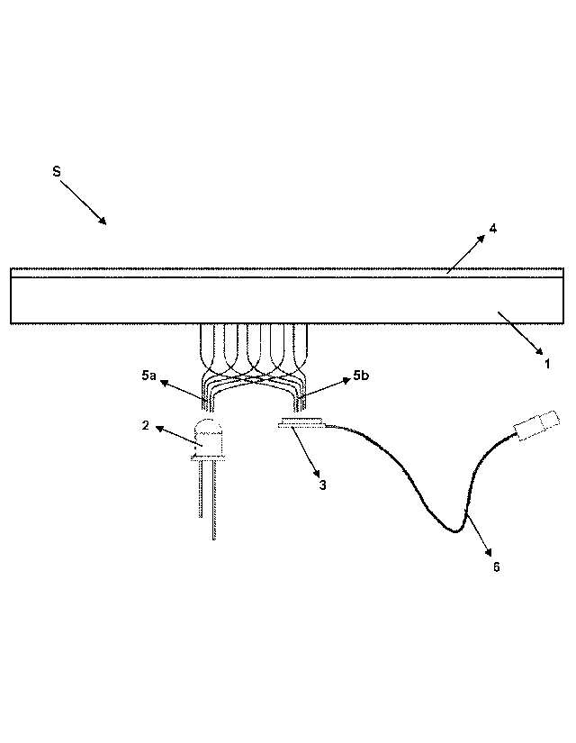
Figure 1 is a side view of the sensing system.
Figure 2 is a perspective view of an exemplary embodiment of the sensing
system.
Figure 3 is a perspective view of an exemplary embodiment of the sensing
system as
used.
Figure 4 is a side view of another exemplary embodiment of the sensing system.
Figure 5 is a side view of another exemplary embodiment of the sensing system
as
used.
Figure 6 is a side view of another exemplary embodiment of the sensing system.
All the parts illustrated in the drawings are individually assigned a
reference numeral and the
corresponding terms of these numbers are listed as follows:
Sensing system (S)
Intermediate layer (1)
Light source (2)
Image sensor (3)
Upper layer (4)
First fiber optic bundle (5a)
Second fiber optic bundle (5b)
Data link (6)
Pattern (7)
Outer layer (8)
Elastic element (9)
Obstacle (10)
Distance element (11)
5
CA 03023882 2018-11-09
Description of the Invention
With the advanced robot technology, senses such as seeing, hearing, touching
can be
detected by sensor systems. Particularly, in exploration robots used to
explore those areas
that are dangerous for humans or not possible for humankind to arrive, the
characteristics of
the areas that are being explored can be detected accurately by means of the
said sensor
systems. Therefore, with the present invention, there is provided a sensing
system capable
of sensing touch.
The sensing system (S) according to the present invention, as illustrated in
figures 1-6,
comprises at least an intermediate layer (1); at least a upper layer (4)
located on the
intermediate layer (1); at least one light source (2) located under the
intermediate layer (1)
(distant to the upper layer (4)); at least one image sensor (3) (i.e. a CCD,
CMOS sensor etc.)
located under the intermediate layer (1) (distant to the upper layer (4)); at
least a first fiber
optic bundle (5a) comprising a plurality of fiber optic cables positioned such
that a tips of
which is facing to the light source (2) and other tips of which is facing to
the said intermediate
layer (1), and transmitting the light obtained from the light source (2) to
the upper layer (4)
located on the intermediate layer (1); at least a second fiber optic bundle
(5b) comprising a
plurality of fiber optic cables, a tips of which is paired with at least one
pixel of the image
sensor (3) and other tips of which is positioned facing to the said
intermediate layer (1), and
transmitting the image of the upper layer (4) located on the intermediate
layer (1) to the
image sensor (3); at least one control unit (not shown) which analyzes the
image captured by
the image sensor (3) using image processing techniques so as to calculate a
force applied
on the intermediate layer (1); and at least a data link (6) for data
communication between the
image sensor (3) and the control unit. Said data link (6) may be a wired
connection or a
wireless connection.
In a preferred embodiment of the invention, said upper layer (4) comprises at
least a pattern
(7), as shown in figures 2 and 3. The pattern (7) preferably having a squared,
chess board
shape deforms towards the intermediate layer (1), when exposed to a force, as
shown in
figure 3. An image frame of the upper layer (4) captured by the image sensor
(3) is
processed in the said control unit in order to determine in which area the
pattern (7) has
6
CA 03023882 2018-11-09
deformed and to what extent and how, and accordingly the force and pressure
applied on the
intermediate layer (1) is calculated.
In another preferred embodiment of the invention, said upper layer (4)
comprises a material
that changes color with force. In an illustrative embodiment, the upper layer
(4) comprises a
polarized film. If a force is applied on the polarized film, color changes are
observed in the
film based on the intensity of the force applied. Since the image frame of the
upper layer (4)
captured by the image sensor (3) is analyzed by the control unit using image
processing
techniques, the extent of color change in the polarized film is detected. As
the said color
change and area of color change is associated with the force applied on the
upper layer (4),
the extent of force and pressure applied through the upper layer (4) onto the
intermediate
layer (1) is also calculated.
In another preferred embodiment of the invention, the upper layer (4)
comprises a
piezochromic material. Piezochromic materials change color with pressure. Said
color
change varies depending on the pressure applied. In this embodiment, since the
image
frame of the upper layer (4) captured by the image sensor (3) is analyzed by
the control unit
using image processing techniques, color change in the piezochromic material,
area of color
change and thus the extent of the force and pressure applied through the upper
layer (4)
onto the intermediate layer (1) are calculated. Piezochromic materials may be
reversible
(which returns to its original color when the force applied thereon is
removed) or irreversible
(which does not return its original color when the force applied thereon is
removed). In a
preferred embodiment of the invention, the piezochromic material used in the
sensing system
(S) is reversible. Thus, when the force applied on the intermediate layer (1)
is removed,
piezochromic material returns to its original color and when a different force
is applied on the
intermediate layer (1), the newly-applied force is also detected. In an
alternative
embodiment, said upper layer (4) comprises a first layer positioned at its
side close to the
surrounding environment and preferably containing a reversible piezochromic
material (or
any one of other types of top surfaces), and a second layer positioned at its
side distant to
the surrounding environment and containing irreversible piezochromic material.
In this
embodiment, when a force is externally applied on the intermediate layer (1),
a force and
pressure is applied on the second layer as well. However, when a force higher
than the
envisaged force is applied on the intermediate layer (1), a force higher than
the threshold
7
CA 03023882 2018-11-09
value is imposed on the second layer and the color of the second layer
permanently changes
due to the irreversible piezochromic material thereof. Thus, it is detected
whether a force
higher than the envisaged force is applied on the intermediate layer (1) or
not, as well as the
magnitude of the force applied based on the color change of the second layer.
In another preferred embodiment of the invention, the upper layer (4)
comprises at least an
outer layer (8) which is elastic and light-proof, at least an elastic element
(9) positioned under
the outer layer (8) and which is transparent and preferably in the form of a
gel, and a plurality
of (for example, at least in two rows) obstacles (10) positioned in the
elastic element (9) and
which are in the form of a light-proof particle such that its color is
different from the outer
layer (8), as shown in figures 4 and 5. As shown in figure 5, when a force is
applied through
the upper layer (4) onto the intermediate layer (1), said outer layer (8)
pushes the obstacles
(10) to right and left sides and approaches to the intermediate layer (1). As
a result of this
movement, color changes are seen in the image frame of the upper layer (4)
captured by the
image sensor (3). By analyzing the said image frame by the control unit using
image
processing techniques, the extent of the color change is determined. Thus, the
amount of
force applied through the upper layer (4) onto the intermediate layer (1) is
calculated.
In another preferred embodiment of the invention, the said upper layer (4)
comprises a
phosphor and/or any other material that stores a part of the light in itself
but proceeds to emit
light when the light coming from the light source is cut off. In this
embodiment, the said light
source (2) is activated at certain intervals in order to increase energy of
the phosphor and/or
similar material. Thus, even if the light source (2) is switched off, phosphor
and/or similar
material emits light for a certain period of time. In this embodiment, when a
force is applied
through the upper layer (4) onto the intermediate layer (1), the brightness of
a section of the
image frame of the upper layer (4) captured by the image sensor (3) which is
subjected to
force is higher than those sections which are not subjected to force. In the
said image frame,
brightness of different pixels is compared so that the force applied through
the upper layer
(4) on the intermediate layer (1) may be calculated.
In an alternative embodiment of the invention, said upper layer (4) partially
transmits light (for
example, a mirror film or a fine porous structure like a veil). As known, such
structures
normally transmit light but if an opaque object blocking transmission of light
is placed behind
8
CA 03023882 2018-11-09
same, it reflects light back. In this embodiment, light beams received from
the light source
(2), which are transmitted through the intermediate layer (1) onto the upper
layer (4) via the
first fiber optic bundle (5a), are normally transmitted to the surrounding
environment (and an
image of the surrounding environment is present in the image captured by the
image sensor
(3)). However, if an object is placed on the intermediate layer (1), light
beams pass through
the upper layer (4) and impinge onto the object and are reflected back from
the object. An
image of the said object is also present in the image frame captured by the
image sensor (3).
The image frame captured by the image sensor (3) is analyzed by the control
unit using
image processing techniques so that the force applied through the upper layer
(4) onto the
.. intermediate layer (1) may be calculated.
In another alternative embodiment of the invention, the first fiber optic
bundle (5a), and/or the
second fiber optic bundle (5b) are multi-piece bundles. In this embodiment,
the first fiber
optic bundle (5a) and/or the second fiber optic bundle (5b) comprises a first
section including
a plurality of fiber optic cables; a second section including a plurality of
fiber optic cables; and
a carrier fiber optic cable, to end of which is connected a tip of each fiber
optic cables in the
said first section and to another end of which is connected a tip of each
fiber optic cable in
the said second section, whose diameter is larger than that of the fiber optic
cables in the
first section and the second section, and which transmits the lights carried
by the fiber optic
cables in the first section to the fiber optic cables in the second section
and the lights carried
by the fiber optic cables in the second section to the fiber optic cables in
the first section. In
this way, in the embodiments wherein the length of the fiber optic cables must
be long, it will
be sufficient that one or a limited number of fiber optic cables (carrier
fiber) is long, instead of
a high number of fiber optic cables. In another embodiment of the carrier
fiber, the diameter
.. of the said carrier fiber optic cable is lower than that of the first
section and the second
section. In this embodiment, in order to have an exact pairing of each fiber
optic cable in the
first section with each fiber optic cable in the second section (i.e. to
ensure that the light
beams coming from different fiber optic cables do not intervene with each
other), the first
optic bundle (5a) and/or the second fiber optic bundle (5b) also comprise at
least two optic
elements, each interposed between the carrier fiber optic cable and the first
section, and
between the carrier fiber optic cable and the second section. The said optic
elements prevent
the light beams flowing through the carrier fiber optic cable from intervening
with each other.
9
CA 03023882 2018-11-09
In an alternative embodiment of the invention shown in figure 6, the sensing
system
comprises at least two distance elements (11), positioned between the said
upper layer (4)
and the intermediate layer (1), and which maintain the upper layer (4) and the
intermediate
layer (1) spaced from each other. In this embodiment, said upper layer (4) may
either be
elastic, or may be rigid.
In the sensing system (S) according to the present invention, light beams
received from the
light source (2) are passed through the intermediate layer (1) and onto the
upper layer (4) via
the first fiber optic bundle (5a). An image of the upper layer (4) is
transmitted to the image
sensor by means of the second fiber optic bundle (5b). Here, when a force is
applied through
the upper layer (4) onto the intermediate layer (1), an image frame of the
form (and/or pattern
(7)) change, color change or brightness change of the top surface (4) captured
by the image
sensor (3) is analyzed by the control unit using image processing techniques,
so that the
force applied through the upper layer (4) onto the intermediate layer (1) may
be calculated.
Furthermore, thanks to the displacement area represented by the area of color
change in the
image obtained, the pressure applied in any direction (for example,
transversal angles) is
calculated. Furthermore, with the detection of a change in a pattern (7) of
the upper layer (4),
the forces applied on the upper layer (4) from different angles (e.g. right
angles) as well as
their direction may also be detected.