Note : Les descriptions sont présentées dans la langue officielle dans laquelle elles ont été soumises.
SNOW VEHICLE
CROSS-REFERENCE TO RELATED TO APPLICATION(S)
[0001] This application claims benefit of US Provisional Application
No.
62/586,559, filed on November 15, 2017, and which application is incorporated
herein
by reference. A claim of priority is made.
BACKGROUND
[0002] In addition to traditional snowmobiles, an alternative snow
vehicle is the
snow bike or snow cycle. These vehicles are generally smaller and lighter than
snowmobiles. Snow cycle designs are typically based upon off-road motorcycles
with
the front wheel replaced by a ski and the rear wheel replaced by an endless
loop traction
belt, commonly called a track. Snow bikes typically have a single steering ski
and a
relatively narrow track located behind and in line with the single ski.
SUMMARY
[0003] Embodiments of the present disclosure describe a snow
vehicle,
comprising an engine mounted on a frame, a drive track, a drive train
operatively
interconnecting the engine with the drive track for delivering propulsive
power to the
drive track, and exhaust system. The exhaust system is positioned within an
interior of
the frame of the vehicle.
[0004] Embodiments relate to a snow vehicle, comprising an engine
mounted on a
frame, a drive track, a drive train operatively interconnecting the engine
with the drive
track for delivering propulsive power to the drive track, and an engine air
intake system,
positioned above the engine. The air intake system includes a rearward
positioned air
intake port.
[0005] Embodiments also relate to a snow vehicle, comprising an
engine mounted
on a frame, a drive track, a drive train operatively interconnecting the
engine with the
drive track for delivering propulsive power to the drive track, an engine air
intake
system positioned above the engine, and an exhaust system positioned within an
interior
of the frame of the vehicle. The air intake system includes a reatwardly
facing air intake
port; and wherein the drive train includes a CVT.
1
CA 3024226 2018-11-15
BRIEF DESCRIPTION OF DRAWINGS
[0006] This written disclosure describes illustrative embodiments
that are non-
limiting and non-exhaustive. Reference is made to illustrative embodiments
that are
depicted in the figures, in which:
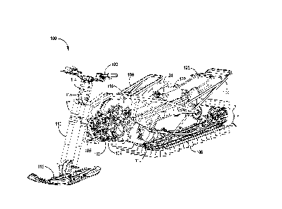
[0007] FIG. 1 illustrates a perspective view 100 of a snow vehicle,
according to
some embodiments.
[0008] FIG. 2 illustrates a perspective view 100 of a snow vehicle
with air intake
system, according to some embodiments.
[0009] FIG. 3 illustrates a partial top-down view 300 of a snow
vehicle with air
intake system (engine removed), according to some embodiments.
[0010] FIG. 4 illustrates a partial top-down view 300 of a snow
vehicle with air
intake system, according to some embodiments.
[0011] FIGS. 5A-D illustrate perspective views 500 of an air intake
system,
according to some embodiments.
[0012] FIG. 6 illustrates a partial side view 600 of a snow vehicle
with air intake
system, according to some embodiments.
[0013] FIG. 7 illustrates a side view 700 of a snow vehicle,
according to some
embodiments.
[0014] FIG. 8 illustrates a perspective view 100 of a snow vehicle
with engine
removed, according to some embodiments.
[0015] FIG. 9 illustrates a side view 700 of a snow vehicle with
engine removed,
according to some embodiments.
[0016] FIG. 10 illustrates a top-down view 1000 of a snow vehicle
with cooling
system, according to some embodiments.
[0017] FIGS. 11A-B illustrate perspective views 1100 of power train
components,
according to some embodiments.
[0018] FIGS. 12A-D illustrate perspective views 1200 of power train
components, according to some embodiments.
[0019] FIG. 13 illustrates a side view 13 of a continuously variable
transmission
(CVT) housing with air handling components and drop box, according to some
embodiments.
[0020] FIG. 14 illustrates a perspective view 1400 of a cooling
system, according
to some embodiments.
2
CA 3024226 2018-11-15
[0021] FIG. 15 illustrates a side view 700 of a snow vehicle with
engine removed
and with a cooling system, according to some embodiments.
[0022] FIG. 16 illustrates a top-down view 1000 of a snow vehicle
tunnel shroud,
according to some embodiments.
[0023] FIG. 17 illustrates a perspective view 100 of a snow vehicle
with two- ski
configuration, according to some embodiments.
[0024] FIG. 18 illustrates a side view 700 of a snow vehicle with two-
ski
configuration, according to some embodiments.
[0025] FIG. 19 illustrates a top-down view 1000 of a snow vehicle
with two-ski
configuration, according to some embodiments.
[0026] FIGS. 20A-C illustrate user or rider positioning in a dirt
bike and in a
snow vehicle, according to some embodiments.
DETAILED DESCRIPTION
[0027] Snow vehicles, such as snow bikes, are often created as
modifications or
kits of off-road motorcycles or dirt bikes. The front wheel is temporarily
replaced by a
ski and the rear wheel by a power track for gripping snow and ice. Such
vehicles exceed
noise and safety regulations and are therefore often restricted to use on
closed courses.
In snow vehicle applications, reducing the weight of individual components and
overall
vehicle weight, without sacrificing durability, function or utility, is an
ongoing goal in
product design. A lighter vehicle can increase performance and handling, among
other
characteristics. Embodiments of the present disclosure describe a purpose-
built snow
vehicle with numerous advantages over current snow vehicles and snow bike
kits.
Embodiments herein describe a snow vehicle utilizing a continuously variable
transmission (CVT) with an air handling system. The snow vehicle includes an
exhaust
system positioned entirely within the chassis and tunnel of the vehicle, to
prevent any
contact with a user or their clothing. The snow vehicle further includes a
lower center of
gravity in the positioning of the vehicle components within the purpose-built
frame. The
engine is positioned lower and forward and additional weight, such as one or
more gas
tanks are further positioned to create the optimal center of gravity for
handling and
balance.
[0028] Embodiments herein describe a dropped fork component that
creates a
lower weight of the vehicle and additional adjustment of the handlebars. An
engine air
3
CA 3024226 2018-11-15
handling system provides a rear facing air intake for the engine. The purpose-
built
chassis or frame allows for greater space utilization and a lower center of
gravity of the
vehicle.
[0029] Referring to FIG. 1, a perspective view 100 of a snow vehicle
is shown,
according to some embodiments. A chassis or frame 104 supports an engine 116,
drive
train components, a drive track 106, handlebars 102 and one or more skis 112.
The
chassis includes a seat frame 108, lower front frame component 105, and
integrated
bumper 109. Exhaust system 118 connects to muffler 120. The chassis 104
connects to a
fork 110, in contact with the one or more skis 112. A drop fork component 114
connects
the fork 110 and handlebars 102. Fuel tank 124 is positioned beneath the
exhaust system
118 and seat frame 108. Tunnel shroud 122 is positioned in contact with the
chassis 104
and above the drive track 106. The track width can be about 10 inches to about
12
inches, about 12 inches to about 13 inches, about 12.5 inches, about 13.5
inches, or
about 14 inches wide. A foot peg attachment 119 can be positioned near an
exterior
surface. Examples of drive track 106 and other embodiments can be found in co-
owned
U.S. Patent No. 9,321,509, filed on December 17, 2013 with first named
inventor
Andrew Beavis and entitled "Snowmobile Skid Frame Assembly", the contents of
which are incorporated herein by reference.
[0030] In some embodiments, the exhaust system 118 is positioned
completely
within the tunnel and frame 104 of the vehicle. By rotating the position of
the engine
116 one hundred eighty degrees from a typical snowmobile or motorcycle
configuration, the exhaust port faces a rearward direction. The exhaust system
118 can
then be contained in a substantially linear configuration towards the rear of
the vehicle
and into a muffler 120. The muffler 120 can also be contained within an
interior of the
frame 104. The exhaust then exits the rear of the vehicle. By positioning the
exhaust
system 118 completely within the frame 104 and tunnel of the vehicle, a user
is
protected from incidental contact on the hot surface of the exhaust system
118. A partial
top-down view of a snow vehicle is shown in FIG. 3, in which exhaust system
118 runs
within the width of the frame 104.
[0031] FIG. 2 additionally shows engine air intake system 202,
according to some
embodiments. The air intake system 202 is positioned above the motor and can
be
attached to frame 104 or integrated with the frame 104. Shown in FIGS. 3-4 in
a partial
top-down view 300, the air handling system 202 encloses the frame 104 as the
tube
4
CA 3024226 2018-11-15
chassis runs through the box and supports its efficient placement and space
utilization.
The air handling system 202 can alternatively be positioned under the frame
104.
[0032] Referring to FIGS. 5A-D, perspective views 500 of the air
intake system
202 components are shown, according to some embodiments. The air box 206
collects
and funnels air as the vehicle moves. The size and position of the air box
allows for a
sufficient volume of air to be collected and move through the system 202 to
the engine.
Once collected in box 202, the air then travels through channel component 204
to the
engine 116 (see view 600 of FIG. 6). Frame channels 208 can be positioned or
formed
on an interior or exterior surface for attachment or integration with the
frame 104.
[0033] Referring to FIG. 7, a side view 700 of a snow vehicle is
shown, according
to some embodiments. The frame 104 can be comprised of a tube chassis that
maximizes the position of vehicle components for space utilization and weight
reduction. As the snow vehicle is not a kit for motorcycles, the engine 116
can be
positioned much lower and forward as any consideration for the position of a
wheel is
not needed. The lower front frame component 105 can be much closer to fork 110
than
in traditional snow bike configurations. A traditional motorcycle user or
rider posture is
show in FIG. 20A. The ergonomic position El is shown between foot peg, seat
and
handlebars. The angle Al may be between about 27-30 degrees. D1 distance is
about 29
inches in this example. D2 is about 48 inches and D3 about 3.2 inches. In one
embodiment of the snow vehicle of the present disclosure (see FIG. 20B), a
similar
ergonomic position El is achieved. Hence, the rider or user is positioned in a
similar
manner with a user of a dirt bike. This differentiates from the position of a
traditional
snowmobile. In FIG. 20B, angle Al can be about 24 to about 30 degrees, about
26 to
about 28 degrees, or about 26.5 to about 27.5 degrees. D1 distance can be
about 65
inches to about 100 inches. D1 can be about 75 inches to about 90 inches, or
about 80
inches to about 90 inches for example. D6 can be about 20 inches to about 30
inches,
about 22 inches to about 28 inches, or about 24 to about 26 inches. D4 can be
about 15
inches to about 24 inches, about 17 inches to about 22 inches, or about 18 to
about 20
inches. D5 can be about 28 inches to about 42 inches, about 32 inches to about
38
inches or about 34 inches to about 36 inches. D7 measures the distance between
foot
peg and track/drive shaft. Embodiments of the present invention allow for a
smaller
distance between the two components, as the engine 116 is positioned more
forward.
The track/drive shaft can even be positioned more forward than the foot peg.
In
CA 3024226 2018-11-15
motorcycles and snow kits of motorcycles, the track/drive shaft is typically
about 6 to
about 8 inches behind the foot peg (see D7 of FIG. 20C.). In FIG. 20B, the
distance
D7 can be about zero inches to about 1 inch positive (foot peg ahead of the
drive shaft),
or about zero inches to about 1 inch negative (drive shaft ahead of the foot
peg), about 2
inches positive to about 2 inches negative, about 3 inches positive to about 3
inches
negative, or about 4 inches positive to about 4 inches negative.
[0034] Additionally, the frame 104 includes integrated or attached
bumper 109. If
attached, the bumper 109 can be bolted, welded, or otherwise fastened. If
integrated, the
bumper 109 can be of a continuous construction with the frame 104. The bumper
109
can connect to the shroud 122 or be separated from shroud 122. The bumper 109
can
optionally support the shroud 122 at one or more connection points. As the
bumper 109
is part of frame 104 or connected to frame 104, the need for a structural
tunnel shroud is
removed as the bumper does not need to connect to the tunnel shroud. Current
shroud
122 can be made of plastic or lightweight aluminum to further reduce weight of
the
vehicle. The placement of the engine 116 in a forward and lower configuration
advantageously moves the center of gravity of the vehicle in a lower position.
The
position of the one or more fuel tanks 124 further supports the lower center
of gravity.
[0035] Because the frame 104 is purpose-built to for this vehicle,
the size and
length of the fork 110 can be reduced. The frame 104 can connect with fork 110
at a
lower position. The connection between frame 104 and fork 110 can be gusset
bracket
117. The gusset bracket 117 can transfer and distribute load throughout the
frame 104.
A drop fork component 114 can then be utilized to connect the fork 110 and
handlebars
102. The drop fork component 114 is lighter than any corresponding length of
fork 110
and can further be utilized for fore and aft handlebar adjustment and
rotational
adjustment for the user. The drop fork component 114 can include support
components
115, such as a cross brace. The drop fork component 114 can be manufactured of
light
weight, but durable materials, such as aluminum for example. The length of the
drop
fork component 114 can be about 8 inches, about 10 inches, or about 12 inches.
The
length of the drop fork component 114 can be about 6 inches to about 12
inches. The
fork 110 can also include suspension components, such as dampeners, springs,
coils,
etc. The front suspension can be telescoping compression dampening component
or
rebound dampening component, for example.
6
CA 3024226 2018-11-15
[0036] Referring to FIG. 8, a perspective view 100 of a snow vehicle
with engine
116 removed and with cooling system 800 is shown, according to some
embodiments.
With the engine 116 removed from view, the cooling system 800 can be seen. The
cooling lines 802 connect to the engine 116, and a pump (not shown) moves
coolant to
heat exchanger 1002 (see view 1400 of FIG. 14). The tunnel shroud 122 (see top
view
1000 of FIG. 16) covers the heat exchanger 1002 (see view 700 of FIG. 15 and
top
view 1000 of FIG. 10) and deflects snow onto the exchanger 1002 to assist in
cooling
the liquid coolant (see view 700 of FIG. 9). As discussed above, the tunnel
shroud 122
can be manufactured of light weight materials, such as plastic or aluminum as
the need
for structural support has been removed by integrating such function into
frame 104.
The shroud 122 can be vacuum formed, molded, or shaped into various shapes or
configurations for snow deflection functionality and aesthetic considerations.
[0037] Referring to FIGS. 11A-B, 12A-D perspective views 1100, 1200
of power
train components are shown, according to some embodiments. The drive train of
the
snow vehicle includes a continuously variable transmission (CVT), for
transferring
power from the engine 116 to the drive track 106. The use of an automatic
transmission
makes for a smoother user experience and handling as compared to manual
transmission. An engine 116 converts chemical energy to mechanical energy via
a
rotating input shaft in contact with a transmission or drive train, such as a
CVT. The
CVT housing 1112 includes a rotatable drive (or primary) clutch connected to
the input
shaft. The CVT also includes a rotatable driven (or secondary) clutch
connected to an
output shaft or jack shaft 1108, the driven clutch having a laterally
stationary sheave and
a laterally movable sheave that is normally biased toward the stationary
sheave. An
endless flexible drive belt is disposed about the drive and driven clutches.
Typically, the
CVT transmission is connected to the output shaft 1108 of the vehicle's
engine, the
transmission providing continuously variable gear reduction from the
relatively higher
rotation speed of the engine to the relatively lower rotation speed of the
vehicle drive
axle. The CVT 1112 is used in conjunction with or integrated with a gear or
drop box
1302 (see view 1300 of FIG. 13), for correcting the rotation of the output
shaft 1108
due to the position of the engine. The drop box 1302 can include two or more
gears
1304. The CVT housing 1112 with drop box 1302 is connected to the jack shaft
1108.
Power is transferred via a belt 1110 from the jack shaft 1108 to driveshaft
1106,
connected by suitable linkages (sprockets 1116, for example) to the drive
track 106.
7
CA 3024226 2018-11-15
[0038] The endless, flexible, generally V-shaped drive belt is
disposed about the
clutches within housing 1112. Each of the clutches has a pair of complementary
sheaves, one of the sheaves being laterally movable with respect to the other.
The
effective gear ratio of the transmission is determined by the positions of the
movable
sheaves in each of the clutches. The secondary driven clutch has its sheaves
normally
biased together (e.g., by a torsion spring working in combination with a helix-
type cam,
as described below), so that when the engine is at idle speeds the drive belt
rides near
the outer perimeter of the driven clutch sheaves.
[0039] The spacing of the sheaves in the primary drive clutch usually
is controlled
by centrifugal flyweights As the drive clutch rotates faster (in response to
increased
engine rpm) the flyweights urge the movable sheave toward the stationary
sheave. This
pinches the drive belt, causing the belt to begin rotating with the drive
clutch, the belt in
turn causing the driven clutch to begin to rotate. Further movement of the
drive clutch's
movable sheave toward the stationary sheave forces the belt to climb outwardly
on the
drive clutch sheaves, increasing the effective diameter of the drive belt path
around the
drive clutch. Thus, the spacing of the sheaves in the drive clutch changes
based on
engine rpm. The clutch therefore can be said to be speed sensitive.
[0040] As the sheaves of the drive clutch pinch the drive belt and
force the belt to
climb outwardly on the drive clutch sheaves, the belt (not being stretchable)
is pulled
inwardly between the sheaves of the driven clutch, decreasing the effective
diameter of
the drive belt path around the driven clutch. This movement of the belt
inwardly and
outwardly on the drive and driven clutches smoothly changes the effective gear
ratio of
the transmission in infinitely variable increments.
[0041] The CVT housing 1112 includes air handling components (e.g.,
ducting) to
cool the operation of the CVT. Intake 1102 brings air into the housing and
exit port
1104 releases the heated air from the housing 1112. The intake 1102 can face a
perpendicular direction to vehicle travel, face a parallel direction to
vehicle travel, or
face angles in between perpendicular and parallel vehicle travel, so long as
sufficient air
is gathered and moved through the handling system to cool the CVT.
[0042] In the present example, the engine 1116 is shown with a
single, two-stroke
cylinder 1114. The single cylinder, two-stroke engine provides durability,
simplicity,
and lighter weight to the vehicle. Four-stroke engines and muli-cylinder two-
stroke
engines can also be used, but at the possible sacrifice of weight and size.
8
CA 3024226 2018-11-15
[0043] Referring to FIG. 17, a perspective view 100 of a snow vehicle
with a two-
ski configuration is shown, according to some embodiments. In place of a
motorcycle-
type fork, a single tube fork connection and accompanying suspension can be
utilized to
provide a two-ski configuration as an optional kit in place of the single ski
configuration. A side view 700 (see FIG. 18) and top down view 1000 (see FIG.
19)
are also shown. The two-ski configuration would allow for a snow bike feel,
with
increased stability and balance.
[0044] A front suspension subframe assembly 1708 connects with the
frame 104.
Steering mechanism 1702 connects with the handlebars 102 and steering shaft
1710,
positioned within each spindle 1712. The spindle 1712 connects with each ski
112. A
trailing arm 1706 connects with the frame and each spindle 1712. Radius arms
1704
connect with the spindles 1712 and subframe assembly 1708. Dampening
components,
such as shocks, springs, coils (not shown), can be attached to the subframe
assembly
1708 and spindles 1712, for example.
[0045] Other embodiments of the present disclosure are possible.
Although the
description above contains much specificity, these should not be construed as
limiting
the scope of the disclosure, but as merely providing illustrations of some of
the
presently preferred embodiments of this disclosure. It is also contemplated
that various
combinations or sub-combinations of the specific features and aspects of the
embodiments may be made and still fall within the scope of this disclosure. It
should be
understood that various features and aspects of the disclosed embodiments can
be
combined with or substituted for one another in order to form various
embodiments.
Thus, it is intended that the scope of at least some of the present disclosure
should not
be limited by the particular disclosed embodiments described above.
[0046] Thus, the scope of this disclosure should be determined by the
appended
claims and their legal equivalents. Therefore, it will be appreciated that the
scope of the
present disclosure fully encompasses other embodiments which may become
obvious to
those skilled in the art, and that the scope of the present disclosure is
accordingly to be
limited by nothing other than the appended claims, in which reference to an
element in
the singular is not intended to mean "one and only one" unless explicitly so
stated, but
rather "one or more." All structural, chemical, and functional equivalents to
the
elements of the above-described preferred embodiment that are known to those
of
ordinary skill in the art are expressly incorporated herein by reference and
are intended
9
CA 3024226 2018-11-15
to be encompassed by the present claims. Moreover, it is not necessary for a
device or
method to address each and every problem sought to be solved by the present
disclosure, for it to be encompassed by the present claims. Furthermore, no
element,
component, or method step in the present disclosure is intended to be
dedicated to the
public regardless of whether the element, component, or method step is
explicitly
recited in the claims.
[0047] The foregoing description of various preferred embodiments of
the
disclosure have been presented for purposes of illustration and description.
It is not
intended to be exhaustive or to limit the disclosure to the precise
embodiments, and
obviously many modifications and variations are possible in light of the above
teaching.
The example embodiments, as described above, were chosen and described in
order to
best explain the principles of the disclosure and its practical application to
thereby
enable others skilled in the art to best utilize the disclosure in various
embodiments and
with various modifications as are suited to the particular use contemplated.
It is intended
that the scope of the disclosure be defined by the claims appended hereto
[0048] Various examples have been described. These and other
examples are
within the scope of the following claims.
CA 3024226 2018-11-15