Note : Les descriptions sont présentées dans la langue officielle dans laquelle elles ont été soumises.
CA 03024388 2018-11-15
WO 2017/200518 PCMJS2016/032644
MULTI-CHANNEL FLOW TUBE
TECHNICAL FIELD
The embodiments described below relate to vibratory sensors and, more
particularly, to a multi-channel flow tube.
BACKGROUND
Vibrating meters, such as for example, vibrating densitometers and Coriolis
flow
meters are generally known, and are used to measure mass flow and other
information
related to materials flowing through a conduit in the vibratory meter.
Exemplary
Coriolis flow meters are disclosed in U.S. Patent 4,109,524, U.S. Patent
4,491,025, and
Re. 31,450. These vibratory meters have meter assemblies with one or more
conduits of
a straight or curved configuration. Each conduit configuration in a Coriolis
mass flow
meter, for example, has a set of natural vibration modes, which may be of
simple
bending, torsional, or coupled type. Each conduit can be driven to oscillate
at a
preferred mode. When there is no flow through the flowmeter, a driving force
applied to
the conduit(s) causes all points along the conduit(s) to oscillate with
identical phase or
with a small "zero offset", which is a time delay measured at zero flow.
As material begins to flow through the conduit(s), Coriolis forces cause each
point along the conduit(s) to have a different phase. For example, the phase
at the inlet
end of the flowmeter lags the phase at the centralized driver position, while
the phase at
the outlet leads the phase at the centralized driver position. Pickoffs on the
conduit(s)
produce sinusoidal signals representative of the motion of the conduit(s).
Signals output
from the pickoffs are processed to determine the time delay between the
pickoffs. The
time delay between the two or more pickoffs is proportional to the mass flow
rate of
material flowing through the conduit(s).
A meter electronics connected to the driver generates a drive signal to
operate the
driver and also to determine a mass flow rate and/or other properties of a
process
material from signals received from the pickoffs. The driver may comprise one
of many
well-known arrangements; however, a magnet and an opposing drive coil have
received
great success in the flowmeter industry. An alternating current is passed to
the drive coil
for vibrating the conduit(s) at a desired conduit amplitude and frequency. It
is also
1
CA 03024388 2018-11-15
WO 2017/200518 PCT/US2016/032644
known in the art to provide the pickoffs as a magnet and coil arrangement very
similar
to the driver arrangement.
Entrained gas is a common application problem for Coriolis flow meters.
Improvements have been made to flow meters that improve performance in the
presence
of gas. These include improved alarm handling, better signal processing and
noise
rejection, wider mode separation, etc. However, accurate multiphase
measurement may
still be problematic due to three main error mechanisms ¨ fluid decoupling,
velocity of
sound (VOS) effects, and asymmetric damping. It may not be possible to
compensate
for these error mechanisms without specific knowledge of parameters including
bubble
size, void fraction, liquid viscosity, speed of sound, and pressure. Flow
profile effects
are another area of concern for all types of flow meters, including large
Coriolis flow
meters. When Reynolds number is low, typically due to high viscosity, there
are flow
profile-related effects, which cause a reduction in sensitivity in Coriolis
flow meters.
Larger meters, which have a smaller tube length to tube diameter ratio, are
more
adversely affected. Larger meters also require thicker tube walls to contain
high-
pressure fluids. Accordingly, there is a need for flow tubes with a smaller
tube length to
tube diameter ratio and flow meters that can accurately measure a flow rate of
a fluid.
Such solutions can be realized with a multi-channel flow tube.
SUMMARY
A vibratory meter including a multi-channel flow tube is provided. According
to
an embodiment, the vibratory meter comprises a meter electronics and a meter
assembly
communicatively coupled to the meter electronics. The meter assembly includes
the
multi-channel flow tube comprising two or more fluid channels surrounded by a
tube
wall. The two or more fluid channels and tube wall comprise a single integral
structure.
The meter assembly also includes a driver coupled to the multi-channel flow
tube. The
driver is configured to vibrate the multi-channel flow tube. The two or more
fluid
channels and tube wall are configured to deform in a same direction as the
single
integral structure in response to a drive signal applied to the driver.
A method of measuring a fluid with a multi-channel flow tube is provided.
According to an aspect, the method comprises separating the fluid into two or
more fluid
channels in a multi-channel flow tube surrounded by a tube wall, wherein the
two or
2
CA 03024388 2018-11-15
WO 2017/200518 PCT/US2016/032644
more fluid channels and tube wall comprise a single integral structure. The
method also
includes applying a drive signal to a driver coupled to the multi-channel flow
tube, the
driver being configured to vibrate the multi-channel flow tube. The method
also
includes deforming the two or more fluid channels and the tube wall in a same
direction
as the single integral structure in response to the drive signal applied to
the driver and
measuring a deflection of the multi-channel flow tube with a sensor attached
to the
multi-channel flow tube.
A method of measuring a fluid with a multi-channel flow tube is provided.
According to an aspect, the method comprises measuring a density of the fluid
with the
multi-channel flow tube, determining a gas void fraction using the measured
density,
and compensating a flow rate measurement using the gas void fraction.
ASPECTS
According to an aspect, a vibratory meter (5) including a multi-channel flow
tube
(130), the vibratory meter (5) comprises a meter electronics (20) and a meter
assembly
(10) communicatively coupled to the meter electronics (20). The meter assembly
(10)
includes the multi-channel flow tube (130, 330, 430, 530) comprising two or
more fluid
channels (132, 332, 432, 532) surrounded by a tube wall (134, 334, 434, 534).
The two
or more fluid channels (132, 332, 432, 532) and tube wall (134, 334, 434, 534)
comprise
a single integral structure. The meter assembly (10) also includes a driver
(180) coupled
to the multi-channel flow tube (130, 330, 430, 530). The driver (180) is
configured to
vibrate the multi-channel flow tube (130, 330, 430, 530). The two or more
fluid
channels (132, 332, 432, 532) and tube wall (134, 334, 434, 534) are
configured to
deform in a same direction as the single integral structure in response to a
drive signal
applied to the driver (180).
Preferably, the two or more fluid channels (132) are defined by one or more
channel divisions (136) having a planar shape extending along a longitudinal
length of
the multi-channel flow tube (130).
Preferably, the two or more fluid channels (432, 532) are defined by channel
tubes (436, 536) affixed to each other and extending along a longitudinal
length of the
multi-channel flow tube (430, 530).
3
CA 03024388 2018-11-15
WO 2017/200518 PCT/US2016/032644
Preferably, the two or more fluid channels (132, 332, 432, 532) are
substantially
parallel with each other.
Preferably, each of the two or more fluid channels (132, 332, 432, 532) has at
least one of a rectangular cross section and a circular cross section.
Preferably, a longitudinal length of the two or more fluid channels (132, 332,
432, 532) is substantially equal to a longitudinal length of a vibratory
portion of the
multi-channel flow tube (130, 330, 430, 530).
Preferably, a longitudinal length of the tube wall (134, 334, 434, 534) is
substantially equal to a longitudinal length of the two or more fluid channels
(132, 332,
432, 532).
According to an aspect, a method of measuring a fluid with a multi-channel
flow
tube comprises separating the fluid into two or more fluid channels in a multi-
channel
flow tube surrounded by a tube wall, wherein the two or more fluid channels
and tube
wall comprise a single integral structure. The method also comprises applying
a drive
signal to a driver coupled to the multi-channel flow tube, the driver being
configured to
vibrate the multi-channel flow tube. The method also comprises deforming the
two or
more fluid channels and the tube wall in a same direction as the single
integral structure
in response to the drive signal applied to the driver and measuring a
deflection of the
multi-channel flow tube with a sensor attached to the multi-channel flow tube.
Preferably, separating the fluid into two or more fluid channels comprises
separating a gas component of the fluid into one of the two or more fluid
channels.
Preferably, separating the fluid into two or more fluid channels comprises
filling
a cross section of one of the two or more fluid channels with a gas component
of the
fluid.
Preferably, applying the drive signal to the driver coupled to the multi-
channel
flow tube comprises applying the drive signal to the driver coupled to the
tube wall,
wherein the two or more fluid channels are defined by one or more channel
divisions
having a planar shape extending along a longitudinal length of the multi-
channel flow
tube.
Preferably, applying the drive signal to the driver coupled to the multi-
channel
flow tube comprises applying the drive signal to the driver coupled to the
tube wall,
4
CA 03024388 2018-11-15
WO 2017/200518 PCT/US2016/032644
wherein the two or more fluid channels are defined by channel tubes affixed to
each
other and extending along a longitudinal length of the multi-channel flow
tube.
Preferably, deforming the two or more fluid channels and the tube wall in the
same direction comprises deforming a longitudinal length of the two or more
fluid
channels that is substantially equal to a longitudinal length of a vibratory
portion of the
multi-channel flow tube.
Preferably, deforming the two or more fluid channels and the tube wall in the
same direction comprises deforming a longitudinal length of the tube wall that
is
substantially equal to a longitudinal length of the two or more fluid
channels.
According to an aspect, a method of measuring a fluid with a multi-channel
flow
tube comprises measuring a density of the fluid with the multi-channel flow
tube,
determining a gas void fraction using the measured density, and compensating a
flow
rate measurement using the gas void fraction.
Preferably, determining the gas void fraction using the measured density
comprises determining the gas void fraction from a predetermined correlation
between
the density measurement and the gas void fraction.
Preferably, compensating the flow rate measurement comprises determining a
flow rate error from a predetermined correlation between the flow rate error
and the gas
void fraction and compensating the flow rate measurement using the flow rate
error.
BRIEF DESCRIPTION OF THE DRAWINGS
The same reference number represents the same element on all drawings. It
should be understood that the drawings are not necessarily to scale.
FIG. 1 shows a vibratory meter 5 with a multi-channel flow tube 130 according
to an embodiment.
FIG. 2 shows a cross-section of the multi-channel flow tube 130 shown in FIG.
1
according to an embodiment.
FIG. 3 shows a cross-section of another multi-channel flow tube 330 according
to an embodiment.
FIG. 4 shows a cross-section of another multi-channel flow tube 430 according
to an embodiment.
5
CA 03024388 2018-11-15
WO 2017/200518 PCT/US2016/032644
FIG. 5 shows a cross-section of another multi-channel flow tube 530 according
to an embodiment.
FIG. 6 shows a graph 600 of a mass error percent reading of a standard flow
tube
having a relatively small diameter of ".
FIG. 7 shows a graph 700 illustrating a relationship between density errors
and
gas void fraction for a standard flow tube without the two or more fluid
channels
("density baseline").
FIG. 8 shows a graph 800 illustrating a relationship between density errors
and
gas void fraction for a multi-channel flow tube with the single axis division
shown in
FIG. 3 according to an embodiment ("density single axis division").
FIG. 9 shows the graph 900 illustrating a relationship between mass flow rate
errors and gas void fraction for a standard flow tube without the two or more
fluid
channels ("mass baseline").
FIG. 10 shows the graph 1000 illustrating a relationship between mass flow
rate
errors and gas void fraction for a multi-channel flow tube with the single
axis division
shown in FIG. 2 according to an embodiment ("mass single axis division").
FIG. 11 shows the graph 1100 illustrating a relationship between volume flow
rate errors and gas void fraction for a standard flow tube ("volume
baseline").
FIG. 12 shows the graph 1200 illustrating a relationship between volume flow
rate errors and gas void fraction for a multi-channel flow tube with the
single axis
division shown in FIG. 2 according to an embodiment ("volume single axis
division").
FIG. 13 shows a method 1300 of measuring a fluid with a multi-channel flow
tube.
FIG. 14 shows another method 1400 of measuring a fluid with a multi-channel
flow tube.
DETAILED DESCRIPTION
FIGS. 1 ¨ 14 and the following description depict specific examples to teach
those skilled in the art how to make and use the best mode of embodiments of a
multi-
channel flow tube. For the purpose of teaching inventive principles, some
conventional
aspects have been simplified or omitted. Those skilled in the art will
appreciate
variations from these examples that fall within the scope of the present
description.
6
CA 03024388 2018-11-15
WO 2017/200518 PCT/US2016/032644
Those skilled in the art will appreciate that the features described below can
be
combined in various ways to form multiple variations of the multi-channel flow
tube.
As a result, the embodiments described below are not limited to the specific
examples
described below, but only by the claims and their equivalents.
A vibratory meter includes a meter electronics that is communicatively coupled
to a meter assembly. The multi-channel flow tube is part of the meter
assembly. The
multi-channel flow tube includes two or more fluid channels. A driver is
coupled to the
multi-channel flow tube and is configured to vibrate the multi-channel flow
tube. The
two or more fluid channels are configured to bend in the same direction as an
integral
structure in response to a drive signal applied to the driver. The two or more
fluid
channels may be formed, for example, by extrusion, 3D printing, brazing
channel tubes,
etc., which is surrounded by a tube wall.
An effective diameter of the two or more fluid channels is less than a
diameter of
the tube wall. Due to the effective diameter of the multi-channel flow tube
being smaller
than the diameter of the tube wall, the performance issues related to
compressibility,
decoupling, and flow profile effects may be improved. These improvements can
result
in flow rate measurements that are more accurate than measurements by a
standard flow
tube. In addition, pressure containment may be improved of the multi-channel
flow tube
over a standard flow tube. As a result, the vibratory flow meter may be less
expensive
than many multiphase technologies, use simpler manufacturing techniques, while
also
providing accurate multiphase flow rate measurements.
Vibratory sensor system
FIG. 1 shows a vibratory meter 5 with a multi-channel flow tube 130 according
to an embodiment. As shown in FIG. 1, the vibratory meter 5 comprises a meter
assembly 10 and meter electronics 20. The meter assembly 10 responds to mass
flow
rate and density of a process material. The meter electronics 20 is connected
to the
meter assembly 10 via leads 100 to provide density, mass flow rate, and
temperature
information over path 26, as well as other information. A Coriolis flow meter
structure
is described although it is apparent to those skilled in the art that the
present invention
could be practiced as a vibrating tube densitometer, tuning fork densitometer,
or the
like.
7
CA 03024388 2018-11-15
WO 2017/200518 PCT/US2016/032644
The meter assembly 10 includes a pair of manifolds 150 and 150, flanges 103
and 103 having flange necks 110 and 110, a pair of parallel multi-channel flow
tubes
130 and 130', driver 180, resistive temperature detector (RTD) 190, and a pair
of pick-
off sensors 1701 and 170r. Multi-channel flow tubes 130 and 130' have two
essentially
straight inlet legs 131, 131' and outlet legs 133, 133', which converge
towards each other
at flow tube mounting blocks 120 and 120'. The multi-channel flow tubes 130,
130' bend
at two symmetrical locations along their length and are essentially parallel
throughout
their length. Brace bars 140 and 140' serve to define the axis W and W' about
which
each multi-channel flow tube 130, 130' oscillates. The legs 131, 131' and 133,
133' of
the multi-channel flow tubes 130, 130' are fixedly attached to flow tube
mounting
blocks 120 and 120' and these blocks, in turn, are fixedly attached to
manifolds 150 and
150'. This provides a continuous closed material path through meter assembly
10.
When flanges 103 and 103', having holes 102 and 102' are connected, via inlet
end 104 and outlet end 104' into a process line (not shown) which carries the
process
.. material that is being measured, material enters inlet end 104 of the meter
through an
orifice 101 in the flange 103 and is conducted through the manifold 150 to the
flow tube
mounting block 120 having a surface 121. Within the manifold 150, the material
is
divided and routed through the multi-channel flow tubes 130, 130'. Upon
exiting the
multi-channel flow tubes 130, 130', the process material is recombined in a
single
stream within the flow tube mounting block 120' having a surface 121' and the
manifold 150' and is thereafter routed to outlet end 104' connected by the
flange 103'
having holes 102' to the process line (not shown).
The multi-channel flow tubes 130, 130' are selected and appropriately mounted
to the flow tube mounting blocks 120, 120' so as to have substantially the
same mass
distribution, moments of inertia and Young's modulus about bending axes W--W
and
W'--W', respectively. These bending axes go through the brace bars 140, 140'.
Inasmuch as the Young's modulus of the flow tubes change with temperature, and
this
change affects the calculation of flow and density, RTD 190 is mounted to the
multi-
channel flow tube 130' to continuously measure the temperature of the multi-
channel
.. flow tube 130'. The temperature of the multi-channel flow tube 130' and
hence the
voltage appearing across the RTD 190 for a given current passing therethrough
is
governed by the temperature of the material passing through the multi-channel
flow tube
8
CA 03024388 2018-11-15
WO 2017/200518 PCT/US2016/032644
130'. The temperature dependent voltage appearing across the RTD 190 is used
in a
well-known method by the meter electronics 20 to compensate for the change in
elastic
modulus of the multi-channel flow tubes 130, 130' due to any changes in flow
tube
temperature. The RTD 190 is connected to the meter electronics 20 by lead 195.
Both of the multi-channel flow tubes 130, 130' are driven by driver 180 in
opposite directions about their respective bending axes W and W' and at what
is termed
the first out-of-phase bending mode of the flow meter. This driver 180 may
comprise
any one of many well-known arrangements, such as a magnet mounted to the multi-
channel flow tube 130' and an opposing coil mounted to the multi-channel flow
tube 130
and through which an alternating current is passed for vibrating both of the
multi-
channel flow tubes 130, 130'. A suitable drive signal is applied by the meter
electronics
20, via lead 185, to the driver 180.
The meter electronics 20 receives the RTD temperature signal on lead 195, and
the left and right sensor signals appearing on leads 1651, 165r, respectively.
The meter
electronics 20 produces the drive signal appearing on lead 185 to driver 180
and vibrate
multi-channel flow tubes 130, 130'. The meter electronics 20 processes the
left and
right sensor signals and the RTD signal to compute the mass flow rate and the
density of
the material passing through meter assembly 10. This information, along with
other
information, is applied by meter electronics 20 over path 26 as a signal.
The multi-channel flow tubes 130, 130' have a plurality of fluid channels
through which a material, such as a multiphase fluid, can flow. That is, the
fluid flowing
through the multi-channel flow tubes 130, 130' flow through two or more fluid
channels. The multi-channel flow tubes 130, 130' improve errors in multiphase
measurement by addressing issues associated with fluid decoupling, velocity of
sound
(VOS) effects, and asymmetric damping. The multi-channel flow tubes 130, 130'
can
reduce these error mechanisms without specific knowledge of parameters
including
bubble size, void fraction, liquid viscosity, speed of sound, and pressure.
The multi-
channel flow tubes 130, 130' also reduce the flow profile effects, which are
another area
of concern for all types of vibratory meters, by effectively increasing the
tube length (L)
to tube diameter (D) ratio, as is explained in more detail in the following.
9
Cross-sections
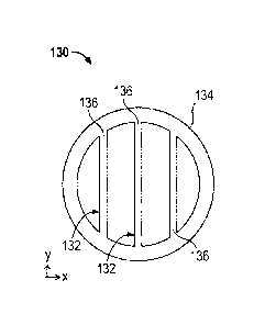
FIG. 2 shows a cross-section of the multi-channel flow tube 130 shown in FIG.
1
according to an embodiment. A reference coordinate system with x and y-axes is
also
shown. The multi-channel flow tube 130 includes two or more fluid channels
132. As
shown in FIG. 1, the two or more fluid channels 132 are disposed within a tube
wall
134. The two or more fluid channels 132 are defined by channel divisions 136
within
the tube wall 134. The channel divisions 136 lie within a plane that is
parallel with a
single axis. As shown, the channel divisions 136 are formed in planes
perpendicular to
the x-axis of the reference coordinate system.
FIG. 3 shows a cross-section of another multi-channel flow tube 330 according
to an embodiment. A reference coordinate system with x and y-axes is also
shown. The
multi-channel flow tube 330 includes two or more fluid channels 332. As shown
in FIG.
3, the two or more fluid channels 332 are disposed within a tube wall 334. The
two or
more fluid channels 332 are defined by channel divisions 336 within the tube
wall 334.
Some of the channel divisions 336 lie within planes that are parallel with the
x-axis, and
others of the channel divisions 336 lie within planes that are parallel with
the y-axis.
Some channel divisions 336 are perpendicular to other channel divisions 336.
There
may be channel divisions 336 such that some channel divisions 336 are parallel
with one
of the x and y-axis and perpendicular to the other of the x and y-axis of the
reference
coordinate system.
FIG. 4 shows a cross-section of another multi-channel flow tube 430 according
to an embodiment. A reference coordinate system with x and y-axes is also
shown. The
multi-channel flow tube 430 includes two or more fluid channels 432. Only two
of the
two or more fluid channels 432 are referenced for clarity. As shown in FIG. 4,
the two
or more fluid channels 432 are disposed within a tube wall 434. The two or
more fluid
channels 432 are defined by channel tubes 436 within the tube wall 434. The
multi-
channel flow tube 430 is a tube bundle. In other words, the multi-channel flow
tube 430
is formed by a bundle of the channel tubes 436 configured to move as an
integral
structure. More specifically, the upper two and lower two of the channel tubes
436 each
form a plane that is parallel with the x-axis of the reference coordinate
system.
Similarly, the left two and the right two of the channel tubes 436 each form a
plane that
is parallel to the y-axis of the reference coordinate system.
Date Recue/Date Received 2020-04-15
FIG. 5 shows a cross-section of another multi-channel flow tube 530 according
to an embodiment. The multi-channel flow tube 530 includes two or more fluid
channels
532. Only two of the two or more fluid channels 532 are referenced for
clarity. As
shown in FIG. 5, the two or more fluid channels 532 are disposed within a tube
wall
534. The two or more fluid channels 532 are defined by channel tubes 536
disposed
within the tube wall 534. The multi-channel flow tube 530 is a tube bundle. In
other
words, the multi-channel flow tube 530 is formed by a bundle of the channel
tubes 536
configured to move as an integral structure. The channel tubes 536 are
disposed
concentrically about a longitudinal axis of the tube wall 534.
In these and other embodiments, the two or more fluid channels 132, 332-532
are
configured to bend in the same direction as an integral structure in response
to a drive
signal applied to the driver 180. For example, with reference to the two or
more fluid
channels 332 shown in FIG. 3, the tube wall 334 surrounds the two or more
fluid
channels 332. As a result, the tube wall 334 deforms (e.g., bends) in response
to a force
applied by the driver 180 to the tube wall 334. As shown in FIG.1, the driver
180
applies the force in the direction perpendicular to the planes formed by the
channel
divisions 136. The channel divisions 136 have a planar shape that extends
along the
longitudinal length of the multi-channel flow tube 130.
The two or more fluid channels 132, 332-532 extend longitudinally parallel to
one another and the tube wall 134, 334-534. That is, a longitudinal length
(e.g., a length
extending between flow tube mounting blocks 120, 120') of the two or more
fluid
channels 132, 332-532 and the tube wall 134, 334-534 are parallel with each
other. The
longitudinal length may be the same as a vibratory portion of the multi-
channel flow
tube 130, 330-530 (e.g., the length between the brace bars 140, 140').
However, in
alternative embodiments, the two or more fluid channels may not be parallel to
one
another and/or a tube wall. For example, alternative two or more fluid
channels may be
twisted relative to each other and/or the tube wall. Additionally or
alternatively, the
longitudinal length of the tube wall may not be equal to a longitudinal length
of the two
or more fluid channels.
The cross sections shown in FIGS. 2-5 extend along the longitudinal length of
the multi-channel flow tubes 130, 330-530. That is, the cross-sections are
consistent
from approximately the inlet end 104 and the outlet end 104' of the vibratory
meter 5.
11
Date Recue/Date Received 2020-04-15
However, in alternative embodiments, the cross-sections may vary over the
longitudinal
length of the multi-channel flow tubes 130, 330-530. For example, an
alternative multi-
11/a
Date Recue/Date Received 2020-04-15
CA 03024388 2018-11-15
WO 2017/200518 PCT/US2016/032644
channel flow tube may include the cross-section shown in FIG. 2 near an inlet
end and
an outlet end and the cross-section shown in FIG. 3 in the center portion of
the
alternative flow tube. In another alternative embodiment, the cross sections
can spiral
along the longitudinal length of the multi-channel flow tube 130, 330-530.
Spiraling the
cross-section can cause the multi-channel flow tube 130, 330-530 to act as a
centrifuge
on the multi-phase fluid and force the heavy liquid to the one side (e.g.,
outside) of each
of the two or more fluid channels 132, 332-532.
Some of the benefits achieved with the use of the multi-channel flow tube 130,
330-530 only require cross-sections in certain locations within the multi-
channel flow
tube 130, 330-530, for example, in locations of large vibratory deformation.
Thus, in
certain embodiments, cross-sections may only be employed in specific locations
within
the multi-channel flow tube 130, 330-530. Other locations could employ a
circular cross
section without the two or more fluid channels 132, 332-532, so as to reduce
the
pressure drop through the multi-channel flow tube 130, 330-530.
The cross-sections shown in FIGS. 2-5 are also symmetrical. That is, the cross-
sections are mirror images around the x-axis and the y-axis of the reference
coordinate
system. However, in alternative embodiments the cross-sections may be non-
symmetric
about the x and/or y-axis of the reference coordinate system. For example, an
alternative
flow tube may have double axis divisions in a top portion similar to those
shown in FIG.
3 and single axis divisions in the lower portion of the flow tube similar to
those shown
in FIG. 2. The cross-sections may also include divisions from, for example,
the four
fluid channels 432 shown in FIG. 4 to the seven fluid channels 532 shown in
FIG. 5
along the length of the alternative flow tube.
The cross-sections shown in FIGS. 2-5 may be formed by using any suitable
materials and methods. For example, the cross sections shown in FIGS. 2 and 3
may be
formed as a single integral structure by 3-D printing, extrusion, etc. The
cross-sections
shown in FIGS. 4 and 5 may be formed by inserting the channel tubes 436-536
into the
tube wall 434-534. After the channel tubes 436-536 are inserted into the tube
wall 434-
534, multiple mandrels may be inserted into the channel tubes 436-536 to press
against
the wall while the multi-channel flow tubes 130, 330-530 are bent. This can
ensure that
the channel tubes 436-536 do not collapse. The material used to form the multi-
channel
flow tubes 130, 330-530 may be any suitable material, such as plastic, metal,
etc.
12
CA 03024388 2018-11-15
WO 2017/200518 PCT/US2016/032644
The materials and methods used to form the cross-sections shown in FIGS. 2-5
can form the two or more fluid channels 132, 332-532 as the single integral
structure.
For example, by extruding the multi-channel flow tube 130 shown in FIG. 2, the
tube
wall 134 and channel divisions 136 are an integral structure. For example, the
tube wall
.. 134 and channel divisions 136 are formed as a single piece or complete
structural whole.
Similarly, the channel tubes 436-536 and tube wall 434-534 may also be formed
as an
integral structure by, for example, adhering the channel tubes 436-536 and
tube wall
434-534 to each other. The channel tubes 436-536 and tube wall 434-534 may be
adhered to each other with brazing, adhesives, friction welding, etc.
By forming the two or more fluid channels 132, 332-532 as the integral
structure,
the vibratory meter 5 may be inexpensive to manufacture and be reliable. For
example,
stiffening members are not used between the two or more fluid channels 132,
332-532.
By eliminating stiffening members, the associated manufacturing steps may also
be
eliminated. In addition, friction forces between each of the two or more fluid
channels
132, 332-532 may not be present. For example, the channel tubes 436-536 shown
in
FIGS. 4 and 5 do not rub against each other or the tube wall 434, 534 as the
flow tubes
430-530 are vibrated. This can prevent inter-tubal erosion, thereby extending
the
operating life of the flow tubes 430-530. Avoidance of friction forces in
vibrating
members may also be important to obtaining accurate mass flow and density
.. measurements with a Coriolis flow meter.
As can be appreciated, an effective tube diameter of the multi-channel flow
tubes
130, 330-530 is smaller than the diameter of the tube wall 134, 334-534. That
is, the
effective diameter of the multi-channel flow tubes 130, 330-530 may be about
the
diameter of the two or more fluid channels 132, 332-532. For example, the
effective
diameter of the multi-channel flow tube 530 shown in FIG. 5 may be about 1/3
of the
diameter of the tube wall 134, 334-534. Accordingly, the multi-channel flow
tubes 130,
330-530 may provide about or less than the capacity of a standard flow tube
(i.e., flow
tubes without the two or more fluid channels 132, 332-532) while realizing
benefits
associated with the smaller effective diameter.
Beneficial effects
The multi-channel flow tube 130, 330-530 addresses the performance issues
related to compressibility, decoupling, and flow profile effects. In addition,
benefits
13
CA 03024388 2018-11-15
WO 2017/200518 PCT/US2016/032644
related to pressure containment and erosion may also be realized. These
benefits are
explained in more detail in the following.
Compressibility
Vibratory meters require that the fluid flowing through the flow tubes move
with
the flow tubes during oscillation at the meter assembly's natural frequency.
High
frequency meters typically have not worked well for gas or entrained gas
applications,
due in part to the fact that the fluid moves too far on each oscillation.
These
compressibility, or velocity of sound, effects cause positive mass flow and
density
errors, which are predicted by the following closed-form equations (1) and
(2), which
are reproduced from Hemp J. and Kutin J., "Theory of Errors in Coriolis
flowmeter
readings due to compressibility of the fluid being metered", Flow Measurement
and
Instrumentation, 17: 359-369. In the following closed-form equations (1) and
(2), co is
the angular oscillation frequency, d is the inner diameter of the flow tube,
and c is the
speed of sound of the process fluid. Note that errors increase with increasing
tube
diameter.
10).12
= ( )
PV0S,err X 100 (1)
X 100
rilVOS,err = ( ¨wc1)2
(2)
2 2c
While the forms of these equations appear simple, it may be difficult to use
them to
compensate for compressibility effects in practice. Even in single-phase gas
or
compressible liquid applications, it is necessary to know the speed of sound
of the
process fluid in order to compensate. In the case of multiphase applications,
the mixture
speed of sound, c, depends on a long list of difficult-to-measure parameters,
including
gas and liquid speeds of sound, gas and liquid densities, and gas void
fraction.
However, the multi-channel flow tube 130, 330-530 can reduce or eliminate
these problems because the effective tube diameter, d, can be considerably
less than a
standard flow tube. In the multi-channel flow tube 130, 330-530, the two or
more fluid
channels' 132, 332-532 diameter equal to 115th of the diameter of the tube
wall 134, 334-
534 may result in a 25 times reduction in errors due to velocity of sound
effects. In other
words, the multi-channel flow tube 130, 330-530 can eliminate velocity of
sound
14
CA 03024388 2018-11-15
WO 2017/200518 PCT/US2016/032644
effects. This would allow a designer of a vibratory meter to accept a higher
vibration
frequency (with associated benefit to meter compactness and cost) without
sacrificing
performance related to compressible liquids, gases, or multiphase mixtures.
Decoupling effects
Vibratory meters typically require that the fluid flowing through them move
directly with the flow tubes during vibration. When gas bubbles are introduced
into a
liquid stream, this assumption is no longer valid as there is relative motion,
or
"decoupling," between the two phases. A model can predict errors for specific
fluid
mixture properties. However, the model may require many unmeasured parameters
as
.. inputs, including bubble size and liquid viscosity, making direct
compensation of errors
difficult. The model and experimental results show that vibratory meters with
relatively
small diameter flow tubes typically perform better and have less measurement
error.
This is explained by the fact that one of the assumptions made in the
decoupling
model is that the fluid inside the tube represents a uniform distribution of
bubbles in an
infinite liquid medium. It does not account for a reduction in decoupling due
to the
presence of nearby tube walls. A numerical study of wall effects in
oscillatory flow by
Fischer PF, Leaf GK, and Restrepo DA. "Influence of wall proximity on the lift
and drag
of a particle in an oscillatory flow", Journal of Fluids Engineering. 127:583-
595 (2005)
shows that wall effects are negligible unless the particle is less than two
radii from the
wall. Stated another way, wall effects become important only when the ratio of
particle
diameter to tube diameter approaches unity. An experimental study by Coimbra
et al.,
"An experimental study on stationary history effects in high-frequency Stokes
flows", I
Fluid Mech. 504:353-363, confirms these results. The experiment involves
oscillation of
a tethered particle in a fluid column at frequencies up to 80 Hz. For many
vibratory
meters, bubbles are small compared to the tube diameter, and wall effects are
negligible,
resulting in unrestricted decoupling and large errors.
FIG. 6 shows a graph 600 of a mass error percent reading of a standard flow
tube
having a relatively small diameter of 1/4". The graph 600 includes an average
void
fraction percentage axis 610 and a mass error percent reading axis 620. The
graph 600
includes mass error reading plots 630 that illustrate variation in the mass
error reading
relative to the average void fraction percentage. The mass error reading plots
630
include mass error readings for water, mineral oil, and mineral oil with 10%
water cut.
CA 03024388 2018-11-15
WO 2017/200518 PCT/US2016/032644
The mass error readings for the various fluids range from less than 5% to -15%
and
drops to less than -10% at greater than 60% void fraction. The mass error
reading plots
630 show that, in smaller diameter standard flow tubes, such as 'A" diameter
flow tubes,
the bubbles are constrained from decoupling by the presence of the tube walls,
leading
to less error, over a wide range of void fractions.
Accordingly, the multi-channel flow tubes 130, 330-530, which include the two
or more fluid channels 132, 332-532 that have a diameter less than the
diameter of the
tube wall 134, 334-534 (e.g., a 1/5th inch fluid channel in a 1-inch tube
wall), can result
in usable measurements from fluids with greater than 50% gas void fraction.
The
measurement accuracy of total mass flow rate may be comparable to that of
dedicated
multiphase meters that can cost many hundreds of thousands of dollars and
employ
nuclear technology, which may be undesirable. The same performance can be
achieved
in the vibratory meter 5 with the multi-channel flow tubes 130, 330-530, which
can
prevent decoupling from occurring, without the expense and hazards that may be
associated with more complex technologies. For example, the multi-channel flow
tubes
130, 330-530 with an effective tube diameter equal to 1/10th of the diameter
of the tube
wall 134, 334-534 would allow performance similar to that found in smaller
diameter
standard tubes and without costing hundreds of thousands of dollars and
without
employing nuclear technology.
Decoupling also causes asymmetric damping because of the secondary motion of
bubbles moving through the base liquid in the direction of tube oscillation.
Asymmetric
damping from the inlet to outlet of a vibratory flow meter with a standard
flow tube can
cause large false mass flow readings. One cause of asymmetric bubble
distribution is
buoyancy, which can cause bubbles to be trapped in one part of the standard
flow tube
and not the other parts. If the bubble distribution is asymmetric along the
length of the
tube, then asymmetric damping occurs. High flow rate minimizes this
phenomenon,
keeping the mixture homogeneous, but high flow rate also results in increased
pressure
drop and can cause flashing due to decreased static pressure. In addition,
even with high
flow rate, asymmetric damping may always be present to some degree. In the
multi-
channel flow tubes 130, 130', this damping may be reduced because the entire
cross-
section of the multi-channel flow tubes 130, 130' may be either liquid or gas,
but may
not be a mixture of both. Additionally, if the bubble takes up the entire
cross section,
16
CA 03024388 2018-11-15
WO 2017/200518 PCT/US2016/032644
then the bubble is forced to move at the same flow rate as the liquid. As a
result, there
can no longer be gas hold up on one side of the vibratory meter 5, and the gas
may be
more evenly distributed down the length of the multi-channel flow tubes 130,
130'.
Flow profile effects
The magnitude of error due to a velocity profile effect may also depend on
Reynolds Number, Stokes Number, and tube geometry. Some of the variables that
define these non-dimensional parameters are dependent on fluid properties.
However,
the magnitude of flow profile effect is strongly dependent on the ratio of the
length (L)
of the flow tube to its diameter (D). Larger vibratory meters have a
relatively low L/D
ratio. Typically, vibratory meters with LID ratios above 25 have no measurable
flow
profile effect. The multi-channel flow tubes 130, 330-530, because they have a
lower
effective diameter, could be employed to increase the LID ratios of higher
flow rate
vibratory meters to eliminate flow profile effect in larger vibratory meters.
In fact, a
multi-channel flow tube 130 with individual tube diameters even one half as
large as the
tube wall 134 would result in LID ratios above 25 for vibratory meters of many
different
sizes.
Pressure containment benefits
Another benefit of the multi-channel flow tube 130 is a higher pressure
rating. In
the standard flow tube without the two or more fluid channels, as tube
diameter
decreases, pressure rating increases (Hoop Stress = Pressure * Radius /
Thickness). The
standard tubes with large diameters typically have thicker walls, reducing
flow
sensitivity and performance. However, the multi-channel flow tube 130 resolves
this
problem by employing two or more fluid channels 132, each with a pressure
rating that
may be higher than a single tube of equivalent flow area. Additionally,
pressure effect
on flow and density would be substantially reduced. However, the multi-channel
flow
tubes 330-530 shown in FIGS. 3-5 may have improved pressure containment over
the
single axis division multi-channel flow tube 130 shown in FIG. 2.
Erosion
Erosion may also be reduced in the tube bundle meter. Erosion is typically
highly
dependent on Reynolds number, which increases with increasing tube diameter.
At
lower Reynolds numbers (smaller effective diameter), erosion is reduced. Also,
because
17
CA 03024388 2018-11-15
WO 2017/200518 PCT/US2016/032644
the multi-channel flow tubes 130, 330-530 can reduce or eliminate asymmetric
damping
problems, fluid velocities need not be kept as high to obtain good performance
in gas
entrainment applications. This results in a lower Reynolds number, and thus
less
erosion.
Due to these and other benefits, the measurements obtained from vibratory
meters employing a multi-channel flow tube, such as the vibratory meter 5
described in
the foregoing, may be more accurate than standard flow tubes without the two
or more
fluid channels. Exemplary measurements are described in the following with
reference
to FIGS. 7 - 12.
Percent error data
FIGS. 7 through 12 described in the following show density, mass, and volume
flow rate errors associated with a standard flow tube without two or more
fluid channels
(FIGS. 7, 9, and 11 labeled with "baseline") and single axis division multi-
channel flow
tube shown in the FIG. 2 (FIGS. 8, 10, and 12 labeled with "single axis
division"). The
data shown in the FIGS. 7 through 12 was obtained from water flowing through a
1-inch
flow meter with a circular cross section.
Density errors
FIGS. 7 and 8 are graphs 700, 800 directed to density errors. The graphs 700,
800 include gas void fraction axes 710, 810, which is the abscissa, and a
percent mixture
density error axes 720, 820, which is the ordinate. The gas void fraction axes
710, 810
range from 0 to 25%. The percent mixture density error axes 720, 820 range
from -30%
to 5%.
FIG. 7 shows the graph 700 illustrating a relationship between density errors
and
gas void fraction for a standard flow tube without the two or more fluid
channels
("density baseline"). The graph 700 has data plots 730 of data for different
flow rates,
ranging from 0.5 nils to 10 m/s. The data plots 730 indicate that the percent
mixture
density error is relatively low at low gas void fractions. However, the
percent mixture
density error increases at higher gas void fraction percentages. For example,
at a flow
rate of 10 m/s, the percent mixture density error increases from less than 1%
to about
25%. The percent mixture density error is also highly dependent on fluid
velocity
because of changing bubble size and the presence of asymmetric damping. Here,
the
18
CA 03024388 2018-11-15
WO 2017/200518 PCT/US2016/032644
error increases with increased flow rate, while in other situations, the
opposite trend is
observed.
FIG. 8 shows the graph 800 illustrating a relationship between density errors
and
gas void fraction for a multi-channel flow tube with the single axis division
shown in
FIG. 3 according to an embodiment ("density single axis division"). The graph
800 has
data plots 830 of data for different flow rates, ranging from 0.5 m/s to 10
m/s. The data
plots 830 indicate that the percent mixture density error is relatively low at
low gas void
fractions. The percent mixture density error increases at higher gas void
fraction
percentages. However, the percent mixture density error does not increase as
much as
shown in FIG. 7. For example, at a flow rate of 10 m/s, the percent mixture
density error
increases from less than 1% to less than 5%, in contrast to the increase from
less than
1% to about 25% shown in FIG. 7.
Mass flow errors
FIGS. 9 and 10 are graphs 900, 1000 directed to mass flow errors. The graphs
900, 1000 include gas void fraction axes 910, 1010, which is the abscissa, and
a percent
mixture mass flow error axes 920, 1020, which is the ordinate. The gas void
fraction
axes 910, 1010 range from 0 to 25%. The percent mixture mass flow error axes
920,
1020 range from -30% to 20%.
FIG. 9 shows a graph 900 illustrating a relationship between mass flow rate
errors and gas void fraction for a standard flow tube without the two or more
fluid
channels ("mass baseline"). The graph 900 has data plots 930 of data for
different flow
rates, ranging from 0.5 m/s to 10 m/s. The data plots 930 indicate that the
percent
mixture mass flow error is relatively low at low gas void fractions. However,
the percent
mixture mass flow error increases at higher gas void fraction percentages. The
percent
mixture mass flow error is highly erratic and variable with flow rate. For
example, at a
flow rate of 10 m/s, the percent mixture mass flow error increases from less
than 1% to
about 15%, with a maximum to minimum span of about 30%.
FIG. 10 shows a graph 1000 illustrating a relationship between mass flow rate
errors and gas void fraction for a multi-channel flow tube with the single
axis division
shown in FIG. 2 according to an embodiment ("mass single axis division"). The
graph
1000 has data plots 1030 of data for different flow rates, ranging from 0.5
m/s to 10 m/s.
The data plots 1030 indicate that the percent mixture mass flow error is
relatively low at
19
CA 03024388 2018-11-15
WO 2017/200518 PCT/US2016/032644
low gas void fractions. The percent mixture mass flow error increases at
higher gas void
fraction percentages. However, the percent mixture mass flow error does not
increase as
much as shown in FIG. 9. For example, at a flow rate of 10 m/s, the percent
mixture
mass flow error increases from less than 1% to less than 5%, with a maximum to
minimum span of about 30%. Furthermore, the span of 30% between maximum and
minimum errors at high void fraction observed in FIG. 10 is far greater than
the span of
about 5% shown in FIG. 11. In other words, the errors are not only smaller,
but less
erratic and less variable with changing flow rate.
Volume flow errors
FIGS. 11 and 12 are graphs 1100, 1200 directed to volume flow errors. The
graphs 1100, 1200 include gas void fraction axes 1110, 1210, which is the
abscissa, and
a percent mixture volume flow error axes 1120, 1220, which is the ordinate.
The gas
void fraction axes 1110, 1210 range from 0 to 25%. The percent mixture volume
flow
error axes 1120, 1220 ranges from -30% to 30%.
FIG. 11 shows a graph 1100 illustrating a relationship between volume flow
rate
errors and gas void fraction for a standard flow tube ("volume baseline"). The
graph
1100 has data plots 1130 of data for different flow rates, ranging from 0.5
m/s to 10 m/s.
The data plots 1130 indicate that the percent mixture volume flow error is
relatively low
at low gas void fractions. However, the percent mixture volume flow error
increases at
higher gas void fraction percentages. The percent mixture volume flow error is
highly
erratic and variable with flow rate. For example, at a flow rate of 10 m/s,
the percent
mixture volume flow error increases from less than 1% to about 15%, with a
maximum
to minimum span of about 30%.
FIG. 12 shows a graph 1200 illustrating a relationship between volume flow
rate
errors and gas void fraction for a multi-channel flow tube with the single
axis division
shown in FIG. 2 according to an embodiment ("volume single axis division").
The graph
1200 has data plots 1230 of data for different flow rates, ranging from 0.5
m/s to 10 m/s.
The data plots 1230 indicate that the percent mixture volume flow error is
relatively low
at low gas void fractions. The percent mixture volume flow error increases at
higher gas
void fraction percentages. The percent mixture volume flow error also
increases as the
flow rate increases. However, the percent mixture volume flow error does not
increase
as much as shown in FIG. 11. For example, at a flow rate of 10 m/s, the
percent mixture
CA 03024388 2018-11-15
WO 2017/200518 PCT/US2016/032644
volume flow error increases from less than 1% to less than 10%, in contrast to
the
increase from less than 1% to about 15% shown in FIG. 11. As can be
appreciated when
comparing FIGS. 11 and 12, the multi-channel flow tube 130 with the single
axis
division shown in FIG. 2 has at least a 3 times improvement over a standard
flow tube.
In addition, data from FIG. 8 can be used to compensate for the flow rate
error in
the mass and volume flow rate measurements shown in FIGS. 10 and 12. The
mixture
density error illustrated by the data plots 830 is consistently less than 5%
over a range of
gas void fractions and flow rates. Accordingly, the gas void fraction of a
liquid-gas
mixture can be accurately correlated with a density measurement. In addition,
the mass
and volume flow rates shown in FIGS. 10 and 12 are precise within about 10% at
each
flow rate. Since the gas void fraction can be accurately correlated with the
density
reading and the mass and volume flow rates are precise, then the mass and/or
volume
flow rates can be measured and compensated by using the gas void fraction
correlated
with the density reading, which is described in more detail in the following
with
reference to the methods shown in FIGS. 13 and 14.
Methods
FIG. 13 shows a method 1300 of measuring a fluid with a multi-channel flow
tube. As shown in FIG. 13, the method 1300 begins by separating the fluid into
two or
more fluid channels in a multi-channel flow tube in step 1310. The two or more
fluid
channels are surrounded by a tube wall. The tube wall and two or more fluid
channels
are formed as a single integral structure. For example, the multi-channel flow
tube may
be one of the multi-channel flow tubes 130, 330-530 described with reference
to FIGS.
1-5. In step 1320, the method 1300 applies a drive signal to a driver coupled
to the
multi-channel flow tube. The driver is configured to vibrate the multi-channel
flow tube.
The method 1300, in step 1330, bends the two or more fluid channels and the
tube wall
in the same direction as the single integral structure in response to the
drive signal
applied to the driver. In step 1340, the method 1300 measures a deflection of
the multi-
channel flow tube with a sensor attached to the multi-channel flow tube.
The step 1310 of separating the fluid into the two or more fluid channels may
include separating a gas component of the fluid into one of the two or more
fluid
channels. For example, the fluid may be a multi-component fluid with, for
example, slug
flow. A slug in the slug flow may be separated from the multi-component fluid
into the
21
CA 03024388 2018-11-15
WO 2017/200518 PCT/US2016/032644
one of the two or more fluid channels. The gas component can also fill the one
of the
two or more fluid channels. Separating the gas component can ensure that the
separated
gas component vibrates or deflects the same as the liquid portion of the
liquid portion of
the multi-component fluid flow.
Applying the drive signal, in step 1320, to the multi-channel flow tube can
include applying a drive signal to a tube wall with channel divisions within
the tube
wall, channel tubes that are affixed to each other, a tube wall that surrounds
channel
tubes, etc. For example, with reference to the multi-channel flow tubes 130,
130' shown
in FIGS. 1 and 2, the drive signal is applied to the driver 180, which is
coupled to the
tube wall 134. Similarly, the driver 180 may be coupled to the tube walls 434,
534
shown in FIGS. 4 and 5. However, the drive signal may also be applied to the
channel
tubes 436, 536 also shown in FIGS. 4 and 5, where, for example, the tube walls
434, 534
leave a portion of the channel tubes 436, 536 exposed.
As a result of the drive signal, the multi-channel flow tube can bend as the
single
integral structure in the same direction. For example, the multi-channel flow
tubes 130,
130', 330 described with reference to FIGS. 1-3 bend as a single integral
structure in the
direction of the force applied by the driver 180 because the tube wall 134,
334 and
channel divisions 136, 336 are formed as the single integral structure by, for
example,
extruding or 3-D printing the tube wall 134, 334 and the channel divisions
136, 336.
Accordingly, the force applied by the driver 180 to the multi-channel flow
tube 130, 330
causes the tube walls 134, 334 and the two or more fluid channels 132, 332 to
deflect by
substantially the same amount. Similarly, the two or more fluid channels 432,
532
shown in FIGS. 4 and 5 also bend in the same direction due to the force
applied by the
driver 180 to the tube walls 434, 534 or the channel tubes 436, 536. The
channel tubes
436, 536 and the tube wall 434, 534 can bend as the single integral structure
due to, for
example, brazing between the channel tubes 436, 536 and between the tube wall
434,
534 and the channel tubes 436, 536.
The deflection of the multi-channel flow tube may be measured by pick-off
sensors that are coupled to the multi-channel flow tube. For example, with
reference to
the multi-channel flow tubes 130, 130' shown in FIGS. 1 and 2, the pick-off
sensors
1701 and 170r can measure a deflection of the multi-channel flow tubes 130,
130' where
the pick-off sensors 1701 and 170r are located. The deflection where the pick-
off sensors
22
1701 and 170r are located is due to the deforming of the multi-channel flow
tube 130,
130' caused by the drive signal applied to the driver 180. Similar to the
driver 180, the
pick-off sensors 1701 and 170r can be coupled to the tube walls 134, 334 or
the channel
tubes 436, 536.
FIG. 14 shows another method 1400 of measuring a fluid with a multi-channel
flow tube. As shown in FIG. 14, the method 1400 measures a density of a fluid
using a
multi-channel flow tube in step 1410. The multi-channel flow tube used in step
1410
may be the multi-channel flow tube 130 shown in FIG. 2, which is a single axis
division
multi-channel flow tube, although any suitable multi-channel flow tube may be
employed. In step 1420, a gas void fraction is determined using the measured
density. In
step 1430, the method 1400 compensates a flow rate measurement, such as a mass
or
volume flow rate measurement, using the gas void fraction.
In step 1410, the density measurement may be performed using the deflection
measurements generated by pick-off sensors, the deflection measurements as
described
with reference to FIG. 13. Due to using the multi-channel flow tube, the
density
measurements can have an error rate that is less than 5% and is consistent
over a range
of flow rates and gas void fractions. Accordingly, the gas void fraction of a
mixed phase
fluid, such as water and air, can be determined from the density measurement
combined
with, for example, knowledge of the liquid density. The liquid density can be
found
during periods of no gas, known from the data stored in the meter electronics
20, entered
by the customer, etc.
In step 1420, the gas void fraction can be determined using the measured
density
by using, for example, the data plots 830 and/or the interpolation of the data
plots 830,
although any suitable correlation between the measured density and the gas
void
fraction may be employed. For example, the processor in the meter electronics
20 can
use the measured density to look up the correlated gas void fraction in a look
up table. A
processor in the meter electronics 20 can interpolate (e.g., linear,
polynomial, etc.)
between each data point in the data plots 830 to provide the correlation
between the
density measurement and the gas void fraction. The interpolation can also be
stored in
the memory as a formula, look up table, etc.
23
Date Recue/Date Received 2020-04-15
In step 1430, the measured flow rate may be compensated with the gas void
fraction by using, for example, an additional look up table, formula or the
like. The look
up table, formula, or the like, may correlate a flow rate error, such as a
mass or volume
23/a
Date Recue/Date Received 2020-04-15
CA 03024388 2018-11-15
WO 2017/200518 PCT/US2016/032644
flow rate error, with a gas void fraction. For example, with reference to FIG.
10, the gas
void fraction of 20% may have a correlated mass flow rate error of about -6%.
The
measured mass flow rate can be compensated by multiplying the measured mass
flow
rate by the correlated mass flow rate error and adding the result to the
measured mass
flow rate. This may be referred to as the compensated measured mass flow rate.
A
compensated measured volume flow rate may be determined in a similar manner.
The measured mass fl ow rate may be continuously compensated during operation
using predetermined correlations between the measured density and the gas void
fractions and between the flow rate error and gas void fraction. For example,
during
manufacturing or calibration, the vibratory meter 5 can measure density and
flow rates
of the fluid over a range of gas void fractions and flow rates. The measured
density and
flow rates can be stored in the meter electronics 20 as look up tables,
formulas, or the
like. The flow rate errors can also be determined by using, for example,
another
reference flow meter during manufacturing or calibration. The measurements
from the
reference flow meter may be compared to the flow rates measured by the
vibratory
meter 5 to determine the flow rate error. During operation, the meter
electronics 20 may
continuously correlate the measured density with the gas void fraction and
compensate
the measured flow rate as described in the foregoing with reference to FIG.
14.
The embodiments described above provide the vibratory meter 5 with the multi-
channel flow tubes 130, 330-530. The multi-channel flow tubes 130, 330-530
include
two or more fluid channels 132, 332-532. The two or more fluid channels
provide the
effective diameter of the multi-channel flow tubes 130, 330-530 that is less
than the
diameter of the tube wall 134, 334-534. Due to the effective diameter of the
multi-
channel flow tube 130, 330-530 being smaller than the diameter of the tube
wall 134,
334-534, the performance issues related to compressibility, decoupling, and fl
ow profile
effects may be improved. In addition, the pressure containment may be
improved. As a
result, the vibratory meter 5 may be less expensive and use simpler
manufacturing steps
than many multiphase metering technologies, while also providing more accurate
multiphase flow rate measurements.
For example, the multi-channel flow tubes 130, 330-530 may provide accurate
density measurements over a range of gas void fractions and flow rates. The
density
measurements can therefore be used to accurately determine the gas void
fraction of the
24
CA 03024388 2018-11-15
WO 2017/200518 PCT/US2016/032644
multiphase fluid. In addition, the multi-channel flow tubes 130, 330-530 can
also
provide precise mass or volume flow rate measurements. Accordingly, the mass
or
volume flow rates can be compensated using the gas void fractions determined
by the
meter electronics 20. As a result, the mass or volume flow rate measurements
of
multiphase fluids can be accurate without the expense associated with other
multiphase
technologies.
The detailed descriptions of the above embodiments are not exhaustive
descriptions of all embodiments contemplated by the inventors to be within the
scope of
the present description. Indeed, persons skilled in the art will recognize
that certain
.. elements of the above-described embodiments may variously be combined or
eliminated
to create further embodiments, and such further embodiments fall within the
scope and
teachings of the present description. It will also be apparent to those of
ordinary skill in
the art that the above-described embodiments may be combined in whole or in
part to
create additional embodiments within the scope and teachings of the present
description.
Thus, although specific embodiments are described herein for illustrative
purposes, various equivalent modifications are possible within the scope of
the present
description, as those skilled in the relevant art will recognize. The
teachings provided
herein can be applied to multi-channel flow tubes and not just to the
embodiments
described above and shown in the accompanying figures. Accordingly, the scope
of the
embodiments described above should be determined from the following claims.