Note : Les descriptions sont présentées dans la langue officielle dans laquelle elles ont été soumises.
RADIOACTIVE WASTE RECYCLING PLANT
The alleged invention is related to nuclear power generation technologies
S and can be used for recycling of low and medium radioactivity waste, in
particular, nuclear waste from VVER and RBMK reactors and other nuclear
installations.
A system for treatment of radioactive and toxic waste which contains
cellulose, polymeric compounds, resin, PVC and non-flammable admixtures, such
3.o as glass and metals is known wherein the generated combustion residues are
further melted to transform into a solid mass ( patent RF No 2107347).
Disadvantages of this system are as follows: low capacity of the feed system,
large volume of flue gases, insufficient purification of flue gases from
aerosol
impurities and radioactive nuclides, lack of automatic or automated mode for
15 recycling of radioactive waste.
The closest equivalent of the alleged invention is a nuclear waste recycling
installation described in patent RF No 2320038, the installation contains the
following equipment: a feed system, a plasma shaft-type furnace with a melter
located in the hearth of the furnace and a slag discharge unit connected to
the
zo receiving tank for molten slag; an air supply unit to the furnace and
pyrolysis gas
combustion chamber; evaporative heat exchanger for sharp reduction of flue gas
temperature; gas purification unit with a sock-type filter, a heat exchanger
and a
scrubber, pumps and tanks for chemical agents and recycled products, fittings.
Disadvantages of this technical solution are as follows: lack of possibility
to
25 alter or reconfigure the nuclear waste recycling process depending on
the type of
waste; low efficiency of waste recycling and low wear-resistance due to
critically
high operational parameters.
CA 3024945 2018-11-22
The objective of the alleged invention is to extend the functionality, enhance
wear-resistance and efficiency of the recycling plant. The technical result of
the
invention is to design a flexible operation mode in which nuclear waste with
different radioactivity level would be recycled in automatic or automated
mode,
.. and to ensure increased wear-resistance of the plant components.
This technical result is achieved in the radioactive waste recycling plant
which consist of the following components: a waste feed unit, a plasma shaft-
type
furnace with a melter in the hearth of the furnace and a slug discharge unit
connected with a receiving tank for molten slug; an air supply unit delivering
air
to the furnace to a pyrolysis gas combustion chamber; an evaporative heat
exchanger for sharp reduction of the flue gases temperature; a gas
purification
unit with a sock-type filter; a heat-exchanger and a scrubber; pumps and tanks
for
agents and recycled products; fittings; the recycling plant (in accordance
with the
invention) is additionally equipped with, at least, one control module which
is
electrically connected to the slug discharge control module, an interior
environment control module, an equipment status control module and, at least,
one gas analytical module. The control module is electrically connected with
the
electric hardware of a waste feed unit, a plasma shaft-type furnace, a
receiving
tank for molten slug and with the electric hardware of the air supply unit
which
delivers the air to the furnace and to the combustion chamber, and the slug
discharge control is electrically connected with the electric hardware of the
slug
discharge unit.
A control module for a slag discharge unit may include a digital video
recorder, a temperature sensor for discharged slag, optical monitoring sensors
located inside the receiving tank for molten slag; a light alarm system with
lighting
columns and an emergency button.
An interior environment control module may include, at least, temperature,
pressure, flow and rarefication sensors, one sensor of each category.
2
CA 3024945 2018-11-22
An equipment status control module may include, at least, one fittings
position transmitter and one pump control sensor.
A gas analytical module may include the following sensors: measuring
sensors for gas concentration (oxygen, carbon monoxide, carbon dioxide,
s nitrogen oxide, nitrogen dioxide, aggregate concentration of nitrogen
oxide,
sulfur dioxide and aggregate concentration of hydrocarbons). The location for
installation of the gas analytical module can chosen to provide for the
monitoring
of pyrolysis gas composition in the gas stack between the plasma shaft-type
furnace and the combustion chamber, and/or to provide for the monitoring of
3.0 flue gases in the gas stack between the combustion chamber and the
evaporative
heat exchanger, and/or at the outlet of the recycling plant.
Control module can be equipped by a data storage unit and data displaying
screen, control module is a controller and/or computer, wherein inputs of the
control module are electrically connected to the outputs of the slug discharge
15 control module, interior environment control module, equipment status
control
module and, at least, to one gas analytical module. The outputs of the control
module are electrically connected with the electric hardware inputs of the
following equipment: a waste feed unit, a plasma shaft-type furnace, a
receiving
tank for molten slug, an air supply unit delivering air to the furnace and to
the
20 combustion chamber.
A waste feed unit may be equipped with a feed tank and a feed conveyor
belt. The feed tank may be equipped with, at least, one proximity sensor and,
at
least, two airtight sliding shutters, a thermal screen and a feed spout.
A plasma shaft-type furnace may be equipped with centrifugal jet nozzles,
25 which are part of the emergency sprinkle system and are installed in the
upper
part of the furnace.
3
CA 3024945 2018-11-22
The pyrolysis gas combustion chamber may be equipped with a pre-chamber
and a plasma generator located in the top cover of pre-chamber, and with an
additional air supply unit.
A gas purification unit may be additionally equipped with a separator filter
and, at least, one fine filter.
A plasma shaft-type furnace and a combustion chamber may be additionally
equipped with a gas discharge duct with emergency gas discharge valves and an
emergency system of absorption purification, and the slug discharge unit may
include a discharge block with a central hole and a stopper.
io A plasma shaft-type furnace may have a split design and be equipped
with,
at least, one plasma generator (80-170 kWt), moreover, the furnace melter can
be designed to enable its relocation if necessary, and the connection section
between the slug discharge unit and the receiving tank for molten slag can
also
have a split design.
A waste feed unit may be equipped with a hopper to supply liquid flammable
radioactive waste to the plasma shaft-type furnace.
Integration of, at least, one control module will provide for the automation
of radioactive waste recycling.
Integration of a gas analytical module will allow for selecting the best
zo operational parameters for the recycling plant.
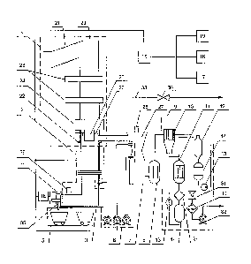
An overall waste recycling plant layout is represented in below Figure.
A radioactive waste recycling plant includes (1) a waste feed unit, a plasma
shaft-type furnace (2) with a melter (3) in the hearth and a slug discharge
unit (4)
which is connected to the receiving tank (5) for molten slug, an air supply
unit (6)
to supply air to the furnace (2) and to a pyrolysis gas combustion chamber
(7), an
evaporative heat exchanger (8) for sharp reduction of flue gas temperature,
gas
purification system (9) and fittings (not shown). A gas purification unit
includes a
sock-type filter (10), a heat exchanger (11), a scrubber (12), pumps (13) and
tanks
4
CA 3024945 2018-11-22
(14) for chemical agents and recycled products. A radioactive waste recycling
plant also includes a control module (15) and the below listed modules which
are
electrically connected to the control module (15): a control module (16) for
slug
discharge unit (4); an interior environment control module (17); an equipment
status control module (18) and a gas analytical module (19). The control
module
(15) is electrically connected to electric hardware of the following units: a
waste
feed unit (1), a plasma shaft-type furnace (2), a receiving tank for molten
slug (5),
an air supply unit (6) which supplies the air to the furnace (2) and to the
combustion chamber (7). A control module (16) for a slag discharge unit (4) is
io
electrically connected to the electric hardware of a slag discharge unit (4)
and
may include a digital video recorder, a temperature sensor for discharged
slag,
optical monitoring sensors (not shown in the figure) located inside the
receiving
tank for molten slag; a light alarm system with lighting columns and an
emergency button.
An interior environment control module (17) may include, at least,
temperature, pressure, flow and rarefication sensors (not shown in the
figure),
one sensor of each category.
An equipment status control module (18) may include, at least, one fittings
position transmitter and one pump control sensor (not shown in the figure).
A gas analytical module (19) includes concentration measuring sensors for
the following gas: oxygen, carbon monoxide, carbon dioxide, nitrogen oxide,
nitrogen dioxide, aggregate concentration of nitrogen oxide, sulfur dioxide
and
aggregate concentration of hydrocarbons (not shown in the figure). The
location
for installation of the gas analytical module (19) can be chosen to provide
for the
monitoring of pyrolysis gas composition in the gas stack between the plasma
shaft-type furnace (2) and the combustion chamber (7), and/or to provide for
the
monitoring of flue gases in the gas stack between the combustion chamber (7)
5
CA 3024945 2018-11-22
and the evaporative heat exchanger (8), and/or at the outlet of the recycling
plant.
A control module (15) is equipped with a data storage device and a data
output module in a form of a display, either a PC and/or a controller can be
used
as a control module (15). Inputs of the control module (15) are electrically
connected to the outputs (16) of the slug discharge (4) control module,
interior
environment control module (17), equipment status control module (18), and to
gas analytical module (19). Wherein the outputs of the control module (15) are
electrically connected with the electric hardware inputs of the waste feed
unit (1),
a plasma shaft-type furnace (2), a receiving tank (5) for molten slug, an air
supply
unit (6) delivering air to the furnace (2) and to the pyrolysis gas combustion
chamber (7).
A waste feed unit (1) may be equipped with a feed tank (20) and a feed
conveyor belt (21). The feed tank (20) may be equipped with, at least, one
proximity sensor (22) and, at least, two airtight sliding shutters (23), a
thermal
screen (24) and a feed spout (25). A plasm shaft-type furnace (2) may be
equipped with centrifugal jet nozzles (26) which are part of the emergency
spray
system and are installed in the upper part of the furnace.
The pyrolysis gas combustion chamber (7) may be equipped with a pre-
zo chamber (27) and a plasma generator (28) located in the top cover of pre-
chamber (27).
For more efficient combustion of pyrolysis gas the combustion chamber (7)
can be additionally equipped with an air supply unit (6). At this point the
air inlet
from the air supply unit (6) can be made at the same level with the pyrolysis
gas
inlet in the pre-chamber (27), and an additional air inlet from the air supply
unit
(6) can be located in the upper part of the base volume of the combustion
chamber (7). An air inlet from the air supply unit (6) to the plasma shaft-
type
furnace (2) is located in the bottom of the furnace,
6
CA 3024945 2018-11-22
A gas purification unit (9) can be additionally equipped with a separator
filter
(29) and, at least, one fine filter (30), and gas mixers (31) and exhaust fans
(32).
The plasma shaft-type furnace (2) and pyrolysis gas combustion chamber (7)
are equipped with a gas discharge duct (33) with emergency gas discharge
valves
s (34) and an emergency system of absorption purification.
The slug discharge unit (4) may include a discharge block (35) with a central
hole and a stopper.
A plasma shaft-type furnace (2) has a split design and is equipped with, at
least, one plasma generator (36) (80-170 kWt), moreover, the furnace melter
(3)
can be designed to enable its relocation if necessary, for example, it can be
placed
on a portable trolley. Moreover, the connection section between the slug
discharge unit (4) and the receiving tank (5) for molten slag also has a split
design.
A waste feed unit (1) may be equipped with a hopper to supply liquid
flammable radioactive waste to the plasma shaft-type furnace (2).
The air supply unit (6) supplying air to the furnace (2) and to the combustion
chamber (7) includes blow fans.
The recycling plant functions as follows: Solid radioactive waste packed in
craft bags are sent to the waste feed unit (1) where the operating personnel
in
consecutive stages put these bags onto the conveyor (21) to be further
delivered
to the feed tank (20). The control module (15) sends commands to the feed unit
(1) which loads the portions of packed radioactive waste into the furnace (2).
The
plasma shaft-type furnace (2) includes all stages of conversion for
radioactive
waste: drying, pyrolysis, oxidation of coking residues and slug melting. The
result
of recycling process are the molten slug and pyrolysis gas.
The temperature at all stages of waste conversion is controlled with the
control module (15). The blast air is supplied through the inlets of the air
supply
unit (6) which supplies the air to the furnace (2) and to the combustion
chamber
(7), the direction of blast air flow can be regulated by means of flaps. The
molten
7
CA 3024945 2018-11-22
slug is accumulated in the melter (3). The heating of the meter is provided
with,
at least, one plasma generator (36) with rated power of 80-170 kWt. From the
melter (3) the molten slug passes through the slug discharge unit (4) and is
fed to
the airtight receiving tank (5) for molten slug. The slug discharge unit (4)
is
s controlled by the slug discharge control module (16) which, in turn, is
controlled
by the control module (15). The molten slug is collected in metal containers
with
further holdup and cooling. Containers with molten slug are removed from the
receiving tank (5) and by means of a manipulator are loaded into a non-
returnable shielding container. All components of slug discharge unit (4) are
1.0 controlled by means of the control module (15).
Pyrolysis gas generated inside the shaft-type furnace (2) is fed to the
combustion chamber (7). The source of heat in the combustion chamber (7) is a
plasma generator (28). At a start-up stage two fuel supply nozzles (not shown
in
the figure) are used together with the plasma generator (28) to speed up the
1.5 heating of the pyrolysis gas combustion chamber (7) and suppress the
nitrogen
oxides which are generated as a result of operation of, at least, one plasma
generator (28). Functioning of fuel supply nozzles is supported with a diesel
supply system and a compressed air supply system.
The blast air is supplied to the pre-chamber (27) through the air supply unit
20 (6) inlets located in the upper and lower part of the combustion chamber
(7). Flue
gases heated in the combustion chamber (7) up to the temperature of +1200 -
1350 C are fed to the evaporative heat exchanger (8) where their temperature
is
sharply reduced up to +200 - 250 C. Cooling is ensured by means of complete
evaporation of water sprayed by pneumatic nozzles which are located in the
25 upper part of the evaporative heat exchanger (8). After the evaporative
heat
exchanger (8) the flue gases are delivered to the sock-type filter (10) where
most
of solid aerosol particles (dust) are captured. Flue gases purified in the
sock-type
8
CA 3024945 2018-11-22
filter (10) are supplied to the scrubber (12) where the downstream gas flow is
intensively sprayed with 4% alkaline solution.
In the scrubber (12) the flue gases are cooled up to 50 5 C and additionally
purified from acid gases and aerosols. After the scrubber (12) the flue gases
are
cooled up to 25 - 35 C in the tube side of the heat exchanger (11). In the
separator filter (29) cooled flue gases are separated from condensed moisture.
In
the gas mixers (31) the flue gases are heated and mixed with hot air, then
flue
gases pass fine filtration stage (30) and with exhaust fans they are directed
to a
ventilation stack.
i.o Gas
analytical modules (19) provide for the control over the condition of
interior environment, in particular, they allow for assessment of
concentration
and identification of gases generated as a result of waste recycling process.
Gal
analytical modules (19) are stationary continuously-operated plants used for
measuring concentration of the following gases: 02 (oxygen), CO (carbon
oxide),
3.5 CO2 (carbon
dioxide), NO (nitrogen oxide), NO2 (nitrogen dioxide), NO (aggregate
concentration of nitrogen oxides), SO2 (sulfur dioxide) 14 CH (aggregate
concentration of hydrocarbons). For measurement of CO, CO2, CH4 and 502
concentration an infrared absorption method is used, for NO, NO2 and NO -
measurement a chemiluminescent method is used, for measurement of CH
20 concentration a flame ionization method is used. Sampling method can be
described as forced sampling and it involves using a flow booster. A sampling
system provides for the filtration of the sample of mechanical impurities,
removal
of water vapors (for CO, CO2, SO2, CH 4 and 02 measurement), delivering the
sample to the measurement channel free from condensed water vapors,
25 delivering
the sample to CH measurement channel at a temperature of (190 10)
C.
Control and monitoring of the plant operation is provided with the control
module (15) which is connected with the interior environment control module
9
CA 3024945 2018-11-22
(17), which, in turn, is connected with the interior environment sensors (not
shown in the figure). Information about the condition of the interior
environment
is displayed on the screen of the interior environment control module (17).
Functioning of the equipment status control module (18) depends on the
information sent by the interior environment control module (17) to the
control
module (15), which, in accordance with integrated algorithms, generates
command electric signals forwarded to the equipment status control module (18)
Further on the equipment status control module (18), in accordance with its
integrated algorithms, generates a corresponding control signal for the
purpose
to influence the operation of the respective equipment. When the necessary
parameters of the interior environment are reached, the interior environment
control sensors acquire this information and forward it to the interior
environment control module (17). After that the interior environment control
module (17) registers the information about the fact that the necessary
parameters of the interior environment have been reached, and sends a
respective signal to the control module (15) The control module (15) upon
receipt
of this signal sends a command to the equipment status control module (18) to
cease its influence to the equipment.
Utilization of the alleged invention allows to provide a flexible operational
mode for the radioactive waste recycling plant.
Date Recue/Date Received 2020-09-22