Note : Les descriptions sont présentées dans la langue officielle dans laquelle elles ont été soumises.
CUPS AND CONTAINERS WITH A LIVING HINGE AND SLEEVES
[0001] A portion of the disclosure of this patent document contains
material which is subject
to copyright protection. The copyright owner has no objection to the facsimile
reproduction by
anyone of the patent document or the patent disclosure, as it appears in the
Patent and Trademark
Office patent file or records, but otherwise reserves all copyright rights
whatsoever.
CROSS-REFERENCES TO RELATED APPLICATIONS
[0002] This patent application is related to design patent applications for
Cups And
Containers With A Living Hinge And A Lid With A Dual Seal filed [Date],
Application No.
[Serial No.] and A Cup With a Living Hinge And An Attached Lid Having An Outer
Lip And
An Inner Dual Seal, filed [Date], Application No. [Serial No.] Each of those
applications is
incorporated here by this reference.
TECHNICAL FIELD
[0003] This invention relates to one-piece, easily recyclable, sealable,
non-leaking cups and
containers for holding hot or cold liquid or food with a receptacle portion
and a lid attached to
the receptacle with a living hinge. The cups and containers for hot liquid and
food may include
built-in insulation ribs or an injection molded sleeve for sliding over the
cups to insulate or
protect a user's hand from the heat of the liquid in the cup. The cups and
containers are
preferably made of a recyclable resin or polypropylene and are manufactured in
a quick and
efficient manner.
BACKGROUND ART
[0004] There are a number of prior art references in this field, including
U.S. Patent Nos.
3,373,896; 4,076,123; 4,257,526; 4,640,435; 5,270,011; 5,312,011; 5,820,016;
6,955,289;
CA 3025242 2018-11-23
8,100,289; 8,336,732; 8,701,887; 8,701,914; D642,863; D642,862; D642,864;
D683,186;; and
U.S. Published Application Nos. 2017/0096281 and 2012/0024877.
[0005] Each of these patents or published applications has one or more
deficiencies such as
collapsing when full, complicated for a user or complicated to manufacture,
multi-stream
recycling requirements, leaking, slow and inefficient manufacturing processes,
expensive
manufacturing processes, or bulky and not portable in large quantities. These
shortcomings
necessitate the need for one-piece, recyclable, sealable, non-leaking cups and
containers for
holding hot or cold liquid or food with a receptacle portion and a lid
attached to the receptacle
with a living hinge, a dual seal, and a fluid diverter as described in this
invention, and an
injection molded sleeve for sliding over the cup or container or built-in
insulation ribbing.
DISCLOSURE OF INVENTION
[0006] The present invention is a substantial improvement in utility and
functionality from
standard cup and lid combinations and overcomes the deficiencies in the art by
achieving one-
piece, totally recyclable, sealable, non-leaking cups and containers for
holding hot or cold liquid
or food with a receptacle portion and a lid attached to the receptacle with a
living hinge. The
inventive cups and containers for holding hot liquid may have a built-in
sleeve with a raised
surface that insulates the cup but does not interfere with stacking or the
efficient manufacturing
process. The build-in sleeve may be in the form of a film or repeating
vertical ribs that raise up
from the outer surface of the cups or containers. Also contemplated is an
injection molded sleeve
that fits over the receptacle portion of the cup for insulating the contents
or protecting a user's
hands from the heat of the material inside the cup.
[0007] The cups and containers are made by injection molding in an
efficient manner using
molds that can manufacture approximately 20 cups every 8 seconds. The material
used for the
2
CA 3025242 2018-11-23
inventive cups and containers, the claimed shapes and features of the cups and
containers, the
material of the mold, and the properties of the molding machine have all been
taken into account
in designing the embodiments disclosed and claimed herein as each unique
feature has been
carefully designed to facilitate the injection molding process. Because of the
unique features, the
process is efficient, high output, and provides a minimal impact on the
injection molding
machine to ensure longevity of the mold resulting in a highly economical
manufacturing process
that produces virtually leak free sealing cups and containers that are easily
stacked, shipped,
stored, and used.
[0008] Here, the injection molding operation creates all three parts, lid,
hinge, and lower
receptacle portion at one time as a single piece. The manufacturing components
are controlled
electronically resulting in an efficient manner of production and a decrease
in the amount of
spillage from the cups or containers, if any, by creating accurate
measurements and output of the
upper, inner dual seal in the receptacle portion, in the living hinge, on the
edge of the lid, and on
the contouring of the top of the lid. The manufacturing of the inventive cups,
containers, and
sleeves undercuts the cost of manufacturing paper cups, containers, and
sleeves significantly.
Further, the inventive design of the hinge is structured such that the mold
used to make the cups
and containers does not wear out. Specifically, the hinge radius is designed
for mold flexibility
and ejection requiring less ejection pressure.
[0009] Also, the design of the inventive cups, containers, and sleeves has
been carefully
honed to the presently claimed invention such that manufacturing time per unit
is significantly
reduced to less than 10 seconds per cup, container, or sleeve. This makes the
inventive products
commercially feasible and competitive pricewise with existing processes of
paper cups with a
poly lining or polystyrene foam cups, which are highly polluting to the
environment as nearly
3
CA 3025242 2018-11-23
600 billion foam and paper cups enter the waste stream annually according to
the International
Coffee Organization. To date, prior art foam and paper cups frequently end up
in the landfill or
in the ocean as plastic pollution.
[0010] In particular, the inventive designs put less pressure on the costly
manufacturing
molds providing longevity of approximately 15-20 years of use on the same
machine, and allow
for quick compression and turn-around time. This results in increased savings
as molds may cost
over hundreds of thousands of dollars and more per machine.
[0011] By contrast, the prior art molded cups with a lid attached had a
manufacturing time of
over a minute per cup, container, or sleeve and did not function as well as
the inventive designs.
For example, the prior art designs of a cup with a built in lid were unstable,
easily fell over or
collapsed when liquid was inside, the seal created between the lid and the
lower receptacle
leaked and did not stabilize the structure because of the lack of a dual seal
or fluid diverting
structure, and it was difficult to commercially manufacture them. These
inefficient designs
caused increase friction on the molds causing the molds to wear out quickly,
for example, after 5
years of use, thereby further decreasing the profitability of the designs.
[0012] Accordingly, the inventive embodiments disclosed provide a
substantial improvement
over prior patents of a cup with a built in lid as to function, leak proofing
seal, and commercial
manufacturing feasibility.
[0013] The inventive cup is molded and totally sealable and capable of
holding liquid or food
without leaking. The cup comprises a lower, receptacle portion having a base,
an open top, and
side walls in between the base and the open top, the base having a smaller
diameter than the top,
the side walls forming a cylinder from the base to the open top and creating
an inner and outer
portion of the cup, the open top having an upper edge defining the outermost
circumference of
4
CA 3025242 2018-11-23
the open top and a living hinge with a flexible radius and an indentation that
runs the full
circumference of the inner portion of the cup below the upper edge; the living
hinge molded in
the upper edge of the open top attached to the lower receptacle portion and a
lid, the living hinge
allowing the lid to flex over the open top wherein the lid securably fits into
the indentation that
runs the full circumference of the inner portion of the cup; the lid having a
top surface and a
bottom surface of a size and shape to securably fit into the inner
circumference of the open top of
the cup, the top surface of the lid being sloped downward from the outermost
circumference of
the open top to the center of the lid, the circumference around the bottom
surface of the lid
having a lip extending down from the circumference of the lid, the lip
creating a dual seal
structure having a bottom edge that fits in the indentation that runs the full
circumference of the
inner portion of the cup and a top edge that is the same size and shape as the
inner circumference
of the upper edge of the top, the top edge having one or more 1-shaped tabs
extending from the
top edge up and over the upper edge of the cup; wherein the living hinge
permits the lid to bend
along a line of the hinge to flexibly secure the lid to the cup and prevent
leakage of the material
held therein.
[0014] The
internal bi-directional sealing surfaces on the lip of the lid extending down
from
the circumference of the lid exhibit a radius male/female horizontal seal
combined with a flat
vertical seal of some length that is injection molded and which can be adapted
to all other forms
of molding including vacuum or thermal-forming via dual "skirting" features.
Accordingly, the
structure provides for a secure seal to virtually prevent all fluid leakage
when the lid is locked
properly within the indentation running the circumference of the inner portion
of the cup. Also,
the fluid diverter on the top of the lid ensures that all fluids run away from
the seal and towards
the top center of the lid. This prevents puddling at the lid-wall
intersection. The fluid diverter is
CA 3025242 2018-11-23
positioned throughout the entire top circumference of the lid, including on
the living hinge to
ensure the most effective seal and flow of liquids away from the edge. This
helps when opening
the cups too to prevent liquid from dripping on the user unnecessarily. The bi-
directional seal is
included in all cups and containers.
[0015] In
some embodiments, the lid has a small opening opposite the living hinge to
allow
liquid to pass through. An individual drinking from the cup could sip liquid
through the small
opening. In addition, in some embodiments with this small drinking hole
opening, the lid has a
breathe hole approximately 1-2 mm in diameter next to the living hinge to
allow for the smooth
flow of liquid from the cup and eliminate the suction that would keep the
liquid from coming out
of the drinking hole. Alternatively, the lid has a circular opening in the
center capable of
receiving a straw. Also, the cups can be easily stacked because of the inner
concentric circular
material on the inside of the cup just above the base. This inner portion of
the cup above the
base has a concentrically molded lip extending the circumference of the inner
portion of the cup
on the sidewall just above the base. This concentrically molded lip allows
cups to be stacked
together and easily removed because the base of each cup maintains a distance
from a second
cup and does not cause the cups to stick together.
[0016] The
living hinge of the cup is thin and flexible with a flexible radius, having
the same
thickness as the rest of the cup and made from the same material as the lower
portion of the cup
and the lid, the flexible radius allowing for the lid to bend along the line
of the hinge and
securely fit within the top inside of the cup. The flexible radius is
positioned in a break in the
top circumference of the cup, the break in the circumference having two
arcuate edges on either
side of the living hinge extending from the flexible radius of the living
hinge up to the upper
edge.
6
CA 3025242 2018-11-23
[0017] The arcuate edges ensure that there is no wear and tear on the
living hinge, provide
minimal friction, and allow for a smooth opening and closing movement. The top
of the living
hinge on the top of the lid of the cup is also curved, maintaining the same
curve as the inner
circumference of the cup. The curved shape of this portion of the hinge
ensures that any
additional liquid material on the top of the lid is directed downward and away
from the seal.
Furthermore, the overall shape of the living hinge and the arcuate edges in
the break in the
circumference ensure a secure seal between the lid and the bottom portion of
the cup. In
addition, the shape allows efficient molding and removal of the cup from the
mold in the
manufacture of the cup such that the molds are not worn unnecessarily and
manufacturing can be
done quickly and faster than prior molding processes.
[0018] The inventive containers may be round in shape similar to the cups
or may be
rectangular or square to accommodate food articles. All of the containers have
the same living
hinge and are made of the same material as the cups. They are molded and
totally sealable and
capable of holding liquid or food without leaking. The containers comprises a
lower, receptacle
portion having a base, an open top, and side walls in between the base and the
open top, the base
being round, substantially rectangular or square, and having a smaller area at
the bottom than the
top, the side walls forming a cylinder if the container base is round, or side
walls in a rectangular
or square shape if the base is rectangular or square, respectively, all side
walls emanating from
the base to the open top and creating an inner and outer portion of the
container, the open top
having an upper edge defining the outermost circumference of the open top and
a living hinge
with a flexible radius and an indentation that runs the full circumference of
the inner portion of
the container below the upper edge; the living hinge molded in the upper edge
of the open top
attached to the lower receptacle portion and a lid, the living hinge allowing
the lid to flex over
7
CA 3025242 2018-11-23
the open top wherein the lid securably fits into the indentation that runs the
full circumference of
the inner portion of the container; the lid having a top surface and a bottom
surface of a size and
shape to securably fit into the inner circumference of the open top of the
container, the top
surface of the lid being sloped downward from the outermost circumference of
the open top to
the center of the lid, the circumference around the bottom surface of the lid
having a lip
extending down from the circumference of the lid, the lip creating a dual seal
structure having a
bottom edge that fits in the indentation that runs the full circumference of
the inner portion of the
container and a top edge that is the same size and shape as the inner
circumference of the upper
edge of the top, the top edge having one or more I-shaped tabs extending from
the top edge up
and over the upper edge of the cup; wherein the living hinge permits the lid
to bend along a line
of the hinge to flexibly secure the lid to the container and prevent leakage
of the material held
therein.
[0019] The containers may have an opening in the lid to let steam escape or
to pour liquid
out.
[0020] The inventive sleeves are open on the inside, round in shape, and
the inner diameter
of the sleeve is wider at the top than at the bottom so as to create a snug
fit over the lower
receptacle portion of the inventive cups upon application. They are rigid and
collapsible with
living hinges on either side of the sleeve. They do not have overlapping sides
such that the
thickness is consistent throughout. The sleeve is created by an injection
molded manufacturing
process out of the same resin as the inventive cups and containers. It may
vary in width size in
order to accommodate cups of different sizes, e.g., cups capable of holding
approximately 2 to
40 ounces, although the width may be constant and of a size and shape that
could accommodate
8
CA 3025242 2018-11-23
cups of all sizes capable of holding approximately 2 to 40 ounces of liquid.
For example the
diameter of the sleeves may be between 2 and 8 cm, preferably between 3 and 6
cm.
[0021] The length of the inventive sleeves is adapted to provide enough
coverage over a cup
so that a user holding the cup or container would be protected from a cup or
container holding
hot liquids or foods. For example, the length of the sleeves may be between 2
to 8 cm,
preferably between 2 to 5 cm.
[0022] .. The material used to manufacture the cups, containers, and sleeves
is preferably a
resin, polypropylene, or other similar recyclable and moldable material.
Alternative materials
may include a bioresin that is biodegradable and compostable creating a
similar, singular stream
of recycling as the use of the resin polypropylene. Because the inventive
embodiments use a
single material for the cup, lid, sleeve, and label, they are totally
recyclable and can be reground
into a usable resin straight from a recycling bin.
[0023] Further, an advantage of the cups and containers being the same
material as the
sleeves is that the inventive items create a single stream of recycling
because there are no
separation requirements. The cup, lid, sleeve, and any printed labels on the
cups or containers
are made of the same single resin or bioresin and are truly recyclable or
degradable.
[0024] By contrast, existing prior art cups and lids are comprised of
layers of one or more
materials or are a combination of paper and plastic that complicate the
recycling process. In
order to recycle cups and containers that are comprised of layers, they must
be stripped into their
component parts in order to recycle them. For example, Tetra"' packs that hold
many food and
liquid items are lined with a material that must be stripped from the outer
material before
recycling. Paper cups used at coffee shops with a high volume of consumers are
coated with a
thin plastic lining to prevent leaks. These are more challenging to recycle
because the plastic
9
CA 3025242 2018-11-23
isn't easy to separate from the paper. Currently, there are very few cities
that have the proper
infrastructure in place to process such "layered" or lined cups and
containers. While New York,
Seattle, and Washington DC are three of the cities that can tackle this
complex process, cities
without this capability end up putting the prior art cups and containers in a
landfill. Also, it is
much less expensive for large coffee shops to send their lined paper cup waste
and plastic lids to
a landfill than to locate outlets to process the cups in order to compost and
recycle them.
[0025] Further, paper cups and containers contaminated with grease or food
residue, which
commonly occurs when containers hold food or when cups or containers are
placed in a
recycling bin with other greasy materials, cannot be recycled at all. In sum,
recyclable and
compostable packaging is only beneficial if it ends up at a waste facility
that can process it.
Many compostable cups will not breakdown in a backyard composter because they
do not get hot
enough, or even in a landfill where waste decomposes through an anaerobic
process producing
methane, a greenhouse gas. And, compostable cups can be contaminants at a
recycling facility.
[0026] Here, the inventive cups, containers, sleeves, and label are made in
the same resin and
can be discarded without the need for the separation by the user or processor.
This resolves the
conflicts and confusion in the recycling industry where single-stream bins now
include paper
bonded with polyactic acid linings that can only be removed or separated in
the few cities with
the expensive infrastructure to do so. These along with the mixed plastic
resin cups that
contaminate recycling grounds if not separated are among the vast majority of
the 600 billion
paper and plastic cups produced annually that end up in landfills every year.
[0027] More stringent measures to reduce this waste are in the works as
many cities and
municipalities are considering a tax on single use prior art paper cups or
banning them outright.
CA 3025242 2018-11-23
The inventive cups, containers, sleeves, and labels resolve this problem in
the art as they are
multiple use, reusable, and totally recyclable or biodegradable.
[0028] An alternative method of production of the cups, containers, and
sleeves may include
3-D printing, thermoforming, or vacuum thermoforming.
BRIEF DESCRIPTION OF DRAWINGS
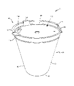
[0029] Figure 1 is a perspective view of a cup with a living hinge and a
lid having an inner
dual seal with an indented lid;
[0030] Figure 2 is a right side view thereof;
[0031] Figure 3 is a front view thereof;
[0032] Figure 4 is a top view thereof;
[0033] Figure 5 is a perspective view of a cup with a living hinge and a
lid having an inner
dual seal with a bubble shaped lid;
[0034] Figure 6 is a side view thereof;
[0035] Figure 7 is a front view thereof;
[0036] Figure 8 is a top view thereof;
[0037] Figure 9 is a perspective view of a round-bottomed container with a
living hinge
and a lid having an inner dual seal with an indented lid;
[0038] Figure 10 is a side view thereof;
[0039] Figure 11 is a front view thereof;
[0040] Figure 12 is a top view thereof;
[0041] Figure 13 is a perspective view of a substantially rectangular-
bottomed container with
a living hinge and a lid having an inner dual seal with an indented lid;
[0042] Figure 14 is a side view thereof;
11
CA 3025242 2018-11-23
[0043] Figure 15 is a front view thereof;
[0044] Figure 16 is a top view thereof;
[0045] Figure 17 is a perspective view of a cup with a living hinge and a
lid having an inner
dual seal with an indented lid with the lid in an open position
[0046] Figure 18 is a side view thereof;
[0047] Figure 19 is a front view thereof;
[0048] Figure 20 is a top view thereof;
[0049] Figure 21 is a perspective view of a cup with a living hinge and a
lid having an inner
dual seal with a bubble shaped lid with the lid in an open position;
[0050] Figure 22 is a side view thereof;
[0051] Figure 23 is a front view thereof;
[0052] Figure 24 is a top view thereof;
[0053] Figure 25 is a perspective view of a round-bottomed container with a
living hinge
and a lid having an inner dual seal with an indented lid with the lid in an
open position;
[0054] Figure 26 is a side view thereof;
[0055] Figure 27 is a front view thereof;
[0056] Figure 28 is a top view thereof;
[0057] Figure 29 is a perspective view of a substantially rectangular-
bottomed container with
a living hinge and a lid having an inner dual seal with an indented lid with
the lid in an open
position;
[0058] Figure 30 is a side view thereof;
[0059] Figure 31 is a front view thereof;
[0060] Figure 32 is a top view thereof;
12
CA 3025242 2018-11-23
[0061] Figure 33 is a perspective view of the inventive cups with a living
hinge and an inner
dual seal stacked with the lid in the open position
[0062] Figure 34 is a side, blown-up view of the inner dual seal on the lid
in a closed
position;
[0063] Figure 35 is a perspective view of the inner dual seal on the lid in
an open position;
[0064] Figure 36 is a second perspective view of the inner dual seal on the
lid in an open
position;
[0065] Figure 37 is a blown-up perspective view of the inner dual seal on
the lid in a closed
position; and
[0066] Figure 38 is a blown-up perspective view of the living hinge.
[0067] Figure 39 is a perspective view of the cup with insulated ribbing
wrapping the outside
of the cup.
BEST MODE FOR CARRYING OUT THE INVENTION
[0068] The detailed description set forth below in connection with the
appended drawings is
intended as a description of presently-preferred embodiments of the invention
and is not intended
to represent the only forms in which the present invention may be constructed
or utilized. The
description sets forth the functions and the sequence of steps for
constructing and operating the
invention in connection with the illustrated embodiments. However, it is to be
understood that
the same or equivalent functions and sequences may be accomplished by
different embodiments
that are also intended to be encompassed within the spirit and scope of the
invention.
[0069] Figure 1 is a perspective view of a cup with a living hinge and a
lid having an inner
dual seal with an indented lid. The molded, sealable cup for holding liquid or
food comprising
has a lower, receptacle portion 20 having a base 30, an open top 40, and side
walls 50 in
13
CA 3025242 2018-11-23
between the base and the open top, the base having a smaller diameter than the
top, the side walls
forming a cylinder from the base to the open top and creating an inner and
outer portion of the
cup, the open top having an upper edge 60 defining the outermost circumference
of the open top
and a living hinge 70 with a flexible radius 80 and an indentation 90 that
runs the full
circumference of the inner portion of the cup below the upper edge. The living
hinge 70 is
molded in the upper edge of the open top 60 attached to the lower receptacle
portion 20 and a lid
100, the living hinge 70 allowing the lid 100 to flex over the open top
wherein the lid 100
securably fits into the indentation 108 that runs the full circumference of
the inner portion of the
cup. The lid structure 100 has a top surface 102 and a bottom surface 104 of a
size and shape to
securably fit into the inner circumference of the open top of the cup 108, the
top surface of the
lid being sloped downward from the outermost circumference of the open top to
the center of the
lid 90, the circumference around the bottom surface of the lid having a lip
extending down from
the circumference of the lid 106, the lip 106 creating a dual seal structure
having a bottom edge
106 that fits in the indentation that runs the full circumference of the inner
portion of the cup 108
and a top edge that is the same size and shape as the inner circumference of
the upper edge of the
top, the top edge having one or more I-shaped tabs 120 extending from the top
edge up and over
the upper edge of the cup 10. The living hinge 70 of the present invention
permits the lid 100 to
bend along a line of the hinge to flexibly secure the lid 100 to the lower
portion of the cup 20 and
prevent leakage of the material held therein.
[0070] In addition, the indentation that runs the full circumference of the
inner portion of the
lid below the upper edge 90 directs fluid away from the seal and into the
center of the lid. and
[0071] wherein the dual seal ensures that the outer circumference of the
lid contacts the inner
circumference of the cup to ensure a secure seal. These internal bi-
directional sealing surfaces
14
CA 3025242 2018-11-23
exhibit a radius male/female horizontal seal combined with a flat vertical
seal of some length that
is injection molded and which can be adapted to all other forms of molding
including vacuum or
thermal-forming via dual "skirting" features. Also, the inner molded 360
degree stacking feature
can be located on the inner side of the circumference of the sidewall of the
cup 132. The
stacking feature 132 can add weight to the cup and improve anti-tipping
stability of the product
because it causes the inner circumference of the cup just above the base to be
a bit thicker than
the side walls of the cup. An alternative design of the stacking feature can
be raised concentric
circles be located at the bottom most inside base of the cup.
[0072] Also, the fluid diverter 90 on the top of the lid ensures that all
fluids run away from
the seal and towards the top center of the lid. This prevents puddling at the
lid-wall intersection.
This fluid diverter 90 is positioned around the entire circumference of the
top of the lid,
including the living hinge 70 area. The living hinge 70 is designed for mold
flexibility and
ejection requiring less ejection pressure.
[0073] The lid may have a small opening 130 opposite the living hinge to
allow liquid to
pass through and a small breathe hole adjacent to the living hinge to allow
for the smooth flow of
the liquid though the small opening when one is drinking. The small breathe
hold prevents the
suction of the liquid created when trying to drink the fluid out of the cup.
Also, the base of the
inner portion of the cup has a concentrically molded lip 132 extending the
circumference of the
inner portion of the cup on the sidewall just above the base wherein the
concentrically molded lip
132 allows cups to be stacked together and easily removed. In stacking the
cups, the base of a
second cup sits on top of the concentrically molded lip 132 of a first cup and
the living hinges
and lids line up. Multiple cups can be stacked upon one another and easily
separated as shown in
Figure 33. Disposable cups in the prior art may not have this feature
resulting in cups sticking
CA 3025242 2018-11-23
together when stacked and requiring complicated dexterity from a user to
separate the cups. By
contrast, the inventive cups may be selected from a stack by a user and easily
separated without
sticking due to the concentrically molded lip 132 allowing flight attendants,
coffee shop and
restaurant industry servers to quickly access a cup and assist a client.
[0074] In addition, the upper edge of the cup 60 has a break in the
circumference to
accommodate the living hinge 70, the break in the circumference having two
arcuate edges 72 on
either side of the living hinge extending from the flexible radius 80 of the
living hinge 70 up to
the upper edge 60.
[0075] The cup shown in Figure 1, along with all other embodiments of cups
and containers
disclosed herein may have a built-in insulation sleeve comprised of vertical
concentric ribs that
rise above the surface of the lower receptacle portion and insulate the cup or
container, but do
not interfere with stacking or manufacturing. The raised ribs are made of the
same material as
the cup.
[0076] The cup shown in Figure 1, along with all other embodiments of cups
and containers
disclosed herein may have a label wrapping around the outside of the cup or
container made of
the same material as the cup or container so nothing has to be peeled off or
changed prior to
placing the inventive cup or container into the recycling stream. The labels
may be clear,
colored, white and have a smooth texture or an "orange peel" slightly rough
texture. Product
names, pictures, and text may be added to the labels. Also, the labels can be
added during the
injection molding process so that manufacturing is not complicated by the
addition of the label.
[0077] Figure 2 is a right side view of the cup 10 with a living hinge 70
and a lid having an
inner dual seal when the lid is friction fit into the lower portion of the cup
20, and fit within the
inner indentation running the circumference of the inner portion of the cup,
the outer rib is
16
CA 3025242 2018-11-23
shown 110. The first component of the dual seal is the fit within the
indentation and the second
component of the dual seal is the friction fit of the upper edge of the bottom
portion of the lit
pushed into the interior of the cup. The lid can be easily removed and
inserted using one or more
tabs 120.
[0078] Figure 3 is a front view of the cup 10 with the lid in the closed
position showing
one or more tabs 120. Also, the outer exterior rib 110 of the inner dual seal
when the lid is
friction fit into the lower portion of the cup 20 is shown.
[0079] Figure 4 is a top view of the cup 10 with a living hinge 70 and the
flexible radius
80 showing the lid in the friction fit position The fluid diverter structure
90 is shown and as
noted herein is higher where the edge of the lid meets the inside of the cup
and angled down in
the direction of the center of the lid in order to divert fluid away from the
seal. One or more tabs
120 to assist opening and closing the lid are shown along with a small opening
130 through
which liquid inside the cup may pass or a straw may be inserted.
[0080] Figure 5 is a perspective view of a cup 140 with a living hinge 160
and a bubble or
dome shaped lid 150 having a dual seal, the inner workings, including the
bottom edge of the
bubble lid 194, the lip on the bottom edge of the bubble lid 196 that fits
into the indentation
running the circumference of the inner portion of the cup 198 of which are
shown in Figure 21,
and the outer portion of the dual seal structure 180 where the lip on the
bottom edge of the
bubble lid fits securely within is shown. This embodiment 140 has a lower,
receptacle portion
152 having a base 154, an open top156, and side walls 158 in between the base
154 and the open
top 156, the base 154 having a smaller diameter than the top 156, the side
walls 158 forming a
cylinder from the base 154 to the open top 156 and creating an inner and outer
portion of the cup,
17
CA 3025242 2018-11-23
the open top 156 having an upper edge 157 defining the outermost circumference
of the open top
156 and a living hinge 160 with a flexible radius.
[0081] The living hinge 160 molded in the upper edge 157 of the open top
156 attached to
the lower receptacle portion 152 and a bubble or dome shaped lid 150, the
living hinge 160
allowing the lid 150 to flex over the open top 156 wherein the lid 150
securably fits into the
indentation that runs the full circumference of the inner portion of the cup
198.
[0082] The lid 150 has a top surface 192 and a bottom edge 194 of a size
and shape to
securably fit into the inner circumference of the open top of the cup, the top
surface of the lid
192 having a bubble shape 150 rising from the outermost circumference of the
open top 156, the
circumference around the bottom surface of the lid 164 having a lip 196
extending down from
the circumference of the lid, the lip 196 creating a dual seal structure
having a bottom edge 196
that fits in the indentation that runs the full circumference of the inner
portion of the cup 198 and
a top edge 192 that is the same size and shape as the inner circumference of
the upper edge of the
top, the top edge 192 having one or more 1-shaped tabs extending from the top
edge up and over
the upper edge of the cup 157. As in the other embodiments, the living hinge
160 permits the lid
150 to bend along a line of the hinge to flexibly secure the lid 150 to the
lower receptacle portion
152 and prevent leakage of the material held therein.
[0083] The inside of the cup 140 may have an inner concentric circle 200 as
described in
embodiment 10 to enhance the ease of stacking, storing, and removing or
separating the cups
from one another.
[0084] Figure 6 is a side view of the cup 140 with a living hinge 160 and a
bubble or dome
shaped lid 150. The dome shaped lid 150 fits within the inside of the cup and
inside the upper
outer edge of the top of the cup 157. A tab 170 on the lid 150 assists in
opening and closing the
18
CA 3025242 2018-11-23
lid 150. The outer rib of the seal structure on the bottom portion of the cup
180 is shown. This
receives the lip on the bottom edge of the lid and another secure closure is
created at the juncture
of the bottom edge of the lid and the inside of the cup so that a dual seal is
created with the lip
and the juncture between the bottom edge of the lid and the inside of the cup.
[0085] Figure 7 is a front view of the cup 140 with a living hinge and a
bubble or dome
shaped lid 150 having an inner dual seal showing a tab 170, the upper edge of
the cup 157 within
which the dome shaped lit fits and the outer rib 180 of the inner indentation
of the lower
component of the inner dual seal.
[0086] Figure 8 is a top view of the cup 140 with a living hinge and a
bubble or dome shaped
lid 150 in the closed position showing the living hinge 160 a tab 170 and an
opening 190 in the
top of the lid for receiving a straw.
[0087] Figure 9 is a perspective view of a round-bottomed container 210
with a living
hinge and a lid having an inner dual seal with an indented lid. The molded,
sealable container
210 for holding liquid or food has a lower, receptacle portion 220 having a
base 230, an open top
240, and side walls 250 in between the base 230 and the open top 240, the base
230 having a
smaller area than the top 240, the side walls 250 extending from the base 230
to the open top 240
and creating an inner and outer portion of the container 210, the open top 240
having an upper
edge 260 defining the outermost circumference of the open top 250 and a living
hinge 270 with a
flexible radius 280 and an indentation that runs the full circumference of the
inner portion of the
container below the upper edge 308.
[0088] The living hinge 270 is molded in the upper edge 260 of the open top
240 attached to
the lower receptacle portion 220 and a lid 300, the living hinge 270 allowing
the lid 300 to flex
over the open top 240 wherein the lid 300 securably fits into the indentation
308 that runs the full
19
CA 3025242 2018-11-23
circumference of the inner portion of the container. The upper edge 260 of the
open top has
arcuate edges on either side of the living hinge 270 that allow for ease of
opening the lid 300,
provide less wear and tear on the lid 300 and lower receptacle portion 220
with repeated opening
and closing, and provide for ease of manufacturing and less impact on the
machines used to
manufacture the containers 210. Also, the arcuate edges, and shape of the
living hinge aid in
keeping the contents of the container within the container when the lid 300 is
opened and closed.
[0089] The lid 300 has a top surface 302 and a bottom surface 304 of a size
and shape to
securably fit into the inner circumference of the open top 240 of the
container, the top surface of
the lid 302 being sloped downward from the outermost circumference of the open
top to the
center of the lid 290. As shown in Figure 25 and 26, the circumference around
the bottom
surface of the lid 304 having a lip 306 extending down from the circumference
of the lid, the lip
304 creating a dual seal structure having a bottom edge that fits in the
indentation 308 that runs
the full circumference of the inner portion of the container and a top edge
302 that is the same
size and shape as the inner circumference of the upper edge of the top, the
top edge having one
or more 1-shaped tabs 320 extending from the top edge up and over the upper
edge of the
container 210. The outside of the indentation that receives the lip of the lid
is shown 310. This is
a portion of the inventive dual seal structure that ensures a secure fit of
the lid into the container
and prevents leakage, spillage, and helps to stabilize the cup.
[0090] Figure 10 is a side view of a round-bottomed container 210 with a
living hinge 270
and a lid with a tab 320 having an inner dual seal, an outside rib 310 of
which is shown.
[0091] Figure 11 is a front view of a round-bottomed container 210 with the
lid in the closed
position, a tab 320 and an inner dual seal, an outside rib of which is shown
310.
CA 3025242 2018-11-23
[0092] Figure 12 is a top view of a round-bottomed container 210 with the
lid in the closed
position with a living hinge 270, a flexible radius 280, and a fluid diverter
290 that runs the
entire circumference of the top edge of the lid at the juncture of the seal
between the cup and the
lid. A tab 320 on the lid is also shown.
[0093] Figure 13 is a perspective view of a substantially rectangular-
bottomed container 410
with a living hinge 470 and a lid 500 having an inner dual seal comprised
shown in detail in
Figures29 and 30 with an indentation or fluid diverter 490 on the top surface
of the lid 502 to
draw fluid away from the seal. The molded, sealable container 410 for holding
liquid or food has
a lower, receptacle portion 420 having a base 430, an open top 440, and side
walls 450 in
between the base 430 and the open top 440, the base 430 having a smaller area
than the top 440,
the side walls 450 extending from the base 430 to the open top 440 and
creating an inner and
outer portion of the container 410, the open top 440 having an upper edge 460
defining the
outermost circumference of the open top 450 and a living hinge 470 with a
flexible radius 480
and an indentation that runs the full circumference of the inner portion of
the container below the
upper edge 508 as shown in Figure 29.
[0094] The living hinge 470 is molded in the upper edge 460 of the open top
440 attached to
the lower receptacle portion 420 and a lid 500, the living hinge 470 allowing
the lid 500 to flex
over the open top 440 wherein the lid 500 securably fits into the indentation
508 that runs the full
circumference of the inner portion of the container. The upper edge 460 of the
open top has
arcuate edges on either side of the living hinge 470 that allow for ease of
opening the lid 500,
provide less wear and tear on the lid 500 and lower receptacle portion 420
with repeated opening
and closing, and provide for ease of manufacturing and less impact on the
machines used to
21
CA 3025242 2018-11-23
manufacture the containers 410. Also, the arcuate edges, and shape of the
living hinge aid in
keeping the contents of the container within the container when the lid 500 is
opened and closed.
[0095] The lid 500 has a top surface 502 and a bottom surface 504 of a size
and shape to
securably fit into the inner circumference of the open top 540 of the
container, the top surface of
the lid 502 being sloped downward from the outermost circumference of the open
top to the
center of the lid 490. As shown in Figures 29 and 30, the circumference around
the bottom
surface of the lid 504 having a lip 506 extending down from the circumference
of the lid, the lip
504 creating a dual seal structure having a bottom edge that fits in the
indentation 508 that runs
the full circumference of the inner portion of the container and a top edge
502 that is the same
size and shape as the inner circumference of the upper edge of the top, the
top edge having one
or more 1-shaped tabs 320 extending from the top edge up and over the upper
edge of the
container 410. The outside of the indentation that receives the lip of the lid
is shown 510. This is
a portion of the inventive dual seal structure that ensures a secure fit of
the lid into the container
and prevents leakage, spillage, and helps to stabilize the cup. The container
410 may also have
one or more tabs 520 to facilitate opening and closing.
[0096] Figure 14 is a side view of a substantially rectangular-bottomed
container 410 with a
living hinge 470 and a lid having an inner dual seal and a tab 520 to assist
opening and closing of
the lid. The lid fits inside the container as described herein and the outside
rib of one component
portion of the dual seal is shown 510.
[0097] Figure 15 is a front view of a substantially rectangular-bottomed
container 410
showing tabs 520 and the outside of the one component portion of the dual seal
510.
[0098] Figure 16 is a top view of a substantially rectangular-bottomed
container 410 with the
upper edge of the container 460 having a living hinge 470, and a lid 500 in
the closed position
22
CA 3025242 2018-11-23
having a fluid diverter in a substantially rectangular shape following the
overall shape of the
container 490 that is diagonally positioned to divert fluid away from the
seal. The top also
shows a tab 520.
[0099] Figure 17 is a perspective view of a cup 10 with a living hinge 70
and a lid 100 in the
open position having an inner dual seal comprised of the friction fit of the
edge of the lid and the
lip 106 on the bottom edge of the lid 104 that fits within the indentation
running the
circumference of the inner portion of the cup 108. The edge of the lid is
approximately 1-14mm,
preferably around 2-6mm in length. The top of the lid is 102 has an I-shaped
tab 120 to ease
opening and closing. Also, the outside of one component of the dual seal
structure 110 is shown
as a rib running the full outer circumference of the lower portion of the cup.
[00100] Figure 18 is a side view of a cup 10 with a living hinge 70 and a lid
in the open
position having an inner dual seal, a first component of which is the bottom
lip 106 that friction
fits into the interior of the cup and the outer rib of this click-fit lip into
the interior indentation.
The second component part of the dual seal is the top friction fit portion of
the lid when the lip
106 is pushed into place and is created because of the size of the edge of the
lid next to the lip
106 that is approximately 2-6 mm in length. The size of the edge of the lid
will vary depending
on how many ounces the cup or containers hold, but in any event the size of
the edge will
accommodate and achieve the dual seal structure described herein.
[00101] Figure 19 is a front view of a cup 10 with the lid in the open
position.
[00102] Figure 20 is a top view of a cup 10 with a living hinge and a lid
in the open position
having an inner dual seal, the lower lip edge of which is shown as 106, the
bottom of the lid 104,
and a small opening in the lid 130 along with an 1-shaped tab on the lid are
shown. Also, the
inner concentric circle 132 is shown just above the inside base of the cup.
This is a raised area
23
CA 3025242 2018-11-23
extending approximately 0.5cm to 1.5cm up from the inside base of the cup. It
runs the entire
circumference of the inside just above the base and ensures easy cup stacking,
spacing,
manufacture, and removal, and helps to stabilize the cup so that it stands
upright when the lid is
open. This feature is in all of the inventive cups and containers disclosed
herein.
[00103] Figure 21 is a perspective view of a cup 140 with a living hinge 160
and a bubble
shaped lid 150 having a top 192 and a bottom 194 with a lip 196 on the bottom
edge of the lid
194 that fits into the indentation 198 running the circumference of the inner
portion of the cup
156. The lid 150 has a tab 170 to ease opening and closing and fits within the
upper edge of the
cup 157 and nestles inside into the indentation in order to ensure a secure
fit between the lid 150
and the bottom portion of the cup 158. Within the cup and just above the base
152, there is an
inner concentric circle (not shown) to aid stacking, spacing, manufacture,
removal, and
stabilization of the cup.
[00104] Figure 22 is a front view of a cup 140 with a living hinge 160 and a
bubble shaped
lid wherein the lip 196 and the lid fit within the lower receptacle portion of
the cup and the outer
portion of the lower component of the dual seal structure is shown 180.
[00105] Figure 23 is a front view of a cup 140 with a living hinge 160 and a
bubble shaped
lid with the lid in the open position wherein the lid, when moved at the
living hinge fits within
the lower receptacle portion of the cup and the outer portion of the lower
component of the dual
seal structure is shown 180.
[00106] Figure 24 is a top view of a cup with a living hinge and a bubble
shaped lid in the
open position. The inner concentric circle 200 is shown positioned just above
the base.
[00107] Figure 25 is a perspective view of a round-bottomed container 210 with
a living
hinge and a lid in the open position wherein the lip 306 on the bottom side of
the lid 304 fits
24
CA 3025242 2018-11-23
within the indentation on the inside of the container 308, the outside of the
indentation is shown,
310, and the top of the lid 302, when pressed down into the container creates
a dual seal with the
lip 306 and the friction fit of the bottom edge of the lid with the interior
portion of the container.
[00108] Figure 26 is a side view of a round-bottomed container 210 with a
living hinge and a
lid in the open position. The lip 306 on the bottom side of the lid is shown
as well as the outside
of the indentation 310.
[00109] Figure 27 is a front view of a round-bottomed container 210 with a
living hinge and
a lid in the open position, and the outside of the indentation 310 is shown.
[00110] Figure 28 is a top view of a round-bottomed container 210 with a
living hinge with
the lid in the open position. The inner concentric circle as described herein
330 is also shown.
[00111] Figure 29 is a perspective view of a substantially rectangular-
bottomed container 410
with a living hinge and a lid having an inner dual seal. The bottom edge of
the lid 504 with lip
506 that fits within the inner indentation 508 that runs the entire inner
circumference of the
container and the outer rib 510 of the inner indentation. When the top of the
lid 502 is pressed
into the container, a dual seal is created.
[00112] Figure 30 is a side view of a substantially rectangular-bottomed
container 210 with a
living hinge with the lid in the open position showing the lip 506 and the
substantial bottom edge
of the lid that friction fits into the container and the outside rib of the
bottom portion of the dual
seal 510 is shown.
[00113]
Figure 31 is a front view of a substantially rectangular-bottomed container
210 with
a living hinge with the lid in the open position and the outside rib of the
bottom portion of the
dual seal 510.
CA 3025242 2018-11-23
[00114] Figure 32 is a top view of a substantially rectangular-bottomed
container 410 with a
living hinge and a lid having an inner dual seal with an indented lid with the
lid in an open
position. As shown, the inner concentric substantially rectangular shaped
structure 530 appears
just above the base of the container and follows the contour of the inside
shape of the container.
This portion of the container has a slightly smaller diameter that the rest of
the inside of the
container and is about 0.5 to 1.5 cm high from the base of the inside of the
container. The
structure aids in stacking the containers and provides ease of removal because
the containers do
not stick together.
[00115] Figure 33 is a perspective view of the inventive cups 20 with a living
hinge and an
inner dual seal stacked with the lid in the open position. All cups and
containers stack in this
fashion. The dashed lines show the interior bottoms of each of the cups and
where they sit as a
result of the inner concentric circle 132 in the bottom portion of each cup.
[00116] Figure 34 is a side, blown-up view of the inner dual seal created by a
lip 106 on the
bottom portion of the lid 104 meeting the indentation in the inner portion of
the cup 108 plus the
friction between the lid and the cup 112. Also shown is the top surface of the
lid 104 shown with
a fluid diverter that runs diagonally down from the seal toward the center of
the lid 100 to direct
fluid away from the seal. As shown, the lid is in a closed position. The
indentation running the
circumference of the inner portion of the cup 108 is shown along with the
corresponding rib on
the outside 110. Therefore, the dual seal structure is shown in detail
comprised of 112 plus 104,
106, 108, and 110.
[00117]
Figure 35 is a perspective view of the inner dual seal on the lid in an open
position.
The top surface of the lid 102 is shown along with the bottom portion 104
having a lip on the
bottom edge of the lid 106 creating one aspect of the dual seal. This lip
works in connection
26
CA 3025242 2018-11-23
with the friction fit of the lid 100 within the lower receptacle portion of
the cup (not shown)
when the living hinge 70 is closed.
[00118] Figure 36 is a second perspective view of the inner dual seal on the
lid in an open
position. The top surface of the lid 102 is shown along with the bottom
portion 104 having a lip
on the bottom edge of the lid 106 creating one aspect of the dual seal. This
lip works in
connection with the friction fit of the lid 100 within the lower receptacle
portion of the cup (not
shown).
[00119] Figure 37 is a blown-up perspective view of the inner dual seal on the
lid in a closed
position. One component of the dual seal is shown as the lip on the bottom
edge of the lid 106
that fits into the indentation running the circumference of the inner portion
of the cup 108, and
the outer rib created by this indentation 110 is also shown. A second
component of the dual seal
is shown 112 by the friction fit of the lid 100 within the lower receptacle
portion of the cup. The
top edge of the cup 60 is shown to denote that it is a portion of the cup and
the fluid diverter 90
is also shown in detail and its diagonal orientation from the seal toward the
center of the cup is
shown.
[00120] Figure 38 is a blown-up perspective view of the living hinge 70 and
the flexible
radius 80 that takes on the shape of the inside of the lid. The fluid diverter
90 is also shown as
running the entire inside circumference of the lid and is consistent
throughout, even where the
living hinge is positioned.
[00121] Figure 39 is a perspective view of the cups of the present invention
having external
ribbing, which makes the cups self-insulating. The additional ribbing may be
molded into the
structure of the cup and serves to help keep liquids inside warm and protect a
user's hand when
carrying and drinking. Alternatively, the cups of the present invention may
have a built-in sleeve
27
CA 3025242 2018-11-23
that serves to make the cups self-insulating. Labels or other markings may be
integrated into the
sleeve and will be one cohesive material and product in accordance with the
teachings of the
instant application.
[00122] All of the foregoing include multiple bi-directional seals creating
two or more sets of
sealing features and the bi-directional sealing feature incorporated on the
lid sealing on the
outside as well as the interior.
[00123] While the present invention has been described with regards to
particular
embodiments, it is recognized that additional variations of the present
invention may be devised
without departing from the inventive concept.
INDUSTRIAL APPLICABILITY
[00124] This invention may be industrially applied in many different fields
requiring
disposable or reusable, sealable cups and containers, including food;
aerospace; home goods;
sports; medical settings for specimen collection, dosing medicine, and
administering liquids; and
educational industries and settings.
28
CA 3025242 2018-11-23