Note : Les descriptions sont présentées dans la langue officielle dans laquelle elles ont été soumises.
CA 03025872 2018-11-27
WO 2017/218521 PCT/US2017/037233
CUTLERY DISPENSER
FIELD OF THE DISCLOSURE
[0101] The present disclosure relates generally to cutlery utensils and more
particularly
to a cutlery dispenser and related methods for dispensing disposable cutlery
utensils one at a time
in a controlled and hygienic manner with simplified components.
BACKGROUND OF THE DISCLOSURE
[0102] Restaurants and other types of retail outlets often provide disposable
cutlery
utensils in open self-serve dispensing bins. In this manner, consumers may
retrieve a cutlery
utensil, such as a fork, a spoon, a knife, a spork, and the like, directly
from a dispensing bin.
Such open dispensing bins, however, may have at least the appearance of being
somewhat
unhygienic because the cutlery utensils may not be enclosed or wrapped. As a
result, consumers
may react negatively because the remaining cutlery utensils may be touched or
otherwise
contacted while a selected cutlery utensil is being removed from the
dispensing bin.
101031 To address these concerns relating to cutlery utensils, enclosed
cutlery dispensers
have been used. Cutlery utensils may be placed and stored in a utensil
compartment of the
dispenser and may be dispensed therefrom one at a time on command. Generally
described, such
cutlery dispensers may operate via gravity or via a dispensing lever, a
rotating belt, and/or other
types of dispensing mechanisms. The mechanics of such dispensing mechanisms,
however, may
be complex and hence may be subject to malfunction. Further, such cutlery
dispensers typically
may be somewhat bulky and may occupy a significant footprint on an already
crowded
countertop and the like.
[0104] There is thus a desire for an improved cutlery dispenser for cutlery
utensils.
Preferably, such an improved cutlery dispenser may be easy and hygienic to
load and to dispense
the cutlery utensils therefrom and may provide a reduced overall footprint and
simplified
dispensing mechanics.
1
CA 03025872 2018-11-27
WO 2017/218521 PCT/US2017/037233
SUMMARY OF THE DISCLOSURE
[0105] In one aspect, the present disclosure provides a cutlery dispenser for
dispensing
cutlery utensils which may be at least partially wrapped. The cutlery
dispenser may include a
housing, a cover, a wedge protrusion, and a pair of sweeper arms. The housing
may include an
interior space configured to receive a number of cutlery utensils loaded
therein. The cover may
enclose a portion of the interior space and be configured to move between a
closed position for
dispensing the loaded cutlery utensils from the interior space and an open
position for loading
the cutlery utensils into the interior space. The wedge protrusion may be
configured to engage a
leading one of the loaded cutlery utensils when the cover is in the closed
position and to
disengage the leading one of the loaded cutlery utensils when the cover is in
an open position.
The sweeper arms may be configured to engage the leading one of the loaded
cutlery utensils
when the cover is in an open position and to disengage the leading one of the
loaded cutlery
utensils when the cover is in the closed position.
101061 In another aspect, the present disclosure provides a cutlery dispenser
for
dispensing wrapped or partially wrapped cutlery utensils. The cutlery
dispenser may include a
housing, a cover, and a trough. The housing may include an interior space
configured to receive
a number of cutlery utensils loaded therein. The cover may enclose a portion
of the interior
space and be configured to move between a closed position for dispensing the
loaded cutlery
utensils from the interior space and an open position for loading the cutlery
utensils into the
interior space. The trough may be attached to the cover and configured to
receive handles of the
cutlery utensils therein, and the trough may include a stop wall positioned at
or near an end of
the trough opposite the cover and configured to engage a trailing one of the
cutlery utensils when
the dispenser is at a maximum fill level.
[0107] In still another aspect, the present disclosure provides a cutlery
dispenser for
dispensing wrapped or partially wrapped cutlery utensils. The cutlery
dispenser may include a
housing, a cover, and a trough. The housing may include an interior space
configured to receive
a number of cutlery utensils loaded therein. The cover may enclose a portion
of the interior
space and be configured to translate between a closed position for dispensing
the loaded cutlery
utensils from the interior space and an open position for loading the cutlery
utensils into the
interior space. The trough may be attached to the cover and configured to
receive handles of the
2
=
CA 03025872 2018-11-27
WO 2017/218521 PCT/US2017/037233
cutlery utensils therein, such that the cutlery utensils are oriented in a
substantially upright
manner with functional heads of the cutlery utensils positioned above the
handles.
[0108] In another aspect, the present disclosure provides a cutlery dispenser
for
dispensing wrapped or partially wrapped cutlery utensils. The cutlery
dispenser may include a
housing, a cover, and a wedge protrusion. The housing may include an interior
space configured
to receive a number of cutlery utensils loaded therein. The cover may enclose
a portion of the
interior space and be configured to move between a closed position for
dispensing the loaded
cutlery utensils from the interior space and an open position for loading the
cutlery utensils into
the interior space. The wedge protrusion may be configured to engage a leading
one of the
loaded cutlery utensils when the cover is in the closed position and to
disengage the leading one
of the loaded cutlery utensils when the cover is in an open position. The
wedge protrusion may
include a contact surface oriented at an acute angle relative to an interior
surface of the cover.
[0109] In still another aspect, the present disclosure provides a cutlery
dispenser for
dispensing wrapped or partially wrapped cutlery utensils. The cutlery
dispenser may include a
housing, a cover, and a follower arm. The housing may include an interior
space configured to
receive a number of cutlery utensils loaded therein. The cover may enclose a
portion of the
interior space and be configured to move between a closed position for
dispensing the loaded
cutlery utensils from the interior space and an open position for loading the
cutlery utensils into
the interior space. The follower arm may be attached to the housing and
configured to pivot
relative to the housing. The follower arm may include one or more indicators
configured to
indicate a fill level of the loaded cutlery utensils or available capacity of
the dispenser.
[0110] In another aspect, the present disclosure provides a cutlery dispenser
for
dispensing wrapped or partially wrapped cutlery utensils. The cutlery
dispenser may include a
housing and a cover. The housing may include an interior space configured to
receive a number
of cutlery utensils loaded therein. The cover may enclose a portion of the
interior space and be
configured to move between a closed position for dispensing the loaded cutlery
utensils from the
interior space and an open position for loading the cutlery utensils into the
interior space. The
cover may include a slot or other opening configured to receive a skewer to
facilitate loading of
the cutlery utensils into the interior space.
3
CA 03025872 2018-11-27
WO 2017/218521 PCT/US2017/037233
[0111] These and other aspects and improvements of the present disclosure will
become
apparent to one of ordinary skill in the art upon review of the following
detailed description
when taken in conjunction with the several drawings and the appended claims.
BRIEF DESCRIPTION OF THE DRAWINGS
[0112] The detailed description is set forth with reference to the
accompanying drawings
illustrating example embodiments of the disclosure, in which use of the same
reference numerals
indicates similar or identical features or components. Certain embodiments may
include features
and/or components other than those illustrated in the drawings, and some
features and/or
components may not be present in certain embodiments.
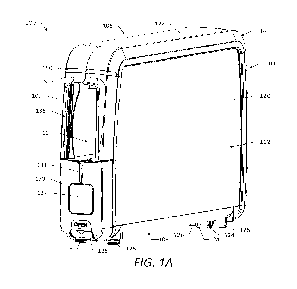
[0113] FIG. IA is a perspective view of a cutlery dispenser as may be
described herein.
[0114] FIG. IB is a partially-exploded perspective view of the cutlery
dispenser of FIG.
1A.
[0115] FIG. 1C is a perspective view of the cutlery dispenser of FIG. 1A.
[0116] FIG. 1D is a partially-exploded perspective view of the cutlery
dispenser of FIG.
1A.
[01171 FIG. lE is a perspective view of a portion of the cutlery dispenser of
FIG. 1A,
showing a front cover of the cutlery dispenser in an open position.
101181 FIG. 1F is a detailed perspective view of a portion of the cutlery
dispenser of FIG.
1A, showing a pusher assembly and sweeper arms of the cutlery dispenser.
[0119] FIG. IG is a perspective view of the front cover and a trough of the
cutlery
dispenser of FIG. 1A.
10120] FIG. 1H is a perspective view of the front cover and the trough of the
cutlery
dispenser of FIG. IA.
[0121] FIG. II is a perspective view of the front cover of the cutlery
dispenser of FIG.
1A.
101221 FIG. 1J is a perspective view of the front cover of the cutlery
dispenser of FIG.
1A.
[01231 FIG. 1K is a perspective view of the pusher assembly of the cutlery
dispenser of
FIG. 1A.
4
CA 03025872 2018-11-27
WO 2017/218521 PCT/US2017/037233
[0124] FIG. 1L is a perspective view of the pusher assembly of the cutlery
dispenser of
FIG. 1A.
[0125] FIG. 1M is a perspective view of a portion of the cutlery dispenser of
FIG. 1A,
showing a housing portion, a follower arm, a sweeper arm, and a biasing member
of the cutlery
dispenser.
[0126] FIG. 1N is a perspective view of the sweeper arms of the cutlery
dispenser of
FIG. IA.
[0127] FIG. 10 is a top view of the sweeper arms of the cutlery dispenser of
FIG. 1A.
[0128] FIG. IP is a perspective view of the follower arm of the cutlery
dispenser of FIG.
1A.
[0129] FIG. 1Q is a perspective view of the follower arm of the cutlery
dispenser of FIG.
1A.
[0130] FIG. IR is a cross-sectional side view of the cutlery dispenser of FIG.
1A,
showing the pusher assembly in a rearward position relative to a housing of
the cutlery dispenser.
[0131] FIG. 1S is a cross-sectional side view of the cutlery dispenser of FIG.
1A,
showing the pusher assembly in a forward position relative to the housing.
[0132] FIG. 2A is a front view of a cutlery utensil that may be used with the
cutlery
dispenser of FIG. 1A.
101331 FIG. 2B is a side view of the cutlery utensil of FIG. 2A.
[0134] FIG. 2C is a front view of the cutlery utensil of FIG. 2A, with a
wrapper
enclosing a functional head of the cutlery utensil.
[0135] FIG. 2D is a side view of the cutlery utensil of FIG. 2A, with the
wrapper
enclosing the functional head of the cutlery utensil.
[0136] FIG. 2E is a side view of a skewer that may be used with a number of
the cutlery
utensils of FIG. 2A and the cutlery dispenser of FIG. IA.
[0137] FIG. 2F is a top view of the skewer of FIG. 2E.
[0138] FIG. 2G is a side view of a number of the cutlery utensils of FIG. 2A
and the
skewer of FIG. 2E, showing the skewer extending through skewer apertures of
the cutlery
utensils to maintain the cutlery utensils in a stack.
[0139] FIG. 3A is a cross-sectional side view of a portion of the cutlery
dispenser of FIG.
1A, showing the front cover of the cutlery dispenser in an open position.
CA 03025872 2018-11-27
WO 2017/218521 PCT/US2017/037233
[0140] FIG. 3B is a cross-sectional side view of the cutlery dispenser of FIG.
1A,
showing the front cover in an open position and a number of the cutlery
utensils of FIG. 2A
positioned on the skewer of FIG. 2E and partially within the trough of the
cutlery dispenser.
[0141] FIG. 3C is a cross-sectional side view of the cutlery dispenser of FIG.
1A,
showing the front cover in a closed position and the number of the cutlery
utensils of FIG. 2A
positioned on the skewer of FIG. 2E and within an interior space of the
housing of the cutlery
dispenser.
[0142] FIG. 3D is a cross-sectional side view of the cutlery dispenser of FIG.
1A,
showing the front cover in the closed position and the number of the cutlery
utensils of FIG. 2A
positioned within the interior space.
[0143] FIG. 3E is a cross-sectional side view of a portion of the cutlery
dispenser of FIG.
IA, showing the front cover in an open position and a number of the cutlery
utensils of FIG. 2A
positioned within the interior space and retained therein by the sweeper arms
of the cutlery
dispenser.
[0144] FIG. 3F is a front view of a portion of the cutlery dispenser of FIG.
lA with the
front cover removed from view, showing the number of the cutlery utensils of
FIG. 2A
positioned within the interior space and retained therein by the sweeper arms.
[0145] FIG. 3G is a cross-sectional side view of a portion of the cutlery
dispenser of FIG.
1A, showing the front cover in an open position, the number of the cutlery
utensils of FIG. 2A
positioned within the interior space and retained therein by the sweeper arms,
and a number of
the cutlery utensils of FIG. 2A positioned on the skewer of FIG. 2E and
partially within the
trough of the cutlery dispenser.
DETAILED DESCRIPTION
[0146] The present disclosure includes example embodiments of cutlery
dispensers and
related methods for dispensing cutlery utensils to address one or more of the
concerns discussed
above. Reference is made herein to the accompanying drawings illustrating the
example
embodiments of the disclosure, in which use of the same reference numerals
indicates similar or
identical features or components. Throughout the disclosure, depending on the
context, singular
and plural terminology may be used interchangeably.
6
CA 03025872 2018-11-27
WO 2017/218521 PCT/US2017/037233
[0147] Referring now to the drawings, FIGS. IA-1S show an example embodiment
of a
cutlery dispenser 100 as may be described herein. The cutlery dispenser 100
may have a
generally rectangular shape configured to be oriented in an upright manner, as
shown in FIG. 1A,
although other suitable shapes and configurations of the cutlery dispenser 100
may be used in
other embodiments. During use, the cutlery dispenser 100 may be oriented in
the upright manner
and positioned on a countertop or other support surface in a particular
working environment,
such as a restaurant, although other suitable orientations and positions of
the cutlery dispenser
100 may be used. In certain embodiments, the cutlery dispenser 100 may be
configured to be
free-standing and portable, such that the cutlery dispenser 100 may be placed
on any countertop
or other support surface and may be easily moved from one position to another
position thereon.
In other embodiments, the cutlery dispenser 100 may be configured to be
temporarily or
permanently mounted and fixed to a countertop or other support surface. For
example, the
cutlery dispenser 100 may be mounted to a base or other support structure to
securely maintain a
desired orientation and position of the cutlery dispenser 100 with respect to
the countertop or
other support structure.
[0148] As described in detail below, the cutlery dispenser 100 may be
configured to
dispense a number of cutlery utensils 200 therefrom one at a time on demand.
FIGS. 2A and 2B
show an example cutlery utensil 200 that may be used with the cutlery
dispenser 100. Although
the cutlery utensil 200 is shown as a fork in FIGS. 2A and 2B, the utensil 200
may be any type of
cutlery utensil, including, for example, a fork, a spoon, a knife, or a spork.
In certain
embodiments, the cutlery utensil 200 may be disposable and may be constructed
of a moldable
material, although other suitable materials may be used. The moldable material
may include a
plastic, a combination of plastics, or other materials suitable for use in
forming cutlery utensils.
For example, the moldable material may include one or more of polystyrene,
polyethylene, and
polypropylene. For instance, in certain embodiments, the cutlery utensil 200
may be constructed
of recyclable and/or compostable materials.
[0149] As shown in FIGS. 2A and 2B, the cutlery utensil 200 may include a
functional
head 202, a handle 204, and a neck 206. The functional head 202 may extend
from a first end of
the cutlery utensil 200 and may be configured to perform a function to assist
a user in the
consumption of food. For example, the functional head 202 may be configured to
cut, pierce,
and/or scoop certain types of food for consumption. The handle 204 may extend
from an
7
CA 03025872 2018-11-27
WO 2017/218521 PCT/US2017/037233
opposite second end of the cutlery utensil 200 and may be configured to be
grasped by the user
for holding and/or manipulating the utensil 200. The neck 204 may be
positioned between and
connect the functional head 202 and the handle 204 and may provide a smooth
transition
therebetween. In certain embodiments, the cutlery utensil 200 may not include
the neck 206,
such that the handle 204 is connected to and extends directly from the
functional head 202. The
cutlery utensil 200 may be shaped and contoured as shown in FIGS. 2A and 2B,
although other
shapes and contours of the utensil 200 may be used.
[0150] As shown, the cutlery utensil 200 may include a skewer aperture 208
extending
therethrough from a front surface 210 to a back surface 212 of the utensil
200. The skewer
aperture 208 may be configured to receive a skewer 240 or other type of
joinder member or
loading member therethrough to facilitate loading of a number of the cutlery
utensils 200 into the
cutlery dispenser 100, as described below. In certain embodiments, as shown,
the skewer
aperture 208 may be defined in the handle 204 of the cutlery utensil 200 and
spaced apart from
the second end of the utensil 200, although other suitable locations of the
skewer aperture 220
may be used. The skewer aperture 208 may have an elongated shape having a
length extending
along the length of the cutlery utensil 200 and a width extending along the
width of the cutlery
utensil 200. In certain embodiments, as shown, the skewer aperture 208 may
have an elongated
racetrack shape having rounded ends, although other shapes of the skewer
aperture 208 may be
used.
101511 As shown in FIG. 2B, a thickness T of the handle 204 of the cutlery
utensil 200
may vary along the length of the handle 204. The handle 204 may include a
first portion 214
having a constant or substantially constant thickness T along the length of
the first portion 214,
and a second portion 216 having a varying thickness T along the length of the
second portion
216. In certain embodiments, as shown, the front and back surfaces of the
handle 204 may be
parallel or substantially parallel to one another along the length of the
first portion 214, and the
front and back surfaces of the handle 204 may be oriented at an acute angle a
relative to one
another along the length of the second portion 216. As described in detail
below, the angled
shape of the second portion 216 may assist in allowing a number of the cutlery
utensils 200 to be
fanned when positioned within the cutlery dispenser 100, which may allow a
user to easily grasp
and dispense a leading cutlery utensil 200. The acute angle a between the
front and back
surfaces of the handle 204 along the second portion may be between one (1)
degree and forty-
8
CA 03025872 2018-11-27
WO 2017/218521 PCT/US2017/037233
five (45) degrees, between one (1) degree and thirty (30) degrees, between one
(1) degree and
twenty (20) degrees, between one (1) degree and ten (10) degrees, or between
one (1) degree and
six (6) degrees, depending on the degree of fanning desired, although other
values of the acute
angle a may be used. It will be appreciated that various types and
configurations of cutlery
utensils other than the type and configuration of the cutlery utensil 200
shown in FIGS. 2A and
2B may be used with the cutlery dispenser 100.
[0152] In certain embodiments, as shown in FIGS. 2C and 2D, a wrapper 230 may
enclose at least a portion of the cutlery utensil 200. For example, according
to the illustrated
embodiment, the wrapper 230 may enclose the functional head 202 and at least a
portion of the
neck 206 of the cutlery utensil 200. In other embodiments, the wrapper 230 may
enclose only
the functional head 202 or at least an end portion thereof In still other
embodiments, the
wrapper 230 may enclose the entire cutlery utensil 200. By enclosing a portion
of the cutlery
utensil 200, the wrapper 230 may protect the enclosed portion of the utensil
200 from
contamination prior to and during dispensing of the utensil 200 from the
cutlery dispenser 100.
It will be appreciated that in those embodiments in which the wrapper 230
encloses the entire
cutlery utensil 200 or at least covers the portion about the skewer aperture
208, the wrapper 230
will include a corresponding aperture (not shown) therein so as to allow a
skewer or the like to
pass therethrough. The wrapper 230 may be constructed of a thin layer of
disposable packaging
material, which may be at least substantially sealed to contain the enclosed
portion of the cutlery
utensil 200 therein. In certain embodiments, the wrapper 230 may be
constructed of a plastic,
including, for example, polyethylene, and the sealed portions of the wrapper
230 may be formed
by heat sealing or glue sealing the plastic around the enclosed portion of the
cutlery utensil 200.
Other suitable materials of construction may be used to form the wrapper 230,
and other suitable
methods of forming the sealed regions may be used. It is also contemplated
that each of the
cutlery utensil embodiments contemplated by the present invention may be
wrapper free. In
other words, the cutlery dispenser 100 may be used to dispense a cutlery
utensil 200 that does not
have a wrapper 230 enclosing any portion of the utensil 200.
[0153] FIGS. 2E and 2F show an example skewer 240 that may be used with a
number
of the cutlery utensils 200 and the cutlery dispenser 100 to facilitate
loading of the utensils 200
into the dispenser 100 and/or unloading of the utensils 200 from the dispenser
100. As shown,
the skewer 240 may have an elongated shape and may include a retainer head
242, a handle 244,
9
CA 03025872 2018-11-27
WO 2017/218521 PCT/US2017/037233
and a shank 246. The retainer head 242 may extend from a first end of the
skewer 240 and may
be configured to be inserted through the skewer apertures 208 of the cutlery
utensils 200 and to
releasably retain the utensils 200 on the skewer 240. In certain embodiments,
as shown, the
retainer head 242 may include a pair of retainer arms 248 spaced apart from
one another and
configured to deflect towards one another when the retainer head 242 is
inserted through the
skewer aperture 208 of the cutlery utensil 200. Each retainer arm 248 may
include a barb 250
positioned at or near the free end of the retainer arm 248 and configured to
releasably retain the
cutlery utensil 200 on the skewer 240 when the retainer head 242 is inserted
within the skewer
aperture 208 of the utensil 200. The handle 244 may extend from an opposite
second end of the
skewer 240 and may be configured to be grasped by a user for holding and/or
manipulating the
skewer 240. As shown, the cross-sectional shape of the handle 244 may be
larger than the cross-
sectional shape of the skewer aperture 208 of the cutlery utensil 200, such
that the handle 244 is
prevented from being inserted into the skewer aperture 208. The shank 246 may
be positioned
between and connect the retainer head 242 and the handle 244 and may be
configured to be
inserted through the skewer apertures 208 of the cutlery utensils 200. The
skewer 240 may be
shaped and contoured as shown in FIGS. 2E and 2F, although other shapes and
contours of the
utensil 200 may be used. It will be appreciated that various configurations of
the skewer 240 or
other joinder members may be used with the cutlery utensils 200 and the
cutlery dispenser 100.
For example, the skewer 240 may have a more complex configuration than the
illustrated
embodiment and/or may include multiple components configured to interact with
the cutlery
utensils 200 and the cutlery dispenser 100.
101541 FIG. 2G shows the skewer 240 with a number of the cutlery utensils 200
positioned thereon in a stack, such that the utensils 200 are arranged in a
nested manner.
Although twenty (20) cutlery utensils 200 are shown positioned on the skewer
240 in the
illustrated embodiment, the skewer 240 may be configured to retain any
suitable number of
cutlery utensils 200. As shown, the skewer 240 may be inserted through the
skewer apertures
208 of the cutlery utensils 200, such that the shank 246 and at least a
portion of the retainer head
242 are positioned therethrough and the retainer arms 248 retain the cutlery
utensils 200 on the
skewer 240. The corresponding cross-sectional shapes of the shank 246 and the
skewer
apertures 208 may prevent or restrict the cutlery utensils 200 from rotating
relative to the skewer
240, such that all of the cutlery utensils 200 are retained in a common
orientation. The cutlery
CA 03025872 2018-11-27
WO 2017/218521 PCT/US2017/037233
utensils 200 may be loaded onto the skewer 240 by inserting the retainer head
242 through the
skewer apertures 208 of the utensils 200 and advancing the utensils along the
shank 246 toward
the handle 244. As the barbs 250 pass through each skewer aperture 208, the
retainer arms 248
may deflect towards one another and then assume their relaxed state after the
barbs 250 pass
through the skewer aperture 208. In this manner, the cutlery utensils 200 may
be retained on the
shank 246 and/or the retainer head 242 of the skewer 240. The cutlery utensils
200 may be
removed from the skewer 240 by restraining the relative position of the
utensils 200, for example
by one or more components of the cutlery dispenser 100 contacting one or more
of the utensils
200, and pulling the handle 244 of the skewer 240 away from the utensils 200.
In particular, the
handle 244 may be pulled with sufficient force to cause the retainer arms 248
to deflect towards
one another such that the barbs 250 may pass through the skewer apertures 208
of the utensils
200. In this manner, the cutlery utensils 200 may be removed from the shank
246 and the
retainer head 242 of the skewer 240. As described in detail below, the skewer
240 may be used
to load the stack of the cutlery utensils 200 into the cutlery dispenser 100
in an easy and efficient
manner. The skewer 240 also may be used to unload a number of the cutlery
utensils 200 from
the cutlery dispenser 100 in an opposite manner, as described below.
[0155] Referring back to FIGS. 1A-1D, the cutlery dispenser 100 may have a
front 102, a
back 104, a top 106, a bottom 108, a first side 110, and a second side 112. It
will be appreciated
that the nomenclature associated with these sides of the cutlery dispenser 100
are with respect to
the upright orientation shown in FIGS. 1A-1D, and that the dispenser 100 may
be used in other
orientations. As shown, the cutlery dispenser 100 may include a housing 114
that includes a
number of walls and defines an interior space 116 therein, inward from the
walls of the housing
114. The interior space 116 may be configured to receive a number of the
cutlery utensils 200
therein and to contain various components of the cutlery dispenser 100
therein. In certain
embodiments, as shown, the housing 114 may include a number of portions that
are separately
formed and attached to one another. For example, the housing 114 may include a
first housing
portion 118, a second housing portion 120, and a top cover 122 that are
separately formed and
attached to one another. In certain embodiments, the first housing portion 118
and the second
housing portion 120 may be mirror images or substantially mirror images of one
another. As
shown, the first housing portion 118 may define at least a portion of each of
the front 102, the
back 104, the top 106, the bottom 108, and the first side 110 of the cutlery
dispenser 100, and the
11
CA 03025872 2018-11-27
WO 2017/218521 PCT/US2017/037233
second housing portion 120 may define at least a portion of each of the front
102, the back 104,
the top 106, the bottom 108, and the second side 112 of the cutlery dispenser
100. The first
housing portion 118 and the second housing portion 120 each may include one or
more feet 124
or other leveling features positioned along the bottom thereof and configured
to support the
cutlery dispenser 100 on a countertop or other support surface in the upright
orientation.
Additionally or alternatively, the first housing portion 1 l 8 and the second
housing portion 120
each may include one or more mounting tabs 126 positioned along the bottom
surface thereof
and configured to securely engage mating receptacles of a base or platform on
which the cutlery
dispenser 100 may be mounted. For example, the mounting tabs 126 may be
configured to form
a snap fit with the mating receptacles to securely mount the cutlery dispenser
100 to the base or
platform. In certain embodiments, as shown, the first housing portion 118 and
the second
housing portion 120 may be securely attached to one another by one or more
fasteners 128, such
as screws, although other attachment mechanisms may be used. The top cover 122
may be
positioned over and attached to each of the first housing portion 118 and the
second housing
portion 120. As shown, the top cover 122 may define at least a portion of each
of the front 102,
the back 104, the top 106, the first side 110, and the second side 112 of the
cutlery dispenser 100.
The housing 114 may be constructed of any suitable type of substantially rigid
material including
thermoplastics, such as polypropylene, metals, such as aluminum, composite
materials, or other
suitable materials. It will be appreciated that various shapes and
configurations of the housing
114 may be used with the cutlery dispenser 100.
[0156] The cutlery dispenser 100 also may include a front cover 130 and a
trough 132
attached to the front cover 130. In some embodiments, as shown, the front
cover 130 and the
trough 132 may be separately formed and attached to one another. For example,
the front cover
130 and the trough 132 may be attached to one another by one or more fasteners
134, such as
screws, although other attachment mechanisms may be used. In other
embodiments, the front
cover 130 and the trough 132 may be integrally formed with one another as a
single component.
The front cover 130 and the trough 132 may be configured to move relative to
the housing 114
between a closed position, as shown in FIG. 1A, for dispensing of the cutlery
utensils 200 from
the cutlery dispenser 100, and an open position, as shown in FIG. 1E, for
loading the cutlery
utensils 200 into the interior space 116 of the dispenser 100. In particular,
the front cover 130
and the trough 132 may be configured to slide or translate relative to the
housing 114 between
12
CA 03025872 2018-11-27
WO 2017/218521 PCT/US2017/037233
the closed position and an open position. It will be appreciated that the
front cover 130 and the
trough 132 may have a number of open positions, depending on the extent to
which the front
cover 130 and the trough 132 are moved relative to the housing 114. When the
front cover 130
and the trough 132 are in the closed position, the front cover 130 may
partially enclose the
interior space 116, such that a dispensing opening 136 of the cutlery
dispenser 100 is defined
between respective portions of the front cover 130 and the housing 114. As
described below, a
leading cutlery utensil 200 (i.e., the cutlery utensil 200 positioned closest
to the dispensing
opening 136 and within the interior space 116 of the housing 114) may extend
through the
dispensing opening 136, such that a user may grasp and remove the leading
cutlery utensil 200
through the dispensing opening 136. As shown, the front cover 130 may be
positioned along a
bottom portion of the front 102 of the cutlery dispenser 100, and the
dispensing opening 136 may
be positioned along a top portion of the front 102 of the dispenser 100,
although other positions
of the front cover 130 and the dispensing opening 136 may be used.
10157] In certain embodiments, as shown, the front cover 130 may include an
indicator
portion 137 positioned along the front of the cover 130 and visible to a user.
The indicator
portion 137 may include an indicator, such as a symbol, a word, or a braille
pattern, which
indicates the type of cutlery utensil 200 contained within the cutlery
dispenser 100 and/or
provides a decorative feature for branding or marketing purposes. In certain
embodiments, as
shown, the indicator portion 137 may be removably attached to a remainder of
the front cover
130, for example by a snap-fit connection. In this manner, the indicator
portion 137 may be
removed and replaced with a different indicator portion 137 when the type of
cutlery utensil 200
to be dispensed from the dispenser 100 is changed. As shown, the front cover
130 may include a
locking tab 138, which may be positioned along the bottom of the front cover
130 and may be
configured to releasably engage a locking receptacle 140 defined in the
housing 114 when the
front cover 130 is in the closed position. In this manner, the locking tab 138
and the locking
receptacle 140 may form a releasable lock to prevent the front cover 130 from
inadvertently
moving from the closed position to an open position. The locking tab 138 may
be disengaged
from the locking receptacle 140 by deflecting the locking tab 138 away from
the locking
receptacle 140, thereby allowing the front cover 130 to be moved to an open
position. The front
cover 130 also may include a skewer slot 141 defined therein and configured to
allow a portion
of the skewer 240 to be received within the slot 141. As described below, the
skewer slot 141
13
CA 03025872 2018-11-27
WO 2017/218521 PCT/US2017/037233
may facilitate alignment of the skewer 420 relative to the front cover 130 and
the overall cutlery
dispenser 100 during loading of the cutlery utensils 200 into the dispenser
100 via the skewer
240. In certain embodiments, as shown, the skewer slot 141 may extend
vertically from the top
of the front cover 130, although other orientations and positions of the
skewer slot 141 may be
used.
[0158] The front cover 130 also may include a wedge protrusion 142 positioned
along
the vertical interior surface of the front cover 130 and extending inward
therefrom. As described
in detail below, the wedge protrusion 142 may be configured to engage a
portion of the leading
cutlery utensil 200, such as a portion of the handle 204 of the leading
cutlery utensil 200, such
that the leading cutlery utensil 200 is tilted forward (i.e., toward the front
102 of the dispenser
100) from an upright position to a tilted position and a portion of the
leading cutlery utensil 200,
such as the functional head 202 of the leading cutlery utensil 200, extends at
least partially
through the dispensing opening 136 and outside of the interior space 116. In
this manner, the
wedge protrusion 142 may cause the leading cutlery utensil 200 and a number of
subsequent
cutlery utensils 200 (i.e., cutlery utensils 200 positioned further from the
dispensing opening 136
than the leading cutlery utensil 200) to assume a fanned arrangement, with the
functional heads
202 of these utensils 200 spaced apart from one another to facilitate
dispensing. As shown, the
wedge protrusion 142 may include one or more contact surfaces 144 configured
to engage the
front surface of the handle 204 of the leading cutlery utensil 200 such that
the leading cutlery
utensil 200 is tilted from the upright position to the tilted position.
According to the illustrated
embodiment, the wedge protrusion 142 may include three (3) contact surfaces
144, although any
suitable number of contact surfaces 144 may be used. In particular, the wedge
protrusion 142
may include a bottom contact surface 144a, an intermediate contact surface
144b, and a top
contact surface 144c. As shown, each of the contact surfaces 144 may be
oriented at an acute
angle relative to the vertical interior surface of the front cover 130. In
certain embodiments, the
acute angle of the bottom contact surface 144a may be less than the acute
angle of the
intermediate contact surface 144b, and the acute angle of the intermediate
contact surface 144b
may be less than the acute angle of the top contact surface 144c, although
other configurations of
the contact surfaces 144 may be used. According to the illustrated embodiment,
each of the
contact surfaces 144 may be a planar surface. In other embodiments, one or
more of the contact
surfaces 144 may be a curved surface or otherwise may be contoured to have a
non-planar shape.
14
CA 03025872 2018-11-27
WO 2017/218521 PCT/US2017/037233
Although the wedge protrusion 142 is shown as being part of the front cover
130, the wedge
protrusion 142 alternatively may be part of the trough 132.
[0159] As shown, the trough 132 may extend inward from the front cover 130 and
may
move therewith when the front cover 130 is moved between the closed position
and an open
position. The trough 132 may have an elongated shape and may include a base
146 having a U-
shaped cross-sectional shape, and a pair of flanges 148 extending laterally
from the base 146.
The base 146 may be configured to receive a portion of each of the cutlery
utensils 200 in the
cutlery dispenser 100. In particular, according to the illustrated embodiment,
the base 146 may
be configured to receive a portion of the handle 204 of each of the cutlery
utensils 200 therein.
In other embodiments, the base 146 may be configured to receive a portion of
the functional
head 202 of each of the cutlery utensils 200 therein. As shown, each of the
flanges 148 may be
movably received between a pair of guide rails 150 of the housing 114. In this
manner, the guide
rails 150 may guide the sliding horizontal movement of the trough 132 relative
to the housing
114 and may prevent or restrict vertical movement of the trough 132 relative
to the housing 114.
As shown in FIGS. 1G and 1H, the trough 132 may include a stop tab 152
configured to engage
a stop protrusion 154 of the housing 114 to limit the sliding movement of the
trough 132 relative
to the housing 114. In certain embodiments, the stop tab 152 may be positioned
on one of the
flanges 148 of the trough 132, although other positions of the stop tab 152
may be used. The
stop tab 152 effectively may define a fully open position of the front cover
130 and the trough
132 relative to the housing 114. In this manner, the stop tab 152 may prevent
or restrict the
trough 132 from being completely removed from the interior space 116 of the
housing 114. As
shown, the trough 132 also may include a stop wall 155 positioned at or near
the end of the
trough 132 opposite the front cover 130 and extending vertically along the
height of the base
146. The stop wall 155 effectively may limit the number of the cutlery
utensils 200 that may be
positioned within the trough 132. In particular, the stop wall 155 may be
configured to engage a
trailing cutlery utensil 200 (i.e., the cutlery utensil 200 positioned
furthest from the dispensing
opening 136) when the cutlery dispenser 100 is at a maximum fill level. In
this manner, the stop
wall 155 may prevent overloading of cutlery utensils 200 in the cutlery
dispenser 100, which
might otherwise result in jamming of the dispenser 100 and/or subjecting one
or more
components of the dispenser 100 to undesirable stresses.
CA 03025872 2018-11-27
WO 2017/218521 PCT/US2017/037233
[0160] The cutlery dispenser 100 also may include a pushing assembly 156
movably
positioned within the interior space 116 of the dispenser 100 and configured
to push or advance
the cutlery utensils 200 toward the front 102 of the dispenser 100. As shown
in FIGS. 1K-1L,
the pusher assembly 156 may include a support member 158 and one or more
biasing members
160. The support member 158 may be configured to translate or slide relative
to the housing 114
in a direction extending from the front 102 of the dispenser 100 to the back
104 of the dispenser
100, and the biasing member 160 may be configured to bias the support member
158 toward the
front 102 of the dispenser 100 and into engagement with the trailing cutlery
utensil 200 loaded in
the dispenser 100. As shown, the support member 158 may include a contact
surface 162
positioned along the front of the support member 158 and configured to engage
the back surface
of the trailing cutlery utensil 200. The support member 158 also may include a
number of arms
164 extending laterally and configured to movably engage respective guide
rails 166 of the
housing 114. In this manner, the guide rails 166 may guide the sliding
horizontal movement of
the support member 158 relative to the housing 114 and may prevent or restrict
vertical
movement of the support member 158 relative to the housing 114. The support
member 158 also
may include a guide post 168 extending vertically upward and configured to
movably engage a
follower arm 170 of the cutlery dispenser 100. As shown, the support member
158 may include
a skewer opening 171 defined in the front of the support member 158 and
configured to receive a
portion of the skewer 240 therein during loading of the cutlery utensils 200
into the dispenser
100. In particular, the skewer opening 171 may facilitate alignment of the
skewer 240 and the
cutlery utensils 200 positioned thereon with respect to the dispenser 100
during loading the
utensils 200, as described below. The biasing member 160 may be securely
attached to the
housing 114, for example by a fastener 172, such as a screw, and may be
configured to engage a
back surface of the support member 158. In this manner, the biasing member 160
may bias the
support member 158 toward the front 102 of the dispenser 100 and into
engagement with the
trailing cutlery utensil 200. In certain embodiments, as shown, the biasing
member 160 may be a
constant force spring, although other types of springs or biasing members may
be used.
[0161] As shown, the follower arm 170 may positioned within a top portion of
the
interior space 116 of the housing 114 and may be pivotally attached to the
housing 114. In this
manner, the follower arm 170 may pivot relative to the housing 114 during use
of the dispenser
100. As shown in FIGS. 1P and 1Q, the follower arm 170 may include a contact
surface 174
16
CA 03025872 2018-11-27
WO 2017/218521 PCT/US2017/037233
positioned along the bottom of the follower arm 170 and configured to engage
the guide post 168
of the support member 158. The contact surface 174 may be contoured as shown,
such that the
follower arm 170 pivots relative to the housing 114 when the support member
158 translates
relative to the housing 114. In particular, as shown in FIGS. 1R and is, the
follower arm 170
may pivot upward relative to the housing 114 when the support member 158
translates toward
the front 102 of the cutlery dispenser 100. As shown, the follower arm 170 may
include a pair of
guide ribs 176 extending along the contact surface 174 and spaced apart from
one another to
guide the support member 158 as the follower arm 170 and the support member
158 move
relative to the housing 114. As shown in FIG. 1M, the follower arm 170 may
include a number
of indicators 178 configured to indicate a fill level of the cutlery utensils
200 loaded within the
interior space 116 of the cutlery dispenser 100 and/or to indicate whether
additional cutlery
utensils 200 may be loaded into the interior space 116 of the dispenser 100.
In certain
embodiments, as shown, the follower arm 170 may include three (3) indicators
178, although any
number of the indicators 178 may be used. A first indicator 178a may indicate
that the dispenser
100 is full or nearly full, a second indicator 178b may indicate that the
dispenser 100 is partially
full, and a third indicator 178c may indicate that the dispenser 100 is empty
or nearly empty. In
certain embodiments, the indicators 178 may be colored-coded, with each
indicator 178 being a
different color. For example, the first indicator 178a may be green, the
second indicator 178b
may be yellow, and the third indicator 178c may be red, although other colors
may be used for
the indicators 178. In certain embodiments, the indicators 178 may indicate
whether an
additional stack of the cutlery utensils 200 (i.e., the number of the cutlery
utensils 200 that may
be loaded on the skewer 240 at once) may be loaded into the dispenser 100. For
example, the
first indicator 178a may indicate that no additional full stacks of the
utensils 200 may be loaded
into the dispenser 100, the second indicator 178b may indicate that one
additional stack of the
utensils 200 may be loaded into the dispenser 100, and the third indicator
178c may indicate that
two additional stacks of the utensils 200 may be loaded into the dispenser
100. It will be
understood that the indicators 178 may provide any type of visual indication,
such as colors,
symbols, numbers, or words. During use of the cutlery dispenser 100, one of
the indicators 178
may be visible through an indicator window 180 of the housing 114, while the
remaining
indicators 178 are hidden from view. Other configurations may allow for a
transition between
two of the indicators 178. In certain embodiments, as shown, the indicator
window 180 may be
17
CA 03025872 2018-11-27
WO 2017/218521 PCT/US2017/037233
positioned along the front 102 of' the dispenser 100, although other positions
of the indicator
window 180, such as along the top 106 or one of the sides 110, 112 of the
dispenser 100, may be
used. As the follower arm 170 pivots relative to the housing 114, the
indicator 178 that is visible
through the indicator window 180 may allow a user to determine the fill level
of the cutlery
utensils 200 loaded within the interior space 116 of the cutlery dispenser 100
and/or whether
additional utensils 200 may be loaded into the interior space 116 of the
dispenser 100. Although
the indicators 178 are shown as being part of the follower arm 170 in the
illustrated embodiment,
the indicators 178 alternatively may be part of the support member 158, and
the indicator
window 180 may be configured to allow the different indicators 178 to be
viewed as the support
member 158 translates relative to the housing 114.
[0162] The cutlery dispenser 100 also may include a pair of sweeper arms 182
securely
attached to the housing 114 and configured to retain the cutlery utensils 200
within the interior
space 116 of the housing 114 as the cutlery utensils 200 are loaded into the
dispenser 100. In
certain embodiments, the sweeper arms 182 may be attached to the housing 114
by one or more
of the fasteners 172, although other attachment mechanisms may be used. The
sweeper arms
182 may be spaced apart from and positioned opposite one another, such that
the cutlery utensils
200 may be inserted therebetween. As shown in FIGS. IN and 10, each sweeper
arm 182 may
include a barb 184 positioned along a front end of the sweeper arm 182 and
configured to engage
the cutlery utensils 200. In particular, the barb 184 may include a lead-in
surface 186 configured
to engage the back surface of a cutlery utensil 200 as the utensil 200 is
inserted between the
sweeper arms 182, and a contact surface 188 configured to engage the front
surface of the cutlery
utensil 200 after the utensil 200 is inserted past the barb 184. The sweeper
arms 182 may be
spaced apart and configured to deflect away from one another when the cutlery
utensil 200
engages the lead-in surfaces 186 and then return to their original, relaxed
position after the
utensil 200 is inserted past the barb 184. The cutlery utensil 200
subsequently may be biased
into engagement with the contact surfaces 188 by the pushing assembly 156. As
described
below, the sweeper arms 182 may engage the leading cutlery utensil 200 and
maintain the loaded
cutlery utensils 200 within the interior space 116 of the dispenser 100 when
the front cover 130
is in an open position and may disengage (i.e., be spaced apart from and not
in contact with) the
leading cutlery utensil 200 when the front cover 130 is in the closed
position.
18
CA 03025872 2018-11-27
WO 2017/218521 PCT/US2017/037233
[0163] FIGS. 3A-3D illustrate an example method of loading a number of the
cutlery
utensils 200 into the cutlery dispenser 100 and dispensing the loaded cutlery
utensils 200 (i.e.,
the utensils 200 positioned within the interior space 116 of the housing 114)
from the cutlery
dispenser 100. The front cover 130 may be moved relative to the housing 114
from the closed
position to an open position, as shown in FIG. 3A. In particular, the locking
tab 138 of the front
cover 130 may be depressed to disengage the locking receptacle 140 of the
housing 114, and the
front cover 130 may be pulled away from the front of the housing 114 along
with the trough 132.
As described above, the front cover 130 may be pulled until the stop tab 152
of the trough 132
engages the stop protrusion 154 of the housing 114, such that the front cover
130 and the trough
132 are in the fully open position, as shown. A number of the cutlery utensils
200, previously
loaded on the skewer 240, then may be inserted between the front cover 130 and
the pushing
assembly 156 via the skewer 240 while the skewer 240 is received within and
extends through
the skewer slot 141 and the handle 244 of the skewer 240 remains at least
partially in front of the
front cover 130, as shown in FIG. 3B. In particular, the handles 204 of the
cutlery utensils 200
may be inserted into the base 146 of the trough 132, as shown. In this manner,
the cutlery
utensils 200 may be oriented in an upright or substantially upright manner
with the functional
heads 202 of the utensils 200 positioned above the handles 204 of the utensils
200. This
orientation of the cutlery utensils 200 advantageously may allow the cutlery
dispenser 100 to
receive and dispense any suitable type of utensil 200 (e.g., forks, spoons,
knives, sporks, etc.)
having a handle 204 configured to be received within the trough 132 and a body
that is sized to
functionally fit within the dispenser 100.
[0164] After inserting the handles 204 of the cutlery utensils 200 into the
trough 132, the
front cover 130 and the trough 132 may be moved relative to the housing 114
from the open
position to the closed position, as shown in FIG. 3C. As the front cover 130
is closed, the cutlery
utensils 200 may pass between the sweeper arms 182 and into the interior space
116 of the
dispenser 100, each utensil 200 engaging the lead-in surfaces 186 of the barbs
184 and deflecting
the sweeper arms 182 away from one another as the utensil 200 is inserted
therebetween.
Additionally, as the front cover 130 is closed, the trailing cutlery utensil
200 should engage the
contact surface 162 of the support member 158, thereby moving the support
member 158 toward
the back 104 of the dispenser 100 and unfurling the biasing member 160 toward
the back 104 of
the dispenser 100. The biasing member 160 may bias the support member 158
toward the front
19
CA 03025872 2018-11-27
WO 2017/218521 PCT/US2017/037233
102 of the dispenser 100 such that the contact surface 162 maintains
engagement with the back
surface of the trailing cutlery utensil 200. As the support member 158 moves
toward the back
104 of the dispenser 100, the guide post 168 of the support member 158 may
move along the
contoured contact surface 174 of the follower arm 170 such that the follower
arm 170 pivots
upward relative to the housing 114 and the visible indicator 178 indicates the
fill level of the
cutlery utensils 200 loaded in the dispenser 100 or available capacity of the
dispenser 100.
When the front cover 130 and the trough 132 reach the closed position, the
locking tab 138 of the
front cover 130 may engage the locking receptacle 140 of the housing 114,
thereby preventing
the front cover 130 from being inadvertently moved toward an open position.
101651 After moving the front cover 130 and the trough 132 to the closed
position, the
skewer 240 may be removed from the skewer apertures 208 of the cutlery
utensils 200, via the
skewer slot 141 of the front cover 130, and from the overall cutlery dispenser
100. In particular,
the skewer 240 may be removed from the skewer apertures 208 and the skewer
slot 141 by
pulling the skewer 240 away from the front cover 130, via the handle 244,
while the cutlery
utensils 200 are restrained by the sweeper arms 182 and/or the front cover
130. When the cover
130 is in the closed position and the skewer 240 is removed from the skewer
apertures 208 and
the skewer slot 141, the pushing assembly 156 may move the cutlery utensils
200 toward the
front 102 of the dispenser 100 and into engagement with the wedge protrusion
142, as shown in
FIG. 3D. In particular, the biasing member 160 is shown biasing the support
member 158
against the trailing cutlery utensil 200 such that the cutlery utensils 200
are compressed together
and the leading cutlery utensil 200 engages the wedge protrusion 142. As
shown, the front
surface of the handle 204 of the leading cutlery utensil 200 engages the wedge
protrusion 142
such that the leading cutlery utensil 200 is tilted toward the front 102 of
the dispenser 100 and at
least a portion of the functional head 202 of the leading cutlery utensil 200
extends through the
dispensing opening 136 and out of the dispenser 100. As shown, when the handle
204 of the
leading cutlery utensil 200 engages the wedge protrusion 142, the handle 204
desirably is
disengaged and spaced apart from the sweeper arms 182. In this manner, the
handle 204 of the
leading cutlery utensil 200 no longer engages the contact surfaces 188 of the
sweeper arms 182
when the front cover 130 is closed. The angled shape of the wedge protrusion
142 and the
angled shape of the second portions 216 of the cutlery utensils 200 may cause
the leading cutlery
utensil 200 and a number of the subsequent cutlery utensils 200 to assume a
fanned arrangement,
CA 03025872 2018-11-27
WO 20171218521 PCT/US2017/037233
as shown in FIG. 3D, with portions of the handles 204 of such utensils 200
abutting one another
and the functional heads 202 of such utensils 200 spaced apart from one
another.
[0166] The fanned arrangement of the cutlery utensils 200 may allow a user to
easily
grasp and pull the functional head 202 of the leading cutlery utensil 200,
such that the leading
cutlery utensil 200 may be removed from the cutlery dispenser 100. When the
leading cutlery
utensil 200 is removed from the dispenser 100, the biasing member 160 may move
the support
member 158 toward the front 102 of the dispenser 100 such that the contact
surface 162 of the
support member 158 maintains engagement with the back surface of the trailing
cutlery utensil
200 and all of the cutlery utensils 200 move into position for a subsequent
dispense.
[0167] FIGS. 3E-3G illustrate the function of the sweeper arms 182 when the
front cover
130 is moved to an open position while a number of the cutlery utensils 200
remain loaded in the
cutlery dispenser 100. As shown, in FIGS. 3E and 3F, when the front cover 130
is opened and
the leading loaded cutlery utensil 200 no longer engages the wedge protrusion
142, the cutlery
utensils 200 may move toward the front 102 of the dispenser 100 such that the
leading loaded
cutlery utensil 200 engages the contact surfaces 188 of the sweeper arms 182
and the cutlery
utensils 200 assume an upright position. With the front cover 130 in an open
position and the
loaded cutlery utensils 200 retained by the sweeper arms 182, additional
cutlery utensils 200 may
be loaded into the cutlery dispenser 182 via the skewer 240, as shown in FIG.
3G. Loading of
the additional cutlery utensils 200 may be carried out in the manner described
above with respect
to FIGS. 3A-3D. Furthermore, the skewer 240 also may be used to facilitate
removal of the
loaded cutlery utensils 200 from the cutlery dispenser 100. For example, the
skewer 240 may be
inserted through the skewer slot 141 of the front cover 130 and through the
skewer apertures 208
of the loaded cutlery utensils 200, such that the utensils 200 are retained by
the skewer 240. The
front cover 130 then may be moved to an open position, and the cutlery
utensils 200 may be
pulled out of the interior space 116 of the housing 114 via the skewer 240. If
more utensils
remain than can be removed on one skewer, the process may be repeated until
all utensils are
removed.
[0168] In further embodiments, the present invention is:
[0169] A cutlery dispenser for dispensing cutlery utensils, the dispenser
comprising a
housing comprising an interior space configured to receive a plurality of
cutlery utensils loaded
therein; a cover enclosing a portion of the interior space and configured to
move between a
21
CA 03025872 2018-11-27
WO 2017/218521 PCT/US2017/037233
closed position for dispensing the loaded cutlery utensils from the interior
space and an open
position for loading the cutlery utensils into the interior space; a wedge
protrusion configured to
engage a leading one of the loaded cutlery utensils when the cover is in the
closed position and to
disengage the leading one of the loaded cutlery utensils when the cover is in
an open position;
and a pair of sweeper arms configured to engage the leading one of the loaded
cutlery utensils
when the cover is in an open position and to disengage the leading one of the
loaded cutlery
utensils when the cover is in the closed position.
[0170] A cutlery dispenser for dispensing cutlery utensils, the dispenser
comprising a
housing comprising an interior space configured to receive a plurality of
cutlery utensils loaded
therein; a cover enclosing a portion of the interior space and configured to
move between a
closed position for dispensing the loaded cutlery utensils from the interior
space and an open
position for loading the cutlery utensils into the interior space; and a
trough attached to the cover
and configured to receive handles of the loaded cutlery utensils therein,
wherein the trough
comprises a stop wall positioned at or near an end of the trough opposite the
cover and
configured to engage a trailing one of the loaded cutlery utensils when the
dispenser is at a
maximum fill level.
[0171] A cutlery dispenser for dispensing cutlery utensils, the dispenser
comprising a
housing comprising an interior space configured to receive a plurality of
cutlery utensils loaded
therein; a cover enclosing a portion of the interior space and configured to
translate relative to
the housing between a closed position for dispensing the loaded cutlery
utensils from the interior
space and an open position for loading the cutlery utensils into the interior
space; and a trough
attached to the cover and configured to receive handles of the loaded cutlery
utensils therein,
such that the loaded cutlery utensils are oriented in a substantially upright
manner with
functional heads of the loaded cutlery utensils positioned above the handles.
[0172] A cutlery dispenser for dispensing cutlery utensils, the dispenser
comprising a
housing comprising an interior space configured to receive a plurality of
cutlery utensils loaded
therein; a cover enclosing a portion of the interior space and configured to
move between a
closed position for dispensing the loaded cutlery utensils from the interior
space and an open
position for loading the cutlery utensils into the interior space; and a wedge
protrusion
configured to engage a leading one of the loaded cutlery utensils when the
cover is in the closed
position and to disengage the leading one of the loaded cutlery utensils when
the cover is in an
22
CA 03025872 2018-11-27
WO 2017/218521 PCT/US2017/037233
open position, wherein the wedge protrusion comprises a contact surface
oriented at an acute
angle relative to an interior surface of the cover.
[0173] A cutlery dispenser for dispensing cutlery utensils, the dispenser
comprising a
housing comprising an interior space configured to receive a plurality of
cutlery utensils loaded
therein; a cover enclosing a portion of the interior space and configured to
move between a
closed position for dispensing the loaded cutlery utensils from the interior
space and an open
position for loading the cutlery utensils into the interior space; and a
follower arm attached to the
housing and configured to pivot relative to the housing, wherein the follower
arm comprises one
or more indicators configured to indicate a fill level of the loaded cutlery
utensils within the
interior space.
[0174] A cutlery dispenser for dispensing cutlery utensils, the dispenser
comprising a
housing comprising an interior space configured to receive a plurality of
cutlery utensils loaded
therein; a cover enclosing a portion of the interior space and configured to
move between a
closed position for dispensing the loaded cutlery utensils from the interior
space and an open
position for loading the cutlery utensils into the interior space, wherein the
cover comprises a slot
configured to receive a skewer to facilitate loading of the cutlery utensils
into the interior space.
[0175] A cutlery dispenser according to any of the previous embodiments,
wherein the
wedge protrusion is positioned along an interior surface of the cover.
101761 A cutlery dispenser according to any of the previous embodiments,
wherein the
wedge protrusion comprises a contact surface oriented at an acute angle
relative to the interior
surface of the cover, and wherein the contact surface is configured to engage
the leading one of
the loaded cutlery utensils when the cover is in the closed position.
[0177] A cutlery dispenser according to any of the previous embodiments,
further
comprising a trough attached to the cover and configured to receive handles of
the loaded cutlery
utensils therein.
[0178] A cutlery dispenser according to any of the previous embodiments,
wherein the
trough comprises a stop tab, wherein the housing comprises a stop protrusion,
and wherein the
stop tab is configured to engage the stop protrusion when the cover is in a
fully open position to
limit movement of the cover relative to the housing.
23
CA 03025872 2018-11-27
WO 2017/218521 PCT/US2017/037233
[01791 A cutlery dispenser according to any of the previous embodiments,
further
comprising a pushing assembly positioned within the interior space and
configured to move the
loaded cutlery utensils toward the cover.
[0180] A cutlery dispenser according to any of the previous embodiments,
wherein the
pushing assembly comprises a support member configured to move relative to the
housing, and a
biasing member configured to bias the support member toward the cover.
[0181] A cutlery dispenser according to any of the previous embodiments,
wherein the
support member comprises a contact surface configured to engage a trailing one
of the loaded
cutlery utensils.
[0182] A cutlery dispenser according to any of the previous embodiments,
wherein the
biasing member comprises a constant force spring attached to the housing and
configured to
engage the support member.
[01831 A cutlery dispenser according to any of the previous embodiments,
wherein each
sweeper arm comprises a contact surface configured to engage the leading one
of the loaded
cutlery utensils when the cover is in an open position.
[01841 A cutlery dispenser according to any of the previous embodiments,
wherein each
sweeper arm comprises a lead-in surface configured to engage the cutlery
utensils as the cutlery
utensils are inserted into the interior space.
[0185] A cutlery dispenser according to any of the previous embodiments,
wherein the
sweeper arms are spaced apart from one another and configured to deflect away
from one
another as the cutlery utensils are inserted into the interior space.
[0186] A cutlery dispenser according to any of the previous embodiments,
further
comprising a follower arm attached to the housing and configured to pivot
relative to the housing
when the cover moves between the closed position and an open position.
[0187] A cutlery dispenser according to any of the previous embodiments,
further
comprising a dispensing opening defined by the housing and the cover and
configured to allow
the loaded cutlery utensils to be dispensed therethrough
[0188] A cutlery dispenser according to any of the previous embodiments,
wherein the
wedge protrusion is configured to tilt the leading one of the loaded cutlery
utensils when the
cover is in the closed position, such that a portion of the leading one of the
loaded cutlery
utensils extends through the dispensing opening.
24
CA 03025872 2018-11-27
WO 2017/218521 PCT/US2017/037233
[0189] A cutlery dispenser according to any of the previous embodiments,
wherein the
stop wall extends vertically along a height of the trough.
[01901 A cutlery dispenser according to any of the previous embodiments,
further
comprising a wedge protrusion configured to engage a leading one of the loaded
cutlery utensils
when the cover is in the closed position and to disengage the leading one of
the loaded cutlery
utensils when the cover is in an open position; and a pair of sweeper arms
configured to engage
the leading one of the loaded cutlery utensils when the cover is in an open
position and to
disengage the leading one of the loaded cutlery utensils when the cover is in
the closed position.
[0191] A cutlery dispenser according to any of the previous embodiments,
further
comprising a dispensing opening defined by the housing and the cover and
configured to allow
the loaded cutlery utensils to be dispensed therethrough.
[0192] A cutlery dispenser according to any of the previous embodiments,
wherein the
wedge protrusion is part of the cover.
[0193] A cutlery dispenser according to any of the previous embodiments,
further
comprising a trough attached to the cover and configured to receive handles of
the loaded cutlery
utensils therein.
[0194] A cutlery dispenser according to any of the previous embodiments,
wherein the
wedge protrusion is part of the trough.
101951 A cutlery dispenser according to any of the previous embodiments,
wherein the
contact surface comprises a planar surface.
[0196] A cutlery dispenser according to any of the previous embodiments,
wherein the
wedge protrusion comprises a plurality of contact surfaces each oriented at an
acute angle
relative to the interior surface of the cover.
[0197] A cutlery dispenser according to any of the previous embodiments,
wherein the
follower arm is positioned within the interior space.
[0198] A cutlery dispenser according to any of the previous embodiments,
further
comprising an indicator window configured to allow a user to view the one or
more indicators.
[0199] A cutlery dispenser according to any of the previous embodiments,
wherein the
one or more indicators comprises a plurality of indicators.
CA 03025872 2018-11-27
WO 2017/218521 PCT/US2017/037233
[02001 A cutlery dispenser according to any of the previous embodiments,
further
comprising a pushing assembly positioned within the interior space and
configured to move the
loaded cutlery utensils toward the cover.
[0201] A cutlery dispenser according to any of the previous embodiments,
wherein the
pushing assembly comprises a support member configured to move relative to the
housing, and a
biasing member configured to bias the support member toward the cover.
[0202] A cutlery dispenser according to any of the previous embodiments,
wherein the
follower arm is configured to pivot relative to the housing when the support
member moves
relative to the housing.
[0203] A cutlery dispenser according to any of the previous embodiments,
wherein the
support member is configured to translate relative to the housing.
[0204] A cutlery dispenser according to any of the previous embodiments,
wherein the
slot extends from a top of the cover.
[0205] A cutlery dispenser according to any of the previous embodiments,
wherein the
slot extends vertically.
[0206] A cutlery dispenser according to any of the previous embodiments,
further
comprising a dispensing opening defined by the housing and the cover and
configured to allow
the loaded cutlery utensils to be dispensed therethrough.
[0207] A cutlery dispenser according to any of the previous embodiments,
wherein the
slot is in communication with the dispensing opening.
[0208] A cutlery dispenser according to any of the previous embodiments,
wherein the
cover is configured to translate relative to the housing.
0209] It should be apparent that the foregoing relates only to certain
embodiments of the
present disclosure. Numerous changes and modifications may be made herein by
one of
ordinary skill in the art without departing from the general spirit and scope
of the invention as
defined by the following claims and equivalents thereof.
26