Note : Les descriptions sont présentées dans la langue officielle dans laquelle elles ont été soumises.
CA 03027610 2018-12-13
WO 2017/216531 PCT/GB2017/051704
1
METHODS AND SYSTEMS FOR USE IN REMOTE SENSING
FIELD
This invention relates to methods and systems for use in remote sensing. More
particularly, but not exclusively, embodiments of the invention relate to
methods and
systems for use in remote sensing applications associated with an energy
capture
device.
BACKGROUND
Remote sensing involves the acquisition of data relating to an object or
region
from a distance and can be used to acquire measurements of fluid properties
from a
fluid under investigation. These fluid properties may, for example but not
exclusively,
include wind conditions or other atmospheric and/or environmental parameters
within a
given measurement volume. Remote sensing devices (RSDs) used to carry out
remote sensing operations operate by emitting a signal ("a probe") which
interacts with,
and is modified by, the fluid under investigation. The modified probe is then
detected
by the RSD, or by another RSD or other receiver, and analysed to determine one
or
more property of the fluid in the region in which the interaction occurred
("the probe
volume"). The desired property or properties of the fluid under investigation
may then
be determined from the way the probe was modified.
RSDs are used in a number of different applications and environments and take
a number of different forms.
Although RSDs are used effectively in many applications, there are challenges
and drawbacks with conventional systems and techniques. For example,
inaccuracies
in the fluid data acquired by the RSD can have a significant detrimental
effect on the
effectiveness of the measurement campaign and, where for example the acquired
data
relates to fluid properties associated with energy capture devices, can result
in
inefficiency of the energy capture devices and inaccuracy in estimates of
their
performance and energy yield.
CA 03027610 2018-12-13
WO 2017/216531 PCT/GB2017/051704
2
SUMMARY
According to a first aspect, there is provided a method for use in remote
sensing, the method comprising:
receiving measurement data acquired previously during a remote sensing
measurement campaign;
determining from the received measurement data an adjustment in a
measurement configuration of the remote sensing device, wherein said
adjustment to
the measurement configuration of the remote sensing device comprises a change
in a
scan geometry configuration of the remote sensing device; and
providing an output indicative of the change to the scan geometry
configuration
of the remote sensing device for use in adjusting the remote sensing device
during said
measurement campaign.
The method may comprise a method for improving the operation of a remote
sensing device for use in implementing a remote sensing measurement campaign.
The method may comprise a method for implementing a remote sensing
measurement campaign.
The method may comprise adjusting the measurement configuration of the
remote sensing device by changing, during said measurement campaign, the scan
geometry configuration of the remote sensing device based on the output.
In particular embodiments, the measurement data acquired previously
comprises measurement data acquired in a previous scan geometry configuration
of
the remote sensing device.
Alternatively, or additionally, the measurement data acquired previously may
comprise measurement data acquired during the measurement campaign by another
remote sensing device, or other sensing or measurement device.
Beneficially, embodiments of the invention permit an optimal or at least
improved remote sensing measurement campaign to be implemented under changing
conditions by actively adjusting the measurement configuration of the remote
sensing
device during the measurement campaign. This is effected by adapting the scan
geometry configuration of the remote sensing device during the measurement
campaign based on measurement data acquired earlier during the same
measurement
campaign; in contrast to conventional RSDs which offer only a single scan
geometry
configuration during a measurement campaign - typically the default setting of
the
particular remote sensing device or one which is based on the initial
objectives of the
measurement campaign and projections of prevailing conditions made prior to
CA 03027610 2018-12-13
WO 2017/216531 PCT/GB2017/051704
3
commencing the measurement campaign. Embodiments of the present invention may
adapt the configuration of the remote sensing device, and in particular the
configuration
of its scan geometry, during the measurement campaign to match the
circumstances
and conditions in which the measurements are acquired, which may vary
significantly
and repeatedly over time. Embodiments of the present invention thereby
mitigate or
eliminate inaccuracies which may otherwise arise in conventional systems and
techniques due to measurement biases resulting from the, often significant,
periods of
time when measurements obtained are not fit for purpose or are relevant only
for part
of a given measurement campaign.
Particular embodiments of the present invention may facilitate the improved
acquisition of measurement data, for example, but not exclusively, relating to
wind
conditions in the lower region of the atmosphere known as the Atmospheric
Boundary
Layer (ABL) which is of particular interest for ground based and low altitude
wind
energy applications and/or relating to water or tidal conditions which is of
particular
interest for tidal energy applications.
In use, the remote sensing device may be provided in a first scan geometry
configuration and the method may comprise adjusting the remote sensing device
from
the first scan geometry configuration to a second scan geometry configuration
based
on the measurement data acquired previously during the measurement campaign.
The method may comprise determining from the measurement data acquired
previously during the measurement campaign a required change in the scan
geometry
configuration of the remote sensing device. The method may comprise
communicating
the required change in scan geometry configuration to the remote sensing
device.
In some embodiments, the method may comprise rewriting the scan geometry
configuration of the remote sensing device. Adjusting the measurement
configuration
of the remote sensing device may comprise rewriting the scan geometry
configuration
of the remote sensing device based on the output.
In other embodiments, the method may comprise choosing a selected scan
geometry configuration for the remote sensing device from a plurality of pre-
determined
scan geometry configurations for the remote sensing device. Adjusting the
measurement configuration of the remote sensing device may comprise choosing a
selected scan geometry configuration for the remote sensing device from a
plurality of
pre-determined scan geometry configurations for the remote sensing device
based on
the output.
CA 03027610 2018-12-13
WO 2017/216531 PCT/GB2017/051704
4
In particular embodiments, the method may comprise adjusting the remote
sensing device from the first scan geometry configuration to the second scan
geometry
configuration based on a previous data set acquired during the measurement
campaign by the remote sensing device. For example, the method may comprise
adjusting the remote sensing device from the first scan geometry configuration
to the
second scan geometry configuration based on a first measurement data set
acquired
during the measurement campaign by operation of the remote sensing device in
the
first scan geometry configuration. The method may comprise operating the
remote
sensing device according to the first scan geometry configuration to acquire
the first
measurement data set.
The method may comprise determining from the acquired first data set a
measurement of interest.
Determining the change in the scan geometry configuration may comprise
determining a measurement of interest from the received measurement data
acquired
previously during the measurement campaign and determining from the
measurement
of interest a scan geometry configuration of the remote sensing device which
is
indicative of an improved or optimal scan geometry configuration of the remote
sensing
for said measurement of interest.
Adjusting the measurement configuration of the remote sensing device may
comprise changing the scan geometry configuration of the remote sensing device
according to the improved or optimal scan geometry configuration of the remote
sensing for said measurement of interest during the measurement campaign.
The method may comprise outputting the measurement of interest.
The method may comprise operating the remote sensing device according to
the second scan geometry configuration to acquire a second measurement data
set.
The method may comprise determining, from the acquired second data set, a
measurement of interest. The method may comprise outputting the measurement of
interest determined from the acquired second data set.
The active adjustment of the scan geometry configuration may be repeated to
acquire a series of data sets, each of which is obtained under circumstances
optimised
in terms of scan geometry and device configuration.
Accordingly, the conditions relative to which the scan geometry configuration
is
to be improved or optimised may be assessed continuously or at intervals
during the
measurement campaign and the scan geometry configuration adjusted while the
measurements are being taken.
CA 03027610 2018-12-13
WO 2017/216531
PCT/GB2017/051704
Adjusting the scan geometry configuration of the remote sensing device may be
carried out after each data acquisition.
Adjusting the scan geometry configuration of the remote sensing device may be
carried out after a selected number of data acquisitions.
5 Adjusting the scan geometry configuration of the remote sensing device
may be
carried out when the data acquired in the first or previous scan geometry
configuration
indicates a change in scan geometry configuration is required to maintain an
optimal
device configuration on the basis of the value of a parameter related to wind
conditions
and derived from the data exceeding a selected threshold.
The adjustment of the scan geometry configuration may take a number of
forms.
In some embodiments, the method may comprise a direction tracking operation.
The direction tracking operation may comprise a direction tracking arc scan
operation.
The direction tracking arc scan operation may comprise at least one of:
configuring the remote sensing device in a first scan geometry configuration,
the first scan geometry configuration comprising a first subset of beam
orientations or
lines of sight (LoS) from the available beam orientations or lines of sight
(LoS) of the
remote sensing device;
determining a measurement of interest from a first measurement data set
acquired previously during the measurement campaign, said first measurement
data
set comprising measurement data acquired by the remote sensing device from
said
first subset of beam orientations or lines of sights (LoS) in the first scan
geometry
configuration or comprising measurement data acquired by another remote
sensing
device or other sensing or measurement device during said measurement
campaign;
determining from the measurement of interest obtained from the first
measurement data set a scan geometry configuration of the remote sensing
device
which is indicative of an improved or optimal scan geometry configuration of
the remote
sensing for said measurement of interest;
providing an output indicative of the required change to the scan geometry
configuration of the remote sensing device.
The method may comprise the step of operating the remote sensing device
according to the first scan geometry configuration to acquire a first data
set.
The method may comprise at least one of:
CA 03027610 2018-12-13
WO 2017/216531 PCT/GB2017/051704
6
adjusting the measurement configuration of the remote sensing device by
changing the scan geometry configuration of the remote sensing device to a
second
scan geometry configuration based on the output, the second scan geometry
configuration comprising a second subset of beam orientations or lines of
sight (LoS)
from the available beam orientations or lines of sight (LoS) of the remote
sensing
device; and
operating the remote sensing device according to the second scan geometry
configuration to acquire a second measurement data set.
This process may be continued, with each subsequent scan geometry being
optimised with reference to the data set acquired using the preceding scan
geometry in
a similar way.
Beneficially, a direction tracking arc scan operation facilitates optimisation
or at
least improvement in the scan geometry configuration of the remote sensing
device
since the most appropriate subset of beam orientations or lines of sight (LoS)
is
implemented for a given instance of data acquisition during the measurement
campaign, this based on active monitoring of the results from previous recent
iterations.
The direction tracking may comprise a direction tracking compound scan
geometry operation.
The direction tracking arc scan operation may comprise at least one of:
configuring the remote sensing device in a first scan geometry configuration,
the first scan geometry configuration comprising a compound scan geometry
including
a first simple scan geometry element and a second simple scan geometry
element;
determining a measurement of interest from a first measurement data set
acquired previously during the measurement campaign, said first measurement
data
set comprising measurement data acquired by the remote sensing device from
said
compound scan geometry or comprising measurement data acquired by another
remote sensing device or other sensing or measurement device during said
measurement campaign;
determining from the measurement of interest obtained from the first
measurement data set a scan geometry configuration of the remote sensing
device
which is indicative of an improved or optimal scan geometry configuration of
the remote
sensing for said measurement of interest;
providing an output indicative of the required change to the scan geometry
configuration of the remote sensing device.
CA 03027610 2018-12-13
WO 2017/216531 PCT/GB2017/051704
7
The method may comprise the step of operating the remote sensing device
according to the first scan geometry configuration to acquire the first
measurement
data set.
The method may comprise at least one of:
adjusting the scan geometry configuration of the remote sensing device to a
second scan geometry configuration by aligning the orientation of the first
simple scan
geometry element with the orientation of the second simple scan geometry
element;
and
operating the remote sensing device according to the second scan geometry
configuration to acquire a second measurement data set.
The first simple scan geometry element may comprise a range height indicator
(RHI) element for surveying a vertical surface for detailed characterisation
of wind
shear phenomena.
The second simple scan geometry element may comprise an arc scan element,
for determination of wind direction.
This process of measurement and adjustment may be repeated for the duration
of the measurement campaign.
In this context, the orientation of the RH I vertical surface comprises the
azimuth
angle of the beam swept in elevation angle across the surface to implement the
necessary lines of sight.
The method may comprise or further comprise a volume tracking operation.
The volume tracking operation may comprise at least one of:
configuring the remote sensing device in a first scan geometry configuration,
the first scan geometry configuration comprising information relating to the
direction to
a volume of interest relative to the remote sensing device;
determining a measurement of interest from a first measurement data set
acquired previously during the measurement campaign, said first measurement
data
set comprising measurement data acquired by the remote sensing device from the
first
measurement data set or comprising measurement data acquired by another remote
sensing device or other sensing or measurement device during said measurement
campaign;
determining from the measurement of interest obtained from the first
measurement data set a scan geometry configuration of the remote sensing
device
which is indicative of an improved or optimal scan geometry configuration of
the remote
sensing for said measurement of interest;
CA 03027610 2018-12-13
WO 2017/216531 PCT/GB2017/051704
8
providing an output indicative of the required change to the scan geometry
configuration of the remote sensing device.
The method may comprise the step of operating the remote sensing device
according to the first scan geometry configuration to acquire a first
measurement data
set, the first measurement data set including information relating to the
direction to the
volume of interest relative to the remote sensing device.
The method may comprise at least one of:
adjusting the scan geometry configuration of the remote sensing device from
the first scan geometry configuration to a second scan geometry configuration
based
on the data indicating the direction to the volume of interest relative to the
remote
sensing device; and
operating the remote sensing device according to the second scan geometry
configuration to acquire a second measurement data set.
This process of alternating measurement and adjustment of scan geometry to
maintain an optimal device configuration may be repeated for the duration of
the
measurement campaign.
Beneficially, a volume tracking operation facilitates improvement or
optimisation
of the scan geometry configuration of the remote sensing device in
applications where,
for example, the remote sensing device is mounted on a platform that is not
fixed with
respect to the reference frame relative to which the wind velocity vector
components
are expressed and in which the volume of interest is fixed. For example, a
remote
sensing device, such as a Lidar device, may be situated on the nacelle of a
wind
turbine, which rotates about a vertical axis in the reference frame in which
wind velocity
vector components are expressed and the volume of interest is fixed as the
axis of the
wind turbine is yawed to follow the wind as it changes direction. The lines of
sight of the
Lidar device are fixed in the frame of reference in which the remote sensing
device and
the platform on which it is mounted are fixed. However this frame of reference
itself
rotates in the frame of reference in which wind velocity vector components are
expressed and the location of a volume of potential interest where these
velocity
components are to be determined is fixed. In some applications, the remote
sensing
device is required to measure wind conditions in another volume which is fixed
relative
to another reference frame. For example, the Lidar device installed on the
nacelle of
one turbine may be required to measure conditions in front of, or behind, the
rotor of
another wind turbine. The direction to this volume in the reference frame of
the device
will change depending upon the orientation of the platform on which the Lidar
is
CA 03027610 2018-12-13
WO 2017/216531 PCT/GB2017/051704
9
mounted with respect to the location of the volume of interest. The lines of
sight are
fixed in the frame of reference in which the RSD and the platform on which it
is
mounted are fixed. However this frame of reference itself rotates in the frame
of
reference in which the volume of interest it fixed. In this case, active
optimisation can
be achieved if signals indicating the direction to the volume of interest
relative to the
RSD are processed and the scan geometry updated accordingly to re-orientate
the
lines of sight towards the volume of interest.
In some embodiments, the method may comprise or further comprise a
convergent scan geometry operation.
The convergent scan geometry operation may comprise at least one of:
configuring the remote sensing device in a first scan geometry configuration,
the first scan geometry configuration comprising a probe volume configured to
co-
incide with a probe volume of at least one other remote sensing device;
determining a measurement of interest from a first measurement data set
acquired previously during the measurement campaign, said first measurement
data
set comprising measurement data acquired by the remote sensing device from the
first
measurement data set or comprising measurement data acquired by another remote
sensing device or other sensing or measurement device during said measurement
campaign;
determining from the measurement of interest obtained from the first
measurement data set a scan geometry configuration of the remote sensing
device
which is indicative of an improved or optimal scan geometry configuration of
the remote
sensing for said measurement of interest;
providing an output indicative of the required change to the scan geometry
configuration of the remote sensing device.
The method may comprise the step of operating the remote sensing device
according to the first scan geometry configuration to acquire the first
measurement
data set.
The method may comprise at least one of:
adjusting the scan geometry configuration of the remote sensing device based
on the first measurement data set to maintain co-incidence between the probe
volume
of the remote sensing device and the probe volume of the at least one other
remote
sensing device; and
operating the remote sensing device according to the second scan geometry
configuration to acquire a second measurement data set.
CA 03027610 2018-12-13
WO 2017/216531 PCT/GB2017/051704
Beneficially, a convergent scan geometry operation permits the scan geometry
configuration of the remote sensing device to be updated to track the location
of
interest and ensure the probe volume common to multiple lines of sight at
which the
convergent scan geometry measurements are acquired coincides with the location
of
5 the volume of interest.
Other features of the first aspect are described below, although it will be
understood that these features may also be found in any other aspect.
The scan geometry configuration of the remote sensing device may determine
the properties of a probe signal emitted by the remote sensing device.
10 The scan geometry configuration may comprise positional information.
The scan geometry configuration may comprise information relating to the
location of a probe volume within the measurement volume.
The scan geometry configuration may comprise information relating to the
distribution of probe volumes within the measurement volume.
The scan geometry configuration may comprise information relating to the
orientation of a probe volume relative to the direction or line of sight along
which the
probe signal is emitted.
The scan geometry configuration may comprise information relating to the
orientation of a probe volume relative to the direction along which the probe
signal is
detected.
The information relating to the orientation of the probe volume may comprise
azimuth angle and/or elevation angle information.
The scan geometry configuration may comprise timing information.
The scan geometry configuration may comprise information relating to the time
at which the probe is emitted.
The scan geometry configuration may comprise information relating to the time
the probe interacts with the fluid under investigation.
The scan geometry configuration may comprise information relating to the time
the probe is detected.
In use, the remote sensing device may be operated according to the scan
geometry configuration to acquire the measurement data from the fluid under
investigation, from which the desired fluid property or properties can be
determined.
The scan geometry configuration may be selected from a look-up table of scan
geometries.
The scan geometry configuration may be calculated using an algorithm.
CA 03027610 2018-12-13
WO 2017/216531 PCT/GB2017/051704
11
The scan geometry configuration may be adjusted according to, or to take
account of, a number of inputs.
For example, the scan geometry configuration may be adjusted to take account
of a changing frame of reference. The remote sensing device may be installed
in a
location which changes its position or orientation relative to the intended
measurement
volume. The scan geometry configuration may be adjusted to compensate for
these
changes and maintain an unchanged measurement volume.
The scan geometry may comprise a simple scan geometry.
A simple scan geometry can be defined as a collection of probe volumes in
which measurements acquired such that the orientations of the lines of sight
along
which they are acquired vary in only a single degree of freedom. For example,
the
lines of sight may differ only in azimuth angle, or only in elevation angle.
In embodiments where the scan geometry comprises a simple scan geometry,
the simple scan geometry may comprise one of: Range Height Indicators (RH Is);
Position Plan Indicators (PPIs); Velocity Azimuth Display (VAD); and Arc
scans.
Range Height Indicators (RHIs) entail lines of sight that differ in elevation
angle.
Position Plan Indicators (PPIs) entail lines of sight that differ in azimuth
angle.
Velocity Azimuth Display (VAD) and Arc scans may be considered special
cases of PPIs for specific purposes. VAD entails variation in beam orientation
over 360
degrees of azimuth whereas Arc scans (also termed sector scans) entail
variation in
beam azimuth over less than 360 degrees. As a consequence, the measurement
volume is not constrained to the region above the device. By way of
comparison, VAD
and arc scans are typically sparse with a small number of probe volumes used
to
measure wind speed and direction, whereas RHI and PPI scans are typically
dense
with many more lines of sight and probe volumes used to visualise and map
fluid flow
over a large surface area.
The scan geometry may comprise a complex scan geometry.
A complex scan geometry is less constrained than a simple scan geometry. For
example, the lines of sight may differ in more than one degree of freedom,
such as
both azimuth angle and elevation angle.
The scan geometry may comprise a compound scan geometry.
This is a scan geometry from which subsets of probe volumes can be selected.
Each of these subsets also constitute a valid scan geometry for a specified
purpose. A
compound scan geometry may comprise a combination of multiple elements which
are
CA 03027610 2018-12-13
WO 2017/216531 PCT/GB2017/051704
12
themselves scan geometries. Each element may contain a unique set of probe
volumes, or individual probe volumes may be included in more than one element.
The scan geometry may comprise a single probe volume.
The scan geometry may comprise a plurality of probe volumes.
Operating the remote sensing device may comprise emitting a probe signal
("the emitted probe signal").
The emitted probe signal may comprise a laser signal.
The emitted probe signal may comprise a sound signal.
The emitted probe signal may comprise an acoustic signal.
In some embodiments, the emitted probe signal may comprise a continuous
signal. For example, the remote sensing device may be configured to emit the
emitted
probe signal in the form of a continuous wave or continuous beam.
In other embodiments, the emitted probe signal may comprise a non-continuous
signal. For example, the emitted probe signal may comprise a series of pulses.
The method may comprise detecting a return probe signal, that is the modified
probe signal emitted by the remote sensing device or another remote sensing
device.
The method may comprise providing one or more output value from the data
acquired which is indicative of a fluid property of the fluid under
investigation. The one
or more output value may comprise or may be determined from the measurement of
interest.
The method may comprise providing output values from the data acquired by
each of the simple scan geometry elements which can be extracted from compound
scan geometries.
The fluid data may comprise fluid velocity data.
In some embodiments, the fluid data may comprise wind velocity data.
In some embodiments, the fluid data may comprise water velocity data.
The fluid data may comprise fluid speed data.
The fluid data may comprise wind speed data.
The fluid data may comprise water speed data.
The fluid data may comprise fluid direction data.
In some embodiments, the fluid data may comprise wind direction data.
In some embodiments, the fluid data may comprise water direction data.
The fluid data may comprise fluid turbulence data.
In some embodiments, the fluid data may comprise wind turbulence data.
In some embodiments, the fluid data may comprise water turbulence data.
CA 03027610 2018-12-13
WO 2017/216531 PCT/GB2017/051704
13
In particular embodiments, the method may determine the output value by
measuring the back-scatter of the emitted probe signal, for example the back
scatter of
the emitted probe signal reflected ¨ in the case of air - by natural aerosols
carried by
the wind, such as dust, water droplets, pollution, pollen, salt crystals or
the like or ¨ in
the case of water - particles in the water column. The emissions are back-
scattered
and detected and the Doppler shift imposed on the frequency of the probe
signal by the
motion of the aerosol particles is analysed to infer characteristics of the
fluid motion.
As the Doppler shift is proportional to the component of the fluid velocity
vector aligned
with the line of sight (LoS) along which the probe signal is directed, that
is, the radial
velocity, the fluid velocity vector components can be inferred from
observations of
radial velocities along various lines of sight. The velocity vectors (for
example wind
velocity vectors or water velocity vectors) witnessed in each probe volume can
be
deduced from the observations, for example if each probe volume used in the
calculation witnesses the same velocity vector, which is the case under
conditions of
uniform flow.
The fluid data may comprise data relating to the composition of the fluid.
For example, the strength of the detected return probe signal can indicate the
concentration of the particles at the point where the interaction occurred.
Polarisation
effects are also sometimes observed.
The output value may be communicated to a control system and/or to a remote
location.
The method may comprise adjusting the position, for example the yaw angle, of
the energy capture device.
According to a second aspect, there is provided a method for use in remote
sensing, the method comprising:
adjusting a measurement configuration of a remote sensing device for use in
implementing a remote sensing measurement campaign during said remote sensing
measurement campaign,
wherein said adjustment to the measurement configuration of said remote
sensing device comprises changing a scan geometry configuration of the remote
sensing device based on measurement data acquired previously during the
measurement campaign.
Features described above with respect to the first aspect may be implemented
in isolation or in combination in the second aspect or any other aspect.
CA 03027610 2018-12-13
WO 2017/216531 PCT/GB2017/051704
14
According to a third aspect, there is provided a system for use in remote
sensing, the system comprising:
a controller configured to receive measurement data acquired previously during
a remote sensing device measurement campaign, the controller configured to
determine from the received measurement data an adjustment in a measurement
configuration of the remote sensing device, wherein said adjustment to the
measurement configuration of the remote sensing device comprises a change in a
scan geometry configuration of the remote sensing device,
wherein the controller is configured to provide an output indicative of the
change to the scan geometry configuration of the remote sensing device for use
in
adjusting the remote sensing device during said measurement campaign.
The system may be configured to adjust the measurement configuration of the
remote sensing device during the measurement campaign based on the output.
The controller may be configured to adjust the scan geometry configuration of
the remote sensing device based on measurement data acquired previously during
the
measurement campaign by the remote sensing device.
The system may be configured to adjust the measurement configuration of the
remote sensing device based on measurement data acquired previously during the
measurement campaign by the remote sensing device.
The system may be configured to adjust the measurement configuration of the
remote sensing device based on measurement data acquired previously during the
remote sensing measurement campaign by another remote sensing device or other
sensing or measurement device during said measurement campaign.
The system may be configured to adjust the measurement configuration of the
remote sensing device by rewriting the scan geometry configuration of the
remote
sensing device.
The controller may be configured to adjust the scan geometry configuration of
the remote sensing device by rewriting the scan geometry configuration of the
remote
sensing device.
In other embodiments, the system may be configured to adjust the
measurement configuration of the remote sensing device by selecting a scan
geometry
configuration for the remote sensing device from a plurality of pre-determined
scan
geometry configurations for the remote sensing device.
The controller may be configured to adjust the scan geometry configuration of
the remote sensing device by selecting a scan geometry configuration for the
remote
CA 03027610 2018-12-13
WO 2017/216531 PCT/GB2017/051704
sensing device from a plurality of pre-determined scan geometry configurations
for the
remote sensing device.
The system may comprise a remote sensing device.
The remote sensing device may comprise a Lidar sensing device. Beneficially,
5 a Lidar sensing device permits measurement of complex fluid flows across
wide areas
One example of an RSD is a Lidar (light detection and ranging) device operable
to emit
a probe in the form of a laser signal. In use, the Lidar probe may be
backscattered in
the atmosphere, the modification to the Lidar probe resulting from the
backscattering
being measured when the laser signal is detected by the Lidar device.
Properties of
10 the probe volume (in this case the volume of the atmosphere in which the
interaction
and backscattering occurred) can be determined from the way the probe was
modified.
For example, the frequency of the laser emissions may be Doppler shifted by
the
motion of material which has caused the backscattering being advected in the
atmosphere relative to the location of the Lidar device. By measuring the
Doppler shift,
15 the motion can then be inferred.
In other embodiments, the remote sensing device may comprise a Sodar
sensing arrangement. Another example of an RSD is a Sodar (sonic detection and
ranging) device operable to emit a probe in the form of a sound signal. In
use, the
Sodar probe may be reflected by temperature inhomogeneities in the air, the
atmospheric features with which the sonic signal interacts through reflection
being
advected by the motion of the fluid, in this case wind.
In other embodiments, the remote sensing device may comprise an Acoustic
Doppler Current Profiler (ADCP). Another example of an RSD is an Acoustic
Doppler
Current Profiler (ADCP), which as the name suggests is typically used in
underwater
applications to determine properties of water currents. In use, the ADCP
device emits
a sonic probe which interacts and is modified by the current, the interaction
for example
imposing a Doppler shift on the frequency of the reflected sound signal which
is
proportional to the component of the fluid velocity vector along the direction
in which
the probe signal was emitted and reflected. The ambient fluid velocity vector
can then
be inferred by witnessing its components detected in multiple directions along
which
multiple instances of this interaction are observed.
The system may comprise one or more energy capture devices. The remote
sensing device may be operatively associated with the one or more energy
capture
devices.
CA 03027610 2018-12-13
WO 2017/216531 PCT/GB2017/051704
16
The energy capture device may comprise a wind energy capture device. For
example, the energy capture device may comprise a wind turbine.
The energy capture device may comprise a tidal energy capture device. For
example, the energy capture device may comprise a tidal turbine.
The remote sensing device may be located on the energy capture device.
Alternatively, or additionally, the remote sensing device may be disposed at a
remote
location. The remote sensing device may be disposed on the ground. The remote
sensing device may be disposed on a platform, such as an offshore platform or
the like.
The remote sensing device may be disposed on another energy capture device.
The remote sensing device may be configured to acquire data relating to
environmental conditions.
The remote sensing device may be configured to acquire data relating to
atmospheric conditions.
In particular embodiments, the remote sensing device may be configured to
acquire data relating to wind conditions.
In other embodiments, the remote sensing device may be configured to acquire
data relating to tidal conditions.
The remote sensing device may be configured to emit a probe signal ("the
emitted probe signal").
The emitted probe signal may comprise a laser signal.
The emitted probe signal may comprise a sound signal.
The emitted probe signal may comprise an acoustic signal.
In some embodiments, the emitted probe signal may comprise a continuous
signal. For example, the remote sensing device may be configured to emit the
emitted
probe signal in the form of a continuous wave or continuous beam.
In addition to variations in the nature of the emitted probe signal (for
example
laser signal, sonic signal, etc), the emitted probe may also take a number of
different
forms. For example, in some instances RSDs emit a probe in the form of a
continuous
signal or beam, this being known as continuous emission or Continuous Wave
(CVV).
In use, continuous emission or CW devices typically impose a variation in the
sensitivity of the device with distance in order to select a specific range at
which the
measurements are acquired, in order to provide the required discrimination of
the
distance from the RSD to the probe volume where the interaction with the fluid
under
investigation occurs. In other instances, RSDs emit a probe in the form of a
series of
pulses, for example a series of laser pulses or a series of sonic pulses. In
use, the
CA 03027610 2018-12-13
WO 2017/216531 PCT/GB2017/051704
17
distance to the probe volume is determined by observing the time of flight
(ToF) of the
pulses from the moment of emission, through the moment at which the
interaction
occurs, to the moment of detection by the RSD.
In other embodiments, the emitted probe signal may comprise a non-continuous
signal. For example, the emitted probe signal may comprise a series of pulses.
The remote sensing device may be configured to impose a variation in the
sensitivity of the remote sensing device with distance in order to select a
specific
distance range for the emitted probe signal.
The remote sensing device may be configured to detect the modified probe
signal emitted by the remote sensing device or another remote sensing device
("the
return signal").
The system may comprise a control system.
The control system may be configured to adjust the position, for example the
yaw angle, of the energy capture device.
The system may comprise a communication arrangement.
The communication arrangement may be of any suitable form and construction.
The communication arrangement may be configured to transmit the output
value to the control system.
Alternatively, or additionally, the communication arrangement may be
configured to transmit the output value to a remote location.
According to a fourth aspect, there is provided a method for use in remote
sensing, the method comprising:
receiving measurement data acquired by a remote sensing device in a first scan
geometry configuration at a first time interval, the first scan geometry
configuration
comprising a plurality of scan geometries;
determining, from the received measurement data, one of the plurality of scan
geometries which is indicative of an improved or optimal scan geometry at the
first time
interval; and
providing an output indicative of a measurement of interest the improved or
optimal scan geometry at the first time interval.
The method may comprise a method for improving the operation of a remote
sensing device for use in implementing a remote sensing measurement campaign.
The method may comprise a method for implementing a remote sensing
measurement campaign.
CA 03027610 2018-12-13
WO 2017/216531 PCT/GB2017/051704
18
The method may comprise multiple passes through the acquired data, a first
pass for determining the prevailing conditions relevant for the selection of
the optimal
scan geometry for a given iteration of the compound scan geometry and a second
pass
for deriving a measurement of interest from the acquired data.
The plurality of scan geometries of the first scan geometry configuration may
comprise a plurality of distinct and valid individual scan geometries which
together form
a compound scan geometry.
The method may comprise at least one of:
providing a remote sensing device and configuring the remote sensing device in
the first scan geometry configuration;
operating the remote sensing device in the first scan geometry configuration
to
acquire the first measurement data set for each of the scan geometries at the
first time
interval;
determining, from the acquired data set, a measurement of interest at the
first
time interval from the selected optimal scan geometry;
operating the remote sensing device to acquire a second measurement data set
for each of the plurality of scan geometries at a second time interval;
determining, from the acquired measurement data set, one of the plurality of
scan geometries which is indicative of an improved or optimal scan geometry at
the
second time interval.
The method may comprise multiple passes through the acquired second
measurement data set, a first pass determining the prevailing conditions
relevant for
the selection of the improved or optimal scan geometry and a second pass
deriving a
measurement of interest from the acquired second measurement data set.
Beneficially, embodiments of this aspect permit an optimal or at least
improved
remote sensing measurement campaign to be implemented under changing
conditions
by passively adjusting the scan geometry configuration of the remote sensing
device
during the measurement campaign by selecting the optimal scan geometry from
the
plurality of scan geometries available of which the first scan geometry is
comprised,
during processing of data acquired over multiple time steps; in contrast to
conventional
RSDs which offer only a single scan geometry configuration - typically the
default
setting of the particular remote sensing device - or one geometry
configuration which is
configured prior to commencing a measurement campaign and which is based on
the
initial objectives of the measurement campaign, such that an optimal scan
geometry
CA 03027610 2018-12-13
WO 2017/216531 PCT/GB2017/051704
19
cannot be selected with reference to variation of wind conditions during the
measurement campaign.
The method may comprise operating the remote sensing device in the first scan
geometry configuration to acquire the first measurement data set for each of
the scan
geometries at the first time interval.
The method may comprise determining, from the acquired data set, a
measurement of interest at the first time interval from the selected optimal
scan
geometry.
The method may comprise operating the remote sensing device to acquire a
second measurement data set for each of the plurality of scan geometries at a
second
time interval.
The method may comprise determining, from the acquired measurement data
set, one of the plurality of scan geometries which is indicative of an
improved or optimal
scan geometry at the second time interval.
The method may comprise determining, from the acquired data set, a
measurement of interest at the second time interval from the selected scan
geometry.
This process may be iterated over a succession of subsequent time steps.
The first scan geometry configuration may comprise a compound scan
geometry. In particular embodiments, the first scan geometry configuration
comprises
a fixed compound scan geometry.
The first scan geometry configuration may comprise a plurality of probe
volumes. Different combinations of probe volumes may then comprise the
plurality of
scan geometries comprising the first scan geometry.
The improved or optimal scan geometry may comprise a single probe volume.
However, in particular embodiments the improved or optimal scan geometry
comprises
a plurality of probe volumes.
Once circumstances of the measurement at a given time during the campaign
are determined, during subsequent data analysis the appropriate subsets of
probe
volumes are selected as the optimal scan geometry at any given time from the
available probe volumes in the compound scan geometry.
The subset of probe volumes may be selected from a look up table of scan
geometry elements included in the compound scan geometry that was implemented
with reference to the prevailing conditions (for example prevailing wind
conditions or
prevailing water conditions) at any given time.
CA 03027610 2018-12-13
WO 2017/216531 PCT/GB2017/051704
The subset of probe volumes may be determined using an algorithm that
relates the observed conditions (for example observed wind conditions or
observed
water conditions) to the selection of probe volumes that would constitute an
optimal
subset under those circumstances.
5 As outlined above, the method may comprise multiple passes through the
acquired data.
A first pass may determine the prevailing conditions relevant for the
selection of
the optimal scan geometry from the compound scan geometry for a given
iteration of
the compound scan geometry.
10 A second pass may derive the measurements of interest from the
acquired data
using the selected scan geometry comprising the subset of probe volumes
identified as
optimal.
The first scan geometry configuration may comprise a Velocity Azimuth Display
scan (VAD scan) operation.
15 In some embodiments, the first scan geometry configuration may
comprise a
Velocity Azimuth Display scan (VAD scan) operation in which the number of
probe
volumes is greater than the minimum necessary to implement a VAD scan.
The VAD scan may then comprise a plurality of arc scan elements. The VAD
scan may thus define an over-determined VAD. Whereas a minimum number of beam
20 orientations are required to determine wind velocity when using a
conventional VAD
scan, by implementing a plurality of arc scan elements it is possible to
acquire data
along more lines of sight, from which an optimal arc scan element or subset of
elements, and thus an optimal scan geometry configuration, can be determined.
The reasons why an individual arc scan may be considered optimal include (but
are not limited to) the following. VVind measurements are required in the
upwind
direction only. This direction relative to the device changes as the wind
direction
changes. The wind turbine obstructs the flow downwind of it. This causes a
perturbation which results in conditions which may violate the assumptions on
which
the inference of wind parameters from the line of sight data is based. At any
given time
an individual arc scan may be selected from the available arc scans elements,
such
that this element is not influenced by flow perturbation arising from
obstructions. At any
given time the upwind arc scan element is available for selection. This arc
scan
element is not influenced by perturbations that violate the assumptions on
which the
inference of wind parameters from line of sight data is based.
CA 03027610 2018-12-13
WO 2017/216531 PCT/GB2017/051704
21
The scan geometry configuration of the remote sensing device may comprise
scan geometry information comprising at least one of: positional information;
information relating to the location of a probe volume within a measurement
volume;
information relating to the distribution of probe volumes within a measurement
volume;
information relating to the orientation of a probe volume relative to the
direction or line
of sight along which a probe signal is emitted; information relating to the
orientation of a
probe volume relative to the direction along which the probe signal is
detected;
information relating to the azimuth angle of a probe volume relative to the
direction
along which the probe signal is detected; information relating to the
elevation angle of a
probe volume.
The scan geometry configuration may comprise scan geometry information
comprising at least one of: timing information; information relating to the
time at which
the probe is emitted; information relating to the time the probe interacts
with the fluid
under investigation; information relating to the time the probe is detected.
Other features of the fourth aspect are described below, although it will be
understood that these features may also be found in any other aspect.
The scan geometry configuration of the remote sensing device determine the
properties of a probe signal emitted by the remote sensing device.
The scan geometry configuration may comprise positional information.
The scan geometry configuration may comprise information relating to the
location of a probe volume within the measurement volume.
The scan geometry configuration may comprise information relating to the
distribution of probe volumes within the measurement volume.
The scan geometry configuration may comprise information relating to the
orientation of a probe volume relative to the direction or line of sight along
which the
probe signal is emitted.
The scan geometry configuration may comprise information relating to the
orientation of a probe volume relative to the direction along which the probe
signal is
detected.
The information relating to the orientation of the probe volume may comprise
azimuth angle and/or elevation angle information.
The scan geometry configuration may comprise timing information.
The scan geometry configuration may comprise information relating to the time
at which the probe is emitted.
CA 03027610 2018-12-13
WO 2017/216531 PCT/GB2017/051704
22
The scan geometry configuration may comprise information relating to the time
the probe interacts with the fluid under investigation.
The scan geometry configuration may comprise information relating to the time
the probe is detected.
In use, the remote sensing device may be operated according to the scan
geometry configuration to acquire the measurement data from the fluid under
investigation, from which the desired fluid property or properties can be
determined.
The scan geometry configuration may be selected from a look-up table of scan
geometries.
The scan geometry configuration may be calculated using an algorithm.
The scan geometry configuration may be adjusted according to, or to take
account of, a number of inputs.
For example, the scan geometry configuration may be adjusted to take account
of a changing frame of reference. The remote sensing device may be installed
in a
location which changes its position or orientation relative to the intended
measurement
volume. The scan geometry configuration may be adjusted to compensate for
these
changes and maintain an unchanged measurement volume.
The scan geometry may comprise a simple scan geometry.
A simple scan geometry can be defined as a collection of probe volumes in
which measurements acquired such that the orientations of the lines of sight
along
which they are acquired vary in only a single degree of freedom. For example,
the
lines of sight may differ only in azimuth angle, or only in elevation angle.
In embodiments where the scan geometry comprises a simple scan geometry,
the simple scan geometry may comprise at least one of: Range Height Indicators
(RH Is); Position Plan Indicators (PPIs); Velocity Azimuth Display (VAD); and
Arc scans.
Range Height Indicators (RHIs) entail lines of sight that differ in elevation
angle.
Position Plan Indicators (PPIs) entail lines of sight that differ in azimuth
angle.
Velocity Azimuth Display (VAD) and Arc scans may be considered special
cases of PPIs for specific purposes. VAD entails variation in beam orientation
over 360
degrees of azimuth whereas Arc scans (also termed sector scans) entail
variation in
beam azimuth over less than 360 degrees. As a consequence, the measurement
volume associated with the arc scan is not constrained to the region above the
device.
By way of comparison, VAD and arc scans are typically sparse with a small
number of
probe volumes used to measure wind speed and direction, whereas RHI and PPI
CA 03027610 2018-12-13
WO 2017/216531 PCT/GB2017/051704
23
scans are typically dense with many more lines of sight and probe volumes used
to
visualise and map fluid flow over a large surface area.
The scan geometry may comprise a complex scan geometry.
A complex scan geometry is less constrained than a simple scan geometry. For
example, the lines of sight may differ in more than one degree of freedom,
such as
both azimuth angle and elevation angle.
The scan geometry may comprise a compound scan geometry.
This is a scan geometry from which subsets of probe volumes can be selected.
Each of these subsets also constitute a valid scan geometry for a specified
purpose. A
compound scan geometry may comprise a combination of multiple elements which
are
themselves scan geometries. Each element may contain a unique set of probe
volumes, or individual probe volumes may be included in more than one element.
The scan geometry may comprise a single probe volume.
The scan geometry may comprise a plurality of probe volumes.
Operating the remote sensing device may comprise emitting a probe signal
("the emitted probe signal").
The emitted probe signal may comprise a laser signal.
The emitted probe signal may comprise a sound signal.
The emitted probe signal may comprise an acoustic signal.
In some embodiments, the emitted probe signal may comprise a continuous
signal. For example, the remote sensing device may be configured to emit the
emitted
probe signal in the form of a continuous wave or continuous beam.
In other embodiments, the emitted probe signal may comprise a non-continuous
signal. For example, the emitted probe signal may comprise a series of pulses.
The method may comprise detecting a return probe signal, that is the modified
probe signal emitted by the remote sensing device or another remote sensing
device.
The method may comprise providing one or more output value from the data
acquired which is indicative of a fluid property of the fluid under
investigation. The one
or more output value may comprise or may be determined from the measurement of
interest.
The method may comprise providing output values from the data acquired by
each of the simple scan geometry elements which can be extracted from compound
scan geometries.
The fluid data may comprise fluid velocity data.
In some embodiments, the fluid data may comprise wind velocity data.
CA 03027610 2018-12-13
WO 2017/216531 PCT/GB2017/051704
24
In some embodiments, the fluid data may comprise water velocity data.
The fluid data may comprise fluid speed data.
The fluid data may comprise wind speed data.
The fluid data may comprise water speed data.
The fluid data may comprise fluid direction data.
In some embodiments, the fluid data may comprise wind direction data.
In some embodiments, the fluid data may comprise water direction data.
The fluid data may comprise fluid turbulence data.
In some embodiments, the fluid data may comprise wind turbulence data.
In some embodiments, the fluid data may comprise water turbulence data.
In particular embodiments, the method may determine the output value by
measuring the back-scatter of the emitted probe signal, for example the back
scatter of
the emitted probe signal reflected ¨ in the case of air - by natural aerosols
carried by
the wind, such as dust, water droplets, pollution, pollen, salt crystals or
the like or ¨ in
the case of water - particles in the water column. The emissions are back-
scattered
and detected and the Doppler shift imposed on the frequency of the probe
signal by the
motion of the aerosol particles is analysed to infer characteristics of the
fluid motion.
As the Doppler shift is proportional to the component of the fluid velocity
vector aligned
with the line of sight (LoS) along which the probe signal is directed, that
is, the radial
velocity, the fluid velocity vector components can be inferred from
observations of
radial velocities along various lines of sight. The velocity vectors (for
example wind
velocity vectors or water velocity vectors) witnessed in each probe volume can
be
deduced from the observations, for example if each probe volume used in the
calculation witnesses the same velocity vector, which is the case under
conditions of
uniform flow.
The fluid data may comprise data relating to the composition of the fluid.
For example, the strength of the detected return probe signal can indicate the
concentration of the particles at the point where the interaction occurred.
Polarisation
effects are also sometimes observed.
The output value may be communicated to a control system and/or to a remote
location.
The method may comprise adjusting the position, for example the yaw angle, of
the energy capture device.
CA 03027610 2018-12-13
WO 2017/216531 PCT/GB2017/051704
According to a fifth aspect, there is provided a system for use in remote
sensing
comprising:
a controller configured to determine, from a measurement data set acquired by
the remote sensing device in a first scan geometry configuration at a first
time interval,
5 one of a plurality of scan geometries which is indicative of an improved
or optimal scan
geometry at the first time interval.
The system may comprise a remote sensing device operable to implement a
remote sensing measurement campaign.
The plurality of scan geometries of the first scan geometry configuration may
10 comprise a combination of distinct and valid individual scan geometries.
The remote sensing device may be operable in the first scan geometry
configuration to acquire the first measurement data set for each of the scan
geometries
at the first time interval.
The controller may be configured to determine, from the acquired data set, a
15 measurement of interest at the first time interval from the selected
optimal scan
geometry.
The remote sensing device may be operable to acquire a second measurement
data set for each of the plurality of scan geometries at a second time
interval.
The controller may be configured to determine, from the acquired measurement
20 data set, one of the plurality of scan geometries which is indicative of
an improved or
optimal scan geometry at the second time interval.
The remote sensing device may comprise a Lidar sensing device. Beneficially,
a Lidar sensing device permits measurement of complex fluid flows across wide
areas
One example of an RSD is a Lidar (light detection and ranging) device operable
to emit
25 a probe in the form of a laser signal. In use, the Lidar probe may be
backscattered in
the atmosphere, the modification to the Lidar probe resulting from the
backscattering
being measured when the laser signal is detected by the Lidar device.
Properties of
the probe volume (in this case the volume of the atmosphere in which the
interaction
and backscattering occurred) can be determined from the way the probe was
modified.
For example, the frequency of the laser emissions may be Doppler shifted by
the
motion of material which has caused the backscattering being advected in the
atmosphere relative to the location of the Lidar device. By measuring the
Doppler shift,
the motion can then be inferred.
In other embodiments, the remote sensing device may comprise a Sodar
sensing arrangement. Another example of an RSD is a Sodar (sound detection and
CA 03027610 2018-12-13
WO 2017/216531 PCT/GB2017/051704
26
ranging) device operable to emit a probe in the form of an acoustic signal. In
use, the
Sodar probe may be reflected by temperature inhomogeneities in the air, the
atmospheric features with which the acoustic signal interacts through
reflection being
advected by the motion of the fluid, in this case wind.
In other embodiments, the remote sensing device may comprise an Acoustic
Doppler Current Profiler (ADCP). Another example of an RSD is an Acoustic
Doppler
Current Profiler (ADCP), which as the name suggests is typically used in
underwater
applications to determine properties of water currents. In use, the ADCP
device emits
a sonic probe which interacts and is modified by the current, the interaction
for example
imposing a Doppler shift on the frequency of the reflected sound signal which
is
proportional to the component of the fluid velocity vector along the direction
in which
the probe signal was emitted and reflected. The ambient fluid velocity vector
can then
be inferred by witnessing its components detected in multiple directions along
which
multiple instances of this interaction are observed.
The system may comprise one or more energy capture devices. The remote
sensing device may be operatively associated with the one or more energy
capture
devices.
The energy capture device may comprise a wind energy capture device. For
example, the energy capture device may comprise a wind turbine.
The energy capture device may comprise a tidal energy capture device. For
example, the energy capture device may comprise a tidal turbine.
The remote sensing device may be located on the energy capture device.
Alternatively, or additionally, the remote sensing device may be disposed at a
remote
location. The remote sensing device may be disposed on the ground. The remote
sensing device may be disposed on a platform, such as an offshore platform or
the like.
The remote sensing device may be disposed on another energy capture device.
The remote sensing device may be configured to acquire data relating to
environmental conditions.
The remote sensing device may be configured to acquire data relating to
atmospheric conditions.
In particular embodiments, the remote sensing device may be configured to
acquire data relating to wind conditions.
In other embodiments, the remote sensing device may be configured to acquire
data relating to tidal conditions.
CA 03027610 2018-12-13
WO 2017/216531 PCT/GB2017/051704
27
The remote sensing device may be configured to emit a probe signal ("the
emitted probe signal").
The emitted probe signal may comprise a laser signal.
The emitted probe signal may comprise a sound signal.
The emitted probe signal may comprise an acoustic signal.
In some embodiments, the emitted probe signal may comprise a continuous
signal. For example, the remote sensing device may be configured to emit the
emitted
probe signal in the form of a continuous wave or continuous beam.
In addition to variations in the nature of the emitted probe signal (for
example
laser signal, sonic signal, etc), the emitted probe may also take a number of
different
forms. For example, in some instances RSDs emit a probe in the form of a
continuous
signal or beam, this being known as continuous emission or Continuous Wave
(CVV).
In use, continuous emission or CW devices typically impose a variation in the
sensitivity of the device with distance in order to select a specific range at
which the
measurements are acquired, in order to provide the required discrimination of
the
distance from the RSD to the probe volume where the interaction with the fluid
under
investigation occurs. In other instances, RSDs emit a probe in the form of a
series of
pulses, for example a series of laser pulses or a series of sonic pulses. In
use, the
distance to the probe volume is determined by observing the time of flight
(ToF) of the
pulses from the moment of emission, through the moment at which the
interaction
occurs, to the moment of detection by the RSD.
In other embodiments, the emitted probe signal may comprise a non-continuous
signal. For example, the emitted probe signal may comprise a series of pulses.
The remote sensing device may be configured to impose a variation in the
sensitivity of the remote sensing device with distance in order to select a
specific
distance range for the emitted probe signal.
The remote sensing device may be configured to detect the modified probe
signal emitted by the remote sensing device or another remote sensing device
("the
return signal").
The system may comprise a control system.
The control system may be configured to adjust the position, for example the
yaw angle, of the energy capture device.
The system may comprise a communication arrangement.
The communication arrangement may be of any suitable form and construction.
CA 03027610 2018-12-13
WO 2017/216531 PCT/GB2017/051704
28
The communication arrangement may be configured to transmit the output
value to the control system.
Alternatively, or additionally, the communication arrangement may be
configured to transmit the output value to a remote location.
According to another aspect, there is provided a processing system configured
to implement one or more of the previous aspects.
The processing system may comprise at least one processor. The processing
system may comprise and/or be configured to access at least one data store or
memory. The data store or memory may comprise or be configured to receive
operating instructions or a program specifying operations of the at least one
processor.
The at least one processor may be configured to process and implement the
operating
instructions or program.
The at least one data store may comprise, and/or comprise a reader, drive or
other means configured to access, optical storage or disk such as a CD or DVD,
flash
drive, SD device, one or more memory chips such as DRAMs, a network attached
drive
(NAD), cloud storage, magnetic storage such as tape or magnetic disk or a hard-
drive,
and/or the like.
The processing system may comprise a network or interface module. The
network or interface module may be connected or connectable to a network
connection
or data carrier, which may comprise a wired or wireless network connection or
data
carrier, such as a data cable, powerline data carrier, Wi-Fi, Bluetooth,
Zigbee, internet
connection or other similar connection. The network interface may comprise a
router,
modem, gateway and/or the like. The system or processing system may be
configured
to transmit or otherwise provide the audio signal via the network or interface
module,
for example over the internet, intranet, network or cloud.
The processing system may comprise a processing apparatus or a plurality of
processing apparatus. Each processing apparatus may comprise at least a
processor
and optionally a memory or data store and/or a network or interface module.
The
plurality of processing apparatus may communicate via respective network or
interface
modules. The plurality of processing apparatus may form, comprise or be
comprised in
a distributed or server/client based processing system.
According to another aspect, there is provided a computer program product
configured such that when processed by a suitable processing system configures
the
processing system to implement one or more of the previous aspects.
CA 03027610 2018-12-13
WO 2017/216531 PCT/GB2017/051704
29
The computer program product may be provided on or comprised in a carrier
medium. The carrier medium may be transient or non-transient. The carrier
medium
may be tangible or non-tangible. The carrier medium may comprise a signal such
as
an electromagnetic or electronic signal. The carrier medium may comprise a
physical
medium, such as a disk, a memory card, a memory, and/or the like.
According to another aspect, there is provided a carrier medium, the carrier
medium comprising a signal, the signal when processed by a suitable processing
system causes the processing system to implement one or more of the previous
aspects.
It will be well understood by persons of ordinary skill in the art that whilst
some
embodiments may implement certain functionality by means of a computer program
having computer-readable instructions that are executable to perform the
method of the
embodiments. The computer program functionality could be implemented in
hardware
(for example by means of a CPU or by one or more ASICs (application specific
integrated circuits)) or by a mix of hardware and software.
Whilst particular pieces of apparatus have been described herein, in
alternative
embodiments, functionality of one or more of those pieces of apparatus can be
provided by a single unit, processing resource or other component, or
functionality
provided by a single unit can be provided by two or more units or other
components in
combination. For example, one or more functions of the processing system may
be
performed by a single processing device, such as a personal computer or the
like, or
one or more or each function may be performed in a distributed manner by a
plurality of
processing devices, which may be locally connected or remotely distributed.
It should be understood that any of the features defined above or which are
described below in relation to any specific embodiment may be utilised, either
alone or
in combination with any other defined feature.
35
CA 03027610 2018-12-13
WO 2017/216531 PCT/GB2017/051704
BRIEF DESCRIPTION OF THE DRAWINGS
These and other aspects of the present invention will now be described, by way
of example only, with reference to the accompanying drawings, in which:
Figure 1 shows a flow chart representing a method according to an embodiment
5 of the present invention;
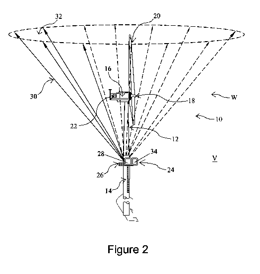
Figure 2 shows a remote sensing system for implementing a method according
to the present invention;
Figure 3 shows a plan view of the remote sensing system shown in Figure 2, in
a first scan geometry configuration;
10 Figure 4 shows a plan view of the remote sensing system shown in
Figure 1, in
a second scan geometry configuration;
Figure 5 shows another remote sensing system for implementing a method
according to the present invention;
Figure 6 shows a plan view of the remote sensing system shown in Figure 5, in
15 a first scan geometry configuration;
Figure 7 shows a plan view of the remote sensing system shown in Figure 5, in
a second scan geometry configuration;
Figure 8 shows another remote sensing system for implementing a method
according to the present invention;
20 Figure 9 shows a plan view of the remote sensing system shown in
Figure 8, in
a first scan geometry configuration;
Figure 10 shows a plan view of the remote sensing system shown in Figure 8,
in a second scan geometry configuration;
Figure 11 shows a flow chart representing a method according to another
25 embodiment of the present invention;
Figure 12 shows a remote sensing system for implementing the method of
Figure 11;
Figure 13 shows a plan view of the remote sensing system shown in Figure 12,
in a first scan geometry configuration;
30 Figure 14 shows a plan view of the remote sensing system shown in
Figure 12,
in a second scan geometry configuration;
Figure 15 shows another remote sensing system for implementing the method
of Figure 11;
Figure 16 shows a plan view of the remote sensing system shown in Figure 15,
in a first scan geometry configuration;
CA 03027610 2018-12-13
WO 2017/216531 PCT/GB2017/051704
31
Figure 17 shows a plan view of the remote sensing system shown in Figure 15,
in a second scan geometry configuration;
Figure 18 shows another remote sensing system for implementing the method
of Figure 11;
Figure 19 shows a plan view of the remote sensing system shown in Figure 18,
in a first scan geometry configuration;
Figure 20 shows a plan view of the remote sensing system shown in Figure 18,
in a second scan geometry configuration;
Figure 21 shows a diagrammatic view of an exemplary remote sensing device
for use in the method of Figure 1, the system of Figures 2 to 4, the system of
Figures 5
to 7, the system of Figures 8 to 10, the method of Figure 11, the system of
Figures 12
to 14, the system of Figures 15 to 17, or the system of Figures 18 to 20;
Figure 22 shows a co-ordinate system illustrating the determination of fluid
velocity; and
Figure 23 shows examples of different scan geometries; and
Figure 24 shows a diagrammatic view illustrating a convergent scan geometry.
DETAILED DESCRIPTION OF THE DRAWINGS
Referring first to Figure 1 of the accompanying drawings, there is shown a
flow
chart representing a method according to an embodiment of the present
invention.
As shown in Figure 1, the first step of the method comprises implementing a
first scan geometry configuration to acquire a first measurement data set.
This first
measurement data set is then processed to determine an improved or optimal
scan
geometry configuration. The measurement configuration of the remote sensing
device
is then adapted by changing the scan geometry configuration of the remote
sensing
device. This information is then fed back and the remote sensing device
operated in
the changed scan geometry configuration.
Beneficially, embodiments of the invention permit an optimal or at least
improved remote sensing measurement campaign to be implemented under changing
conditions by actively adjusting the measurement configuration of the remote
sensing
device during the measurement campaign. This is effected by adapting the scan
geometry configuration of the remote sensing device during the measurement
campaign based on measurement data acquired earlier during the same
measurement
campaign; in contrast to conventional RSDs which offer only a single scan
geometry
configuration during a measurement campaign - typically the default setting of
the
CA 03027610 2018-12-13
WO 2017/216531 PCT/GB2017/051704
32
particular remote sensing device or one which is based on the initial
objectives of the
measurement campaign and projections of prevailing conditions made prior to
commencing the measurement campaign. Embodiments of the present invention may
adapt the configuration of the remote sensing device, and in particular the
configuration
of its scan geometry, during the measurement campaign to match the
circumstances
and conditions in which the measurements are acquired, which may vary
significantly
and repeatedly over time. Embodiments of the present invention thereby
mitigate or
eliminate inaccuracies which may otherwise arise in conventional systems and
techniques due to measurement biases resulting from the, often significant,
periods of
time when measurements obtained are not fit for purpose or are relevant only
for part
of a given measurement campaign.
Referring now to Figure 2 of the accompanying drawings, there is shown a
system 10 for implementing the method shown in Figure 1.
As shown in Figure 2, in the illustrated embodiment the system 10 comprises a
wind turbine system including a wind turbine 12 having a tower 14, a nacelle
16 and a
hub 18 having a plurality of radially extending blades 20. The hub 18 is
operatively
coupled to an electrical generator 22 via a drive shaft (not shown). In use,
the kinetic
energy of wind W impinging on the blades 20 drives rotation of the hub 18
relative to
the nacelle 16, this kinetic energy being transmitted to the electrical
generator 22
where it is converted into electricity.
The system 10 further comprises a remote sensing device 24 which, in the
illustrated embodiment, is disposed on a platform 26 provided around the tower
14 of
the wind turbine 12. It will be recognised, however, that the remote sensing
device 24
may be provided at other suitable locations, such as a remote location, on the
nacelle
16, on the ground or on one or more other turbine (not shown).
The remote sensing device 24 comprises a Lidar device having an optical
source 28 - in the illustrated embodiment a laser source ¨ for transmitting a
probe 30 in
the form of a light beam to a region of interest 32 within the overall
measurement
volume V. The remote sensing device 24 further comprises or is operatively
associated with a receiver 34 - in the illustrated embodiment an optical
antenna ¨ for
detecting the reflected probe 30. Referring now also to Figures 3 and 4 of the
accompanying drawings, the remote sensing device 24 is capable of emitting the
probe
30 along a number of different lines of sight, the available lines of sight
capable of
being emitted by remote sensing device 24 represented in Figure 3 by dashed
lines 36.
As shown in Figure 3, the remote sensing device 24 is initially configured and
operated
CA 03027610 2018-12-13
WO 2017/216531 PCT/GB2017/051704
33
in a first scan geometry configuration to acquire a first measurement data
set, the first
scan geometry configuration comprising a first subset 38 of the lines of sight
36.
Following acquisition of the first data set, an improved or optimal second
scan
geometry configuration is determined from the acquired first data set.
The
determination of the optimal scan geometry configuration may depend on the
specific
objectives of the measurement campaign. For example, upwind data may be
required,
and the scan geometry adjusted to always point upwind as the wind direction
changes
from one period of data acquisition to the next. The direction to the target
volume may
change as the platform rotates, for example, a wind turbine nacelle, in which
case the
scan geometry is adjusted to direct the lines of sight as required. In the
illustrated
embodiment, the second scan geometry configuration is formed by a second
subset 40
of the possible lines of sight 36. The remote sensing device 24 is then
reconfigured
from the first scan geometry configuration as shown in Figure 2 to the second
scan
geometry configuration shown in Figure 4. The new scan geometry is selected
from a
look up table in accordance with the prevailing conditions as measured, or the
values
of azimuth angle and elevation angle could be calculated and a configuration
file
written as required.
The remote sensing device 24 is then operated in the second scan geometry
configuration to acquire a second data set relating to the region of interest
30. In this
embodiment, the determination of the optimum or improved scan geometry
configuration of the remote sensing device 24 is carried out during the
measurement
campaign and more particularly between each data acquisition. However, it will
be
recognised that the determination of the optimum or improved scan geometry
configuration may alternatively be carried out during the measurement campaign
but
only after a selected number of data acquisitions or where the level of
adjustment
determined exceeds a selected threshold.
Referring now to Figure 5 of the accompanying drawings, there is shown
another system 110 for implementing the method shown in Figure 1.
As shown in Figure 5, in the illustrated embodiment the system 110 comprises
a wind turbine system including a wind turbine 112 having a tower 114, a
nacelle 116
and a hub 118 having a plurality of radially extending blades 120. The hub 118
is
operatively coupled to an electrical generator 122 via a drive shaft (not
shown). In use,
the kinetic energy of wind W' impinging on the blades 120 drives rotation of
the hub
118 relative to the nacelle 116, this kinetic energy being transmitted to the
electrical
generator 122 where it is converted into electricity.
CA 03027610 2018-12-13
WO 2017/216531 PCT/GB2017/051704
34
The system 110 further comprises a remote sensing device 124 which, in the
illustrated embodiment, is disposed on a platform 126 provided around the
tower 114 of
the wind turbine 112. It will be recognised, however, that the remote sensing
device
124 may be provided at other suitable locations, such as a remote location, on
the
nacelle 116, on the ground or on one or more other turbine (not shown).
In this embodiment, the remote sensing device 124 comprises a Sodar device
having an acoustic source 128 for transmitting a probe 130 in the form of a
beam to a
region of interest 132 within the overall measurement volume V'. The remote
sensing
device 124 further comprises or is operatively associated with a receiver 134 -
in the
illustrated embodiment an acoustic antenna ¨ for detecting the reflected probe
130.
Operation of the system 110 is similar to that of the system 10 and will be
described with reference to Figures 6 and 7 of the accompanying drawings.
As shown in Figures 6 and 7, the remote sensing device 124 is capable of
emitting the probe 130 along a number of different lines of sight, the
available lines of
sight capable of being emitted by remote sensing device 124 represented in
Figure 6
by dashed lines 136. As shown in Figure 6, the remote sensing device 124 is
initially
configured and operated in a first scan geometry configuration to acquire a
first
measurement data set, the first scan geometry configuration comprising a first
subset
138 of the lines of sight 136. Following acquisition of the first data set, an
improved or
optimal second scan geometry configuration is determined from the acquired
first data
set. The determination of the optimal scan geometry configuration may depend
on the
specific objectives of the measurement campaign. For example, upwind data may
be
required, and the scan geometry adjusted to always point upwind as the wind
direction
changes from one period of data acquisition to the next. The direction to the
target
volume may change as the platform rotates, for example, a wind turbine
nacelle, in
which case the scan geometry is adjusted to direct the lines of sight as
required. In the
illustrated embodiment, the second scan geometry configuration is formed by a
second
subset 140 of the possible lines of sight 136. The remote sensing device 124
is then
reconfigured from the first scan geometry configuration as shown in Figure 6
to the
second scan geometry configuration shown in Figure 7. The new scan geometry is
selected from a look up table in accordance with the prevailing conditions as
measured, or the values of azimuth and elevation angles could be calculated
and a
configuration file written as required. The remote sensing device 124 is then
operated
in the second scan geometry configuration to acquire a second data set
relating to the
region of interest 130. As in the system 10, in the system 110 the
determination of the
CA 03027610 2018-12-13
WO 2017/216531 PCT/GB2017/051704
optimum or improved scan geometry configuration of the remote sensing device
124 is
carried out during the measurement campaign and more particularly between each
data acquisition. However, it will be recognised that the determination of the
optimum
or improved scan geometry configuration may alternatively be carried out
during the
5 measurement campaign but only after a selected number of data
acquisitions or where
the level of adjustment determined exceeds a selected threshold.
Referring now to Figure 8 of the accompanying drawings, there is shown
another system 210 for implementing the method shown in Figure 1.
As shown in Figure 8, in the illustrated embodiment the system 210 comprises
10 a tidal turbine system including a turbine 212 having a tower 214, a
nacelle 216 and a
hub 218 having a plurality of radially extending blades 220. The hub 218 is
operatively
coupled to an electrical generator 222 via a drive shaft (not shown). In use,
the kinetic
energy of fluid flow T, such as the tide or current, impinging on the blades
220 drives
rotation of the hub 218 relative to the nacelle 216, this kinetic energy being
transmitted
15 to the electrical generator 222 where it is converted into electricity.
The system 210 further comprises a remote sensing device 224 which, in the
illustrated embodiment, is disposed on a platform 226 provided around the
tower 214 of
the turbine 212. It will be recognised, however, that the remote sensing
device 224
may be provided at other suitable locations, such as a remote location, on the
nacelle
20 216, on the seabed, a platform or on one or more other turbine (not
shown).
In this embodiment, the remote sensing device 224 comprises an ADCP device
having an acoustic source 228 for transmitting an acoustic probe 230 to a
region of
interest 232 within the overall measurement volume V". The remote sensing
device
224 further comprises or is operatively associated with a receiver 234 - in
the illustrated
25 embodiment an acoustic antenna ¨ for detecting the reflected probe 230.
Operation of the system 210 is similar to that of the systems 10, 110 and will
be
described with reference to Figures 9 and 10 of the accompanying drawings.
As shown in Figures 9 and 10, the remote sensing device 224 is capable of
emitting the probe 230 along a number of different lines of sight, the
available lines of
30 sight capable of being emitted by remote sensing device 224 represented
in Figure 9
by dashed lines 236. As shown in Figure 9, the remote sensing device 224 is
initially
configured and operated in a first scan geometry configuration to acquire a
first
measurement data set, the first scan geometry configuration comprising a first
subset
238 of the lines of sight 236. Following acquisition of the first data set, an
improved or
35 optimal second scan geometry configuration is determined from the
acquired first data
CA 03027610 2018-12-13
WO 2017/216531 PCT/GB2017/051704
36
set. The determination of the optimal scan geometry configuration may depend
on the
specific objectives of the measurement campaign. For example, upstream data
may be
required, and the scan geometry adjusted to always point upstream as the fluid
direction changes from one period of data acquisition to the next. The
direction to the
target volume may change as the platform rotates, for example, a fluid turbine
nacelle,
in which case the scan geometry is adjusted to direct the lines of sight as
required. In
the illustrated embodiment, the second scan geometry configuration is formed
by a
second subset 240 of the possible lines of sight 236. The remote sensing
device 224 is
then reconfigured from the first scan geometry configuration as shown in
Figure 9 to
the second scan geometry configuration shown in Figure 10. The new scan
geometry
is selected from a look up table in accordance with the prevailing conditions
as
measured, or the values of azimuth and elevation angles could be calculated
and a
configuration file written as required. The remote sensing device 224 is then
operated
in the second scan geometry configuration to acquire a second data set
relating to the
region of interest 230. As in the systems 10, 110, in the system 210 the
determination
of the optimum or improved scan geometry configuration of the remote sensing
device
224 is carried out during the measurement campaign and more particularly
between
each data acquisition. However, it will be recognised that the determination
of the
optimum or improved scan geometry configuration may alternatively be carried
out
during the measurement campaign but only after a selected number of data
acquisitions or where the level of adjustment determined exceeds a selected
threshold.
Referring now to Figure 11 of the accompanying drawings, there is shown a
flow chart representing a method according to another embodiment of the
present
invention.
As shown in Figure 11, the first step of the method comprises implementing a
scan geometry configuration comprising multiple scan geometry elements. The
method
then comprises determining, from the received measurement data, one of the
plurality
of scan geometries which is indicative of an improved or optimal scan geometry
at a
first time interval. An output indicative of the improved or optimal scan
geometry at the
first time interval is then provided. The process is repeated for each time
interval.
Beneficially, this embodiment permits an optimal or at least improved remote
sensing measurement campaign to be implemented under changing conditions by
passively adjusting the scan geometry configuration of the remote sensing
device
during the measurement campaign by selecting the optimal scan geometry from
the
plurality of scan geometries available of which the first scan geometry is
comprised,
CA 03027610 2018-12-13
WO 2017/216531
PCT/GB2017/051704
37
during processing of data acquired over multiple time steps; in contrast to
conventional
RSDs which offer only a single scan geometry configuration - typically the
default
setting of the particular remote sensing device - or one geometry
configuration which is
configured prior to commencing a measurement campaign and which is based on
the
initial objectives of the measurement campaign, such that an optimal scan
geometry
cannot be selected with reference to variation of wind conditions during the
measurement campaign.
Figure 12 of the accompanying drawings shows a system 310 for implementing
a method according to Figure 11.
The system 310 comprises a wind turbine system including a wind turbine 312
having a tower 314, a nacelle 316 and a hub 318 having a plurality of radially
extending
blades 320. The hub 318 is operatively coupled to an electrical generator 322
via a
drive shaft (not shown). In use, the kinetic energy of wind W" impinging on
the blades
320 drives rotation of the hub 318 relative to the nacelle 316, this kinetic
energy being
transmitted to the electrical generator 322 where it is converted into
electricity.
The system 310 comprises a remote sensing device 324 which, in the
illustrated embodiment, is disposed on a platform 326 provided around the
tower 314 of
the wind turbine 312. It will be recognised, however, that the remote sensing
device
324 may be provided at other suitable locations, such as a remote location, on
the
nacelle 16, on the ground or on one or more other turbine (not shown).
The remote sensing device 324 comprises a Lidar device having an optical
source 326 - in the illustrated embodiment a laser source ¨ for transmitting a
probe 330
in the form of a light beam over a region of interest 332 within the overall
measurement
volume V". The remote sensing device 324 further comprises or is operatively
associated with a receiver 334 - in the illustrated embodiment an optical
antenna ¨ for
detecting the reflected probe 330.
Referring now also to Figures 13 and 14 of the accompanying drawings, as in
the case of system 10, in the system 310 the remote sensing device 324 is
capable of
emitting the probe 330 along a number of different lines of sight, the
available lines of
sight capable of being emitted by remote sensing device 324 represented in
Figure 13
by dashed lines 336. The remote sensing device 324 is configured and operated
in a
scan geometry configuration to acquire a first measurement data set at a first
time
interval t1, and second measurement data set at a second time interval t2,
this
repeated as often as required to obtain an nth data at a nth time interval tn.
CA 03027610 2018-12-13
WO 2017/216531 PCT/GB2017/051704
38
In this embodiment, the scan geometry configuration comprises a compound
scan geometry encompassing a plurality of scan geometries and, in the
illustrated
embodiment, each of the 1st to nth data sets includes data for the entire
region of
interest 332.
Following data acquisition, each data set is analysed. A first pass of each
data
set determines which one of the scan geometries from the plurality of scan
geometries
is indicative of an improved or optimal scan geometry at each of the given
time
intervals t1...tn. In Figure 13, the optimal or improved scan geometry
configuration
determined after data acquisition for time interval t1 is represented by
subset 338 while
the optimal or improved scan geometry configuration determined after data
acquisition
for time interval t2 is represented by subset 340. Once this is determined, a
second
pass of each data set determines one or more measurement of interest relating
to the
region of interest 332 at the given time interval t1, t2, ...tn from the
selected optimal
subset of scan geometries.
In this embodiment, the determination of the optimum or improved scan
geometry configuration of the remote sensing device 324 is carried out after
data
acquisition, rather than between each data acquisition as in the first
embodiment.
Figure 15 of the accompanying drawings shows another system 410 for
implementing a method according to Figure 11.
The system 410 comprises a wind turbine system including a wind turbine 412
having a tower 414, a nacelle 416 and a hub 418 having a plurality of radially
extending
blades 420. The hub 418 is operatively coupled to an electrical generator 422
via a
drive shaft (not shown). In use, the kinetic energy of wind W" impinging on
the blades
420 drives rotation of the hub 418 relative to the nacelle 416, this kinetic
energy being
transmitted to the electrical generator 422 where it is converted into
electricity.
The system 410 comprises a remote sensing device 424 which, in the
illustrated embodiment, is disposed on a platform 426 provided around the
tower 414 of
the wind turbine 412. It will be recognised, however, that the remote sensing
device
424 may be provided at other suitable locations, such as a remote location, on
the
nacelle 416, on the ground or on one or more other turbine (not shown).
In this embodiment, the remote sensing device 424 comprises a Sodar device
having an acoustic source 426 for transmitting a probe 430 in the form of a
beam over
a region of interest 432 within the overall measurement volume V". The remote
sensing device 424 further comprises or is operatively associated with a
receiver 334 -
CA 03027610 2018-12-13
WO 2017/216531 PCT/GB2017/051704
39
in the illustrated embodiment an acoustic antenna ¨ for detecting the
reflected probe
430.
Referring now also to Figures 16 and 17 of the accompanying drawings, as in
the case of system 310, in the system 410 the remote sensing device 424 is
capable of
emitting the probe 430 along a number of different lines of sight, the
available lines of
sight capable of being emitted by remote sensing device 424 represented in
Figure 16
by dashed lines 436. The remote sensing device 424 is configured and operated
in a
scan geometry configuration to acquire a first measurement data set at a first
time
interval t1, and second measurement data set at a second time interval t2,
this
repeated as often as required to obtain an nth data at a nth time interval tn.
As in the previous embodiment, the scan geometry configuration comprises a
compound scan geometry encompassing a plurality of scan geometries and, in the
illustrated embodiment, each of the 1st to nth data sets includes data for the
entire
region of interest 432.
Following data acquisition, each data set is analysed. A first pass of each
data
set determines which one of the scan geometries from the plurality of scan
geometries
is indicative of an improved or optimal scan geometry at each of the given
time
intervals t1...tn. In Figure 16, the optimal or improved scan geometry
configuration
determined after data acquisition for time interval t1 is represented by
subset 438 while
the optimal or improved scan geometry configuration determined after data
acquisition
for time interval t2 is represented by subset 440. Once this is determined, a
second
pass of each data set determines one or more measurement of interest relating
to the
region of interest 432 at the given time interval t1, t2, ...tn from the
selected optimal
subset of scan geometries. As in the previous embodiment, the determination of
the
optimum or improved scan geometry configuration of the remote sensing device
424 is
carried out after data acquisition, rather than between each data acquisition.
Referring now to Figure 18 of the accompanying drawings, there is shown
another system 510 for implementing the method shown in Figure 11.
As shown in Figure 18, in the illustrated embodiment the system 510 comprises
a tidal turbine system including a turbine 512 having a tower 514, a nacelle
516 and a
hub 518 having a plurality of radially extending blades 520. The hub 518 is
operatively
coupled to an electrical generator 522 via a drive shaft (not shown). In use,
the kinetic
energy of fluid flow T', such as the tide or current, impinging on the blades
520 drives
rotation of the hub 518 relative to the nacelle 516, this kinetic energy being
transmitted
to the electrical generator 522 where it is converted into electricity.
CA 03027610 2018-12-13
WO 2017/216531 PCT/GB2017/051704
The system 510 further comprises a remote sensing device 524 which, in the
illustrated embodiment, is disposed on a platform 526 provided around the
tower 514 of
the turbine 512. It will be recognised, however, that the remote sensing
device 524
may be provided at other suitable locations, such as a remote location, on the
nacelle
5 516, on the seabed, a platform or on one or more other turbine (not
shown).
In this embodiment, the remote sensing device 524 comprises an ADCP device
having an acoustic source 528 for transmitting a sonic probe 530 to a region
of interest
532 within the overall measurement volume V". The remote sensing device 524
further comprises or is operatively associated with a receiver 534 - in the
illustrated
10 embodiment an acoustic antenna ¨ for detecting the reflected probe 530.
Referring now also to Figures 19 and 20 of the accompanying drawings, the
remote sensing device 524 is capable of emitting the probe 530 along a number
of
different lines of sight, the available lines of sight capable of being
emitted by remote
sensing device 524 represented in Figure 19 by dashed lines 536. The remote
sensing
15 device 524 is configured and operated in a scan geometry configuration
to acquire a
first measurement data set at a first time interval t1, and second measurement
data set
at a second time interval t2, this repeated as often as required to obtain an
nth data at
a nth time interval tn.
As in the previous embodiment, the scan geometry configuration comprises a
20 compound scan geometry encompassing a plurality of scan geometries and,
in the
illustrated embodiment, each of the 1st to nth data sets includes data for the
entire
region of interest 532.
Following data acquisition, each data set is analysed. A first pass of each
data
set determines which one of the scan geometries from the plurality of scan
geometries
25 is indicative of an improved or optimal scan geometry at each of the
given time
intervals t1...tn. In Figure 19, the optimal or improved scan geometry
configuration
determined after data acquisition for time interval t1 is represented by
subset 538 while
the optimal or improved scan geometry configuration determined after data
acquisition
for time interval t2 is represented by subset 540. Once this is determined, a
second
30 pass of each data set determines one or more measurement of interest
relating to the
region of interest 532 at the given time interval t1, t2, ...tn from the
selected optimal
subset of scan geometries. As in the previous embodiment, the determination of
the
optimum or improved scan geometry configuration of the remote sensing device
524 is
carried out after data acquisition, rather than between each data acquisition.
CA 03027610 2018-12-13
WO 2017/216531 PCT/GB2017/051704
41
More details relating to the operation and analysis techniques employed in
each
of the above embodiments will now be described with reference to Figures 21 to
24.
As described above, the scan geometry configuration of the remote sensing
devices is used to acquire the measurement data from which characteristics of
the fluid
under investigation can be determined and the scan geometry configuration may
include, amongst other things, the locations and distribution of probe volumes
within
the measurement volume (defined in Cartesian co-ordinates x, y, z); the
orientation of
the probe volumes in terms of the directions along which the probe is emitted
and
detected (defined in terms of azimuth and elevation angles (e, 0)); and the
times at
which the probes are emitted, interact with the fluid under investigation, and
are
subsequently detected (t).
With regard to the location of the probe volumes, in the illustrated
embodiments
the range is determined by measuring the back-scatter of light radiation which
is
reflected by natural aerosols carried by the wind, such as dust, water
droplets,
pollution, pollen, salt crystals or the like. The emissions are back-scattered
and
detected and the Doppler shift imposed on the frequency of the laser emissions
by the
motion of the aerosol particles is analysed to infer characteristics of the
fluid motion.
In addition, the strength of the detected signal can indicate the
concentration of the
aerosol particles at the point where the interaction occurred. Polarisation
effects are
also sometimes observed. The detection of various effects of the interaction
with the
fluid allows investigation of various properties in addition to its motion,
such as the
fluid's composition. The Doppler shift is proportional to the component of the
fluid
velocity vector aligned with the line of sight (LoS) along which the laser
emissions are
directed, that is, the radial velocity. It will therefore depend on the angle
between the
LoS and the direction of the fluid velocity. The fluid velocity vector
components can
thus be inferred from observations of radial velocities along various lines of
sight if the
relationship between the wind velocity vectors witnessed in each probe volume
can be
deduced from the observations. For example, in the simplest case, the wind
velocity
vector can be inferred if each probe volume used in the calculation witnesses
the same
wind velocity vector. This is the case under conditions of uniform flow.
With regard to the orientation of the probe volume, where this is determined
by
the line of sight along which the probe is emitted and the radial distance r
of the probe
alone this line of sight is known, then (r, e, 0) can be stated and (x, y, z)
omitted since
the location and orientation is fully described in polar co-ordinates.
CA 03027610 2018-12-13
WO 2017/216531 PCT/GB2017/051704
42
With regard to the timing information, this may be necessary to take account
of
the dimensions and characteristics of the probe volume itself. For example,
the
response of the probe may not be symmetrical within the probe volume and may
give
rise to effects which must be accommodated using the time information, such as
unsteady features in fluid flow in time and/or where coherent fluid structures
in space
advected through the measurement volume are occurring and are being observed.
Timing information is also important if the measurements in each probe volume
happen
in a sequence rather than simultaneously, for example, as a result of the
acquisition of
measurements along a single line of sight or direction which is then scanned
between a
series of different orientations, rather than along multiple lines of sight
which are
implemented simultaneously.
It should be understood that the embodiment described herein is merely
exemplary and that various modifications may be made thereto without departing
from
the scope of the invention.
For example, while the scan geometries in the illustrated embodiments
comprises divergent scan geometries whereby multiple lines of sight under
consideration may radiate and diverge from the location of a single RSD in
order to
fulfil the requirement for multiple angles relative to the fluid velocity
direction, the scan
geometries may take a number of different forms, as illustrated in Figure 9
and may, for
example, comprise a convergent scan geometry as illustrated in Figure 10,
using single
lines of sight from multiple RSDs which converge on a location of interest
from different
directions. In the case of convergent beams, the relationship between the
fluid velocity
vector witnessed by each probe volume is simplified since the probe volumes
are co-
located and so witness the same velocity vector.