Note : Les descriptions sont présentées dans la langue officielle dans laquelle elles ont été soumises.
FI180574US
SAMPLING ADSORBER, HEAT DESORPTION CHAMBER DEVICE,
SAMPLING APPARATUS AND ANALYZER APPARATUS
TECHNICAL FIELD
Embodiments of the present disclosure relate to analysis technical field, and
particularly to a sampling adsorber, a heat desorption chamber and a sampling
apparatus and an analyzer apparatus.
BACKGROUND
In prior art, there is a request to perform sampling and measurement of a
gas or solid particle material. However, it is needed to further improve
efficiency
on a sampling method or a sampling apparatus. For example, at locations such
as an airport, customhouse, it is needed to perform a rapid and reliable
inspection
on cargo or packages to determine whether a contraband goods is contained or
not.
In addition, when an inspection apparatus in prior art is operated to inspect
a package, it needs to open a package or even damage part of the cargo or
package so as to perform inspection, which is really not convenient for
operation.
It is preferable that an inspection is performed without breaking/opening the
package or damaging the cargo or package.
Thus, it is needed to provide an apparatus to rapidly and reliably sample a
sample to achieve a rapid and accurate field inspection.
SUMMARY
According to an aspect of the present disclosure, there is provided a
sampling adsorber including: an outer barrel, which includes an outer barrel
first
end and an outer barrel second end, and a core located in the outer barrel,
the
1
Date recue/Date Received 2020-11-30
FI180574US
core having a core first end and a core second end, the outer barrel first end
and
the core first end being located at a same side of the sampling adsorber,
wherein,
the core includes an adsorbent portion configured to adsorb a sample and a
core body portion, the adsorbent portion being connected to the core body
portion;
sizes of the outer barrel and the core are formed such that a gap is provided
between the outer barrel and the core to allow external gas/air to enter the
gap
through the adsorbent portion and to subsequently be discharged from a
downstream portion of the gap.
In an embodiment, the outer barrel includes a bypass passage including a
bypass passage inlet and a bypass passage outlet that are separated from each
other spatially, the bypass passage inlet being closer to the outer barrel
first end
than the bypass passage outlet; and
the sampling adsorber further includes an adsorber first inner sealing ring
and an adsorber second inner sealing ring that are located between the core
and
the outer barrel and fixed on an outer circumferential surface of the core,
the
adsorber first inner sealing ring and the adsorber second inner sealing ring
being
spaced apart from each other and configured to allow the core to move within
the outer barrel while keeping seal between the core and the outer barrel, and
being arranged such that, under a first state of the sampling adsorber, the
adsorber first inner sealing ring and the adsorber second inner sealing ring
are
located between the bypass passage inlet and the bypass passage outlet, the
adsorber first inner sealing ring is close to the bypass passage inlet and the
adsorber second inner sealing ring is close to the bypass passage outlet,
thereby
the gas entering the gap through the adsorbent portion is blocked by the
adsorber
first inner sealing ring and flows into the bypass passage inlet, out of the
bypass
passage outlet and entering the downstream portion of the gap.
In an embodiment, the sampling adsorber is brought to a second state by
movement of the core relative to the outer barrel, and under the second state
of
2
Date recue/Date Received 2020-11-30
FI180574US
the sampling adsorber, the adsorber first inner sealing ring is located
between
the bypass passage inlet and the bypass passage outlet and the adsorber second
inner sealing ring is located at a side of the bypass passage outlet away from
the
outer barrel first end, such that the gas flowing out of the bypass passage
outlet
is blocked by the adsorber second inner sealing ring from entering the
downstream portion of the gap.
In an embodiment, the outer barrel includes a desorbed sample passage that
is configured to allow the gas to flow from the adsorbent portion to outside
of
the outer barrel; and
the sampling adsorber further includes an adsorber first inner sealing ring
and an adsorber second inner sealing ring that are located between the core
and
the outer barrel and fixed on an outer circumferential surface of the core,
the
adsorber first inner sealing ring and the adsorber second inner sealing ring
being
spaced apart from each other and configured to allow the core to move within
the outer barrel while keeping seal between the core and the outer barrel, and
being arranged such that, under a first state of the sampling adsorber, the
inlet of
the desorbed sample passage is located between the adsorber first inner
sealing
ring and the adsorber second inner sealing ring and the gas is blocked by the
adsorber first inner sealing ring and the adsorber second inner sealing ring
from
entering the desorbed sample passage.
In an embodiment, the sampling adsorber is brought to the second state by
movement of the core relative to the outer barrel, in which second state the
adsorber first inner sealing ring and the adsorber second inner sealing ring
are
located at a side of the inlet of the desorbed sample passage away from the
outer
barrel first end, such that the gas enters the desorbed sample passage only
through the gap and is discharged from the outer barrel through the desorbed
sample passage.
In an embodiment, the core body portion includes an adsorber sampling
passage having an inlet in communication with the gap and an outlet exposed to
3
Date recue/Date Received 2020-11-30
FI180574US
outside of the outer barrel.
In an embodiment, the sampling adsorber further includes an adsorber third
sealing ring fixed on an outer circumferential surface of the core first end,
the
adsorber third sealing ring being configured to allow the adsorber to move
relative to the outer barrel while keeping seal between the adsorber and the
outer
barrel.
In an embodiment, the sampling adsorber further includes a sampling head
removably mounted to an end of the outer barrel, the sampling head being
configured for scraping an object to be inspected such that the sample is
released
from the object to be inspected.
In an embodiment, the sampling head is made of silicon rubber so as to
adhere the sample to be inspected; and/or the sampling head is provided with
an
adsorbent therein so as to adsorb the sample to be inspected.
In an embodiment, the adsorbent portion is provided with screen mesh
structures at both ends thereof to filter large size particles and the screen
mesh
structures are removably coupled with the adsorbent portion so as to fix an
adsorbent in the adsorbent portion.
In an embodiment, the core body portion second end of the core body
portion opposite to the core body portion first end includes sampling adsorber
T-shaped head at its outer surface, and the outer barrel includes a sliding
groove
on an inner side of the outer barrel second end such that the sampling
adsorber
T-shaped head is slidable in the sliding groove and a movement travel of the
sampling adsorber T-shaped head is defined by the sliding groove, and
under the first state of the sampling adsorber, the sampling adsorber T-
shaped head contacts a first end of the sliding groove, and under the second
state
of the sampling adsorber, the sampling adsorber T-shaped head contacts a
second end of the sliding groove, the second end of the sliding groove being
closer to the core body portion second end than the first end of the sliding
groove.
According to an aspect of the present disclosure, there is provided a heat
4
Date recue/Date Received 2020-11-30
FI180574US
desorption chamber device including a chamber body, the chamber body
defining a heat desorption chamber, wherein the chamber body has a chamber
first end and a chamber second end that is opposite to the chamber first end
and
is open, and the chamber body includes a heat chamber and a cool chamber that
are connected to each other by a thermal isolating disc, wherein the sampling
adsorber as mentioned above is insertable into the cool chamber of the chamber
body through the chamber second end, which is open, of the chamber body of
the heat desorption chamber device;
the heat desorption chamber device further includes a baffle plate and a
baffle plate sealing ring between the baffle plate and the chamber, the baffle
plate sealing ring being configured to allow the baffle plate to be movable
within
the heat chamber of the heat desorption chamber while keeping seal between the
baffle plate and the chamber;
wherein the chamber body includes a carrier gas inlet and a carrier gas
outlet such that under a third state of the heat desorption chamber device is,
the
baffle plate is located at a side of the carrier gas outlet away from the
chamber
first end, and that a carrier gas is allowed to enter the heat desorption
chamber
through the carrier gas inlet and is discharged from the carrier gas outlet.
In an embodiment, the baffle plate is connected to the chamber first end of
the chamber by a spring, wherein the spring is configured such that the baffle
plate is kept by the spring, under no external force, at a side of the carrier
gas
outlet away from the chamber first end and is allowed to move towards the
chamber first end by pressing the spring under an external force, thereby the
baffle plate sealing ring is located at a side of the carrier gas inlet close
to the
chamber first end.
In an embodiment, the heat desorption chamber device further includes a
heating rod which is mounted to the baffle plate and protrudes from the baffle
plate towards the chamber second end.
In an embodiment, the heat chamber includes: a temperature control device
Date recue/Date Received 2020-11-30
FI180574US
which includes a heater configured to heat the heat chamber and a temperature
sensor configured to measure a temperature within the heat chamber; and
a heat insulation portion configured to isolate heat within the heat chamber
from dissipating to outside of the heat desorption chamber device.
According to an aspect of the present disclosure, there is provided a
sampling apparatus including the sampling adsorber as described above and the
heat desorption chamber device as described above, wherein the sampling
adsorber is insertable into the cool chamber of the heat desorption chamber
device through the chamber second end, which is open, of the chamber body of
the heat desorption chamber device, such that the outer barrel first end of
the
outer barrel of the sampling adsorber abuts against the thermal isolating disc
by
means of the outer barrel first sealing ring on an outer circumferential
surface of
the outer barrel first end.
In an embodiment, under a state where the sampling adsorber is inserted
into the cool chamber of the heat desorption chamber device, the heating rod
of
the heat desorption chamber device contacts and applies force onto the
adsorbent
portion of the sampling adsorber, such that the adsorbent portion moves within
the outer barrel until the sampling adsorber T-shaped head is stopped by the
second end of the sliding groove, thereby the sampling adsorber is under the
second state.
In an embodiment, the sampling adsorber is insertable into the heat
chamber of the heat desorption chamber device, such that the adsorbent portion
of the sampling adsorber applies force onto heating rod to move the heating
rod
together with the baffle plate towards the chamber first end of the chamber
body
of the heat desorption chamber device until reaching the third state of the
heat
desorption chamber device; and
wherein the outer barrel first sealing ring on the outer circumferential
surface of the outer barrel first end slides within the heat chamber along an
inner
wall of the heat chamber up to a position between the carrier gas inlet and
the
6
Date recue/Date Received 2020-11-30
FI180574US
carrier gas outlet.
In an embodiment, a stop piece is provided on an outer circumferential
surface of the outer barrel, and the stop piece is configured to, under the
third
state of the heat desorption chamber device, abut against the thennal
isolating
disc of the heat desorption chamber device so as to stop the outer barrel of
the
sampling adsorber from moving towards the first end of the heat desorption
chamber device.
In an embodiment, the sampling adsorber includes a slidable collar
surrounding the outer circumferential surface of the outer barrel, the
slidable
collar being fittable in a notch in the second end of the chamber of the heat
desorption chamber device while allowing the outer barrel to move within the
heat desorption chamber device.
BRIEF DESCRIPTION OF THE DRAWINGS
Figure 1 illustrates a cross section view of a sampling adsorber according
to an embodiment of the present disclosure;
Figure 2 illustrates a cross section view of a sampling adsorber according
to an embodiment of the present disclosure;
Figure 3 illustrates a cross section view of a heat desorption chamber
device according to an embodiment of the present disclosure;
Figure 4 illustrates a cross section view of a configuration, in which the
sampling adsorber is placed in the heat desorption chamber device, according
to an embodiment of the present disclosure, where the sampling adsorber is not
under a sample desorption state; and
Figure 5 illustrates a cross section view of a configuration, in which the
sampling adsorber is placed in the heat desorption chamber device, according
to an embodiment of the present disclosure, where the sampling adsorber is
under the sample desorption state.
7
Date recue/Date Received 2020-11-30
FI180574US
DETAILED DESCRIPTION OF EXEMPLARY EMBODIMENTS
A clear and complete description of technical schemes of
embodiments of the present disclosure will be made by reference to the
drawings. Obviously, the embodiments that are described herein merely
relate to some, not all, of the embodiments of the present disclosure.
Based on the disclosed embodiment herein, all of other embodiments
that are obtained by those skilled in the art without inventive labor
belong to protective scope of the present disclosure.
In the present disclosure, terms such as "first", "second" are
merely used for description, instead of meaning or indicating relative
importance or number of a feature. As such, a feature that is defined by
"first" or "second" may impliedly include one or more the feature. In
the present disclosure, "a plurality of' means two or more unless a
reverse description is made. In this description, orientation terms such
as "left side", "right side" are described with reference to the drawings,
and are not intended to be limitative to the present disclosure.
Hereinafter, a plurality of embodiments of the present disclosure will be
described by reference to the drawings.
Referring to Figure 1, an embodiment of the present disclosure provides a
sampling adsorber, including an outer barrel, which includes an outer barrel
first end and an outer barrel second end, and a core located in the outer
barrel,
the core having a core first end and a core second end and the outer barrel
first
end and the core first end being located at the same side of the sampling
adsorber. In the embodiment, the core includes an adsorbent portion configured
to adsorb a sample and a core body portion, and the adsorbent portion is
connected to the core body portion; sizes of the outer barrel and the core are
formed such that a gap is formed between the outer barrel and the core such
that external gas/air can enters the gap through the adsorbent portion and
subsequently is discharged from a downstream part of the gap.
8
Date recue/Date Received 2020-11-30
FI180574US
As shown in Figure 1, generally, the sampling adsorber includes an outer
barrel 1001 and a core 1002 located in the outer barrel 1001. The core 1002
includes an adsorbent portion 102 and a core body portion. In Figure 1, the
core body portion may be considered as a remaining portion of the core 1002
excluding the adsorbent portion 102. It is noted that the embodiment shown in
Figure 1 is an example of the present disclosure, in which a size of the
adsorbent portion is substantially similar to that of the core body portion.
However, in another embodiment of the present disclosure, the adsorbent
portion and the core body portion may have different sizes. For example, in an
embodiment, a size of the adsorbent portion may be less than that of the core
body portion. In an embodiment, a size of the adsorbent portion may be greater
than that of the core body portion. In an embodiment, the adsorbent portion
and the core body portion may have a shape of cylinder. In an embodiment, the
adsorbent portion and the core body portion may have a shape of cylinder that
has an elliptic section. In an embodiment, the adsorbent portion and the core
body portion may have a shape of cylinder that has a substantially elliptic
section.
In Figure 1, an outer barrel first end of the outer barrel 1001 and a core
first end of the core 1002 are located a left side and an outer barrel second
end
of the outer barrel 1001 and a core second end of the adsorbent core 1002 are
located a right side of Figure 1. A gap is defined between the outer barrel
1001
and the adsorbent core 1002. External gas/air may flow from the left side to
the
right side of Figure 1, that is, the external gas/air firstly enters the
sampling
adsorber through the adsorbent portion 102, and then enters the gap. The gap
in
Figure 1 is located between the outer barrel 1001 and the adsorbent portion
102
and includes a gap portion at an upper side of the adsorbent portion 102 and a
gap portion at a lower side of the adsorbent portion 102. In practice, the gap
may be a gap surrounding the adsorbent portion 102. The downstream portion
of the gap is at right side of Figure 1.
9
Date recue/Date Received 2020-11-30
FI180574US
In an embodiment, the outer barrel 1001 includes a bypass passage 104
including a bypass passage inlet 1041 and a bypass passage outlet 1042 that
are
separated from each other spatially. The bypass passage inlet 1041 is closer
to
the outer barrel first end than the bypass passage outlet 1042. The sampling
adsorber further includes an adsorber first inner sealing ring 1031 and an
adsorber second inner sealing ring 1032 that are located between the core 1002
and the outer barrel 1001 and fixed on an outer circumferential surface of the
core 1002. The adsorber first inner sealing ring 1031 and the adsorber second
inner sealing ring 1032 are spaced apart from each other and are configured to
allow the core 1002 to move within the outer barrel 1001 while keeping seal
between the core 1002 and the outer barrel 1001, and are configured such that,
under a first state of the sampling adsorber, the adsorber first inner sealing
ring
1031 and the adsorber second inner sealing ring 1032 are located between the
bypass passage inlet 1041 and the bypass passage outlet 1042, the adsorber
first inner sealing ring 1031 is close to the bypass passage inlet 1041 and
the
adsorber second inner sealing ring 1032 is close to the bypass passage outlet
1042, thereby the gas entering the gap through the adsorbent portion 102 being
blocked by the adsorber first inner sealing ring 1031 and flowing into the
bypass passage inlet 1041, flowing out of the bypass passage outlet 1042 and
entering the downstream portion of the gap.
The first state of the sampling adsorber may be considered as a sampling
and adsorbing state, that is, when the gas containing a sample to be sampled
passes through the adsorbent portion 102, the sample is adsorbed by the
adsorbent portion while the gas enters the gap through the adsorbent portion
102 and is discharged finally.
In order to increase efficiency of sampling and adsorption, a pump 201
may be provided at the downstream of the gap to establish suction action in
the
gap, promoting entering and passing of the gas through the adsorbent portion
102.
Date recue/Date Received 2020-11-30
FI180574US
In an embodiment, the core body portion includes an adsorber sampling
passage 108, wherein an inlet of the adsorber sampling passage 108 is
communicated with the gap and an outlet thereof is exposed to outside of the
outer barrel 1001. Provision of the adsorber sampling passage 108 is in favor
of collecting the gas that has passed through the sampling adsorber. For
example, when the pump 201 is used, it may be communicated with the outlet
of the adsorber sampling passage 108 to pump and suck the gas. However, it is
not necessary to provide the adsorber sampling passage 108 in other
embodiments.
In an embodiment in which the adsorber sampling passage 108 is
provided, a sealing ring 1034 is provided at the downstream of the inlet of
the
adsorber sampling passage 108, for blocking the gas.
In an embodiment, the sampling adsorber is brought to a second state by
movement of the core 1002 relative to the outer barrel 1001. Under the second
state of the sampling adsorber, the adsorber first inner sealing ring 1031 is
located between the bypass passage inlet 1041 and the bypass passage outlet
1042 and the adsorber second inner sealing ring 1032 is located at a side of
the
bypass passage outlet 1042 away from the outer barrel first end, such that the
gas out of the bypass passage outlet 1042 is blocked by the adsorber second
inner sealing ring 1032 and cannot enter downstream portion of the gap.
Referring to the sampling adsorber in Figure 4, it can be seen that the
adsorber
first inner sealing ring 1031 is located between the bypass passage inlet 1041
and the bypass passage outlet 1042 and the adsorber second inner sealing ring
1032 is located at right side of the bypass passage outlet 1042, such that the
gas
out of the bypass passage outlet 1042 is blocked by the adsorber second inner
sealing ring 1032, thereby substantially sealing the bypass passage. In this
configuration, the gas entering the gap cannot flow to the downstream portion
of the gap, that is, cannot be vented from the right side of the gap.
In an embodiment, the outer barrel 1001 includes a desorbed sample
11
Date recue/Date Received 2020-11-30
FI180574US
passage 110 that allows the gas to flow from the adsorbent portion 102 to
outside of the outer barrel 1001. As shown in Figure 1, the desorbed sample
passage 110 may be disposed at a lower side of the outer barrel 1001, or at
other location of the outer barrel 1001 different from the location of the
bypass
passage 104. During sampling and adsorbing operation of the adsorber, the
desorbed sample passage 110 is blocked, that is, the inlet of the desorbed
sample passage 110 is located between the adsorber first inner sealing ring
1031 and the adsorber second inner sealing ring 1032, such that the gas that
has passed through the adsorbent portion 102 is blocked by the adsorber first
inner sealing ring 1031 and the adsorber second inner sealing ring 1032 and
cannot enter the desorbed sample passage 110. In Figure 1, the inlet of the
desorbed sample passage 110 is located at right side of the adsorber first
inner
sealing ring 1031 and thus the gas in the left portion of the gap is blocked
by
the adsorber first inner sealing ring 1031.
In an embodiment, the sampling adsorber is brought to the second state by
movement of the core 1002 relative to the outer barrel 1001. As for the
sampling adsorber shown in Figure 4 and Figure 5, the adsorber first inner
sealing ring 1031 and the adsorber second inner sealing ring 1032 are located
at a side of the inlet of the desorbed sample passage 110 (shown in Figure 5)
away from the first end of the outer barrel 1001, such that the gas can only
enter the desorbed sample passage 110 through the gap and is discharged from
the outer barrel 1001 through the desorbed sample passage 110.
The second state of the sampling adsorber may be considered as a
desorption state, that is, the sample adsorbed by the adsorbent portion 102 is
desorbed from the adsorbent portion 102 and is discharged from the sampling
adsorber through the desorbed sample passage 110. Under the second state of
the sampling adsorber, the adsorber second inner sealing ring 1032 is located
at
right side of the bypass passage outlet 1042 such that the gas from the bypass
passage outlet 1042 is blocked by the adsorber second inner sealing ring 1032,
12
Date recue/Date Received 2020-11-30
FI180574US
and meanwhile, the adsorber first inner sealing ring 1031 and the adsorber
second inner sealing ring 1032 are located at right side of the inlet of the
desorbed sample passage 110, allowing the gas to enter the desorbed sample
passage 110 through the inlet of the desorbed sample passage 110 and being
discharged from the sampling adsorber. In brief, in this state, the sample
cannot
be passed to right side of Figure 4 or Figure 5 through the gap and can only
be
discharged from the sampling adsorber through the desorbed sample passage
110, to be collected by an analytical apparatus for analysis. According to the
present disclosure, with the above configuration, the sampling adsorber may
achieve switching between the sampling and adsorbing state and the desorption
state through simple movement of the core 1002 and thus achieve a simple and
stable operation.
In the above embodiments, it is not necessary to set the positions of the
bypass passage inlet 1041 and the bypass passage outlet 1042 at the outer
barrel 1001 (along a length direction of the outer barrel 1001) and a position
of
the inlet of the desorbed sample passage 110 (along the length direction of
the
outer barrel 1001) as those shown in Figure 1, and it is also not necessary to
set
a distance between the bypass passage inlet 1041 and the bypass passage outlet
1042 as the distance as shown in Figure 1, as long as they are set such that
the
first state and the second state of the sampling adsorber can be achieved.
For example, as shown in Figure 1, under the first state, an interface
between the adsorbent portion 102 and the core body portion is aligned with
the bypass passage inlet 1041. However, this is not necessary. The embodiment
as shown in Figure 1 is merely one of the optional structures of the sampling
adsorber according to the disclosure.
In an embodiment, the core body portion includes a core body portion
second end, i.e., an end of the core body portion at right side. The core body
portion second end includes a sampling adsorber T-shaped head 107 at its outer
surface. Accordingly, the outer barrel 1001 includes a sliding groove 109
inside
13
Date recue/Date Received 2020-11-30
FI180574US
of the outer barrel second end. The sampling adsorber T-shaped head 107 is
configured to slide in the sliding groove 109 and a movement travel of the
sampling adsorber T-shaped head 107 is defined by the sliding groove 109.
That is, the sampling adsorber T-shaped head 107 can move to a left end of the
sliding groove 109 to leftmost extent and move to a right end of the sliding
groove 109 to rightmost extent, that is, the sampling adsorber T-shaped head
107 can move between the left end and the right end of the sliding groove 109.
Accordingly, when sampling adsorber T-shaped head 107 abuts against the left
end of the sliding groove 109, the sampling adsorber is under the first state;
when the sampling adsorber T-shaped head 107 abuts against the right end of
the sliding groove 109, the sampling adsorber is under the second state.
With the above configuration of matching between the sampling adsorber
T-shaped head 107 and the sliding groove 109, the sampling adsorber may be
brought to the first state by simple operation such as by pushing the core
1002
towards the left side such that the sampling adsorber T-shaped head 107 abuts
against the left end of the sliding groove 109, and may be brought to the
second state by pushing the core 1002 towards the right side such that the
sampling adsorber T-shaped head 107 abuts against the right end of the sliding
groove 109, thereby improving convenience and stability of operation of the
sampling adsorber.
In an embodiment, the sampling adsorber further includes a sampling
head 101 removably mounted to an end of the outer barrel 1001. The sampling
head 101 is configured for scraping an object to be inspected such that the
sample may be separated from the object to be inspected. The sampling head
101 may be connected to a left end of the outer barrel 1001 by a screw thread.
The sampling head 101 may be made of silicon rubber material such that it
may be attached to the left end of the outer barrel 1001 by an adhesion strap.
As shown in Figure 2, the sampling adsorber is brought to close to surface
of an object to be inspected and the sampling head 101 is made to contact and
14
Date recue/Date Received 2020-11-30
FI180574US
scrape the surface of the object to be inspected. Some sample that is
disjunctive
is scraped from the object to be inspected and then enters the adsorbent
portion
102 so as to be adsorbed by the adsorbent portion 102. The sampling head 101
may be made of silicon rubber such that the sample can be cohered to the
sampling head 101. In another embodiment, the sampling head 101 may be
provided with an adsorbing agent such that the sampling head 101 may adsorb
the sample.
It is advantageous to provide the sampling head 101 in that during
sampling, the sampling head 101 of silicon rubber, as an leading end of the
sampling adsorber, may scrape a human body or object to be inspected while a
suction action may be performed by operating a pump 201 so as to adsorb the
sample from the human body or object to be inspected, and the adsorbed
sample may be condensed by extending sampling time period.
In an embodiment, the adsorbent portion 102 may be provided with screen
mesh structures at both ends thereof and the screen mesh structures are
removably coupled with the adsorbent portion 102 so as to fix the adsorbent in
the adsorbent portion 102. For example, the screen mesh structure is matched
with the adsorbent portion 102 by screw thread. This configuration not only
allows the screen mesh structures to be removed so as to conveniently replace
adsorbent within the adsorbent portion 102 but also allows the gas to pass
through the adsorbent portion 102 while avoiding contamination by blocking
powder and dust including great particles outside of the adsorbent portion 102
during sampling.
In an embodiment, the sampling adsorber further includes an adsorber
third sealing ring 1033 fixed on an outer circumferential surface of the core
first end. The adsorber third sealing ring 1033 is configured to allow the
adsorber 102 to move relative to the outer barrel 1001 while keeping seal
between the adsorber 102 and the outer barrel 1001. It is advantageous to
provide the adsorber third sealing ring 1033 in that the gas is blocked by the
Date recue/Date Received 2020-11-30
FI180574US
adsorber third sealing ring 1033 and thus enters the sampling adsorber through
the adsorbent portion 102, instead of entering the sampling adsorber through
the gap between the outer barrel 1001 and the core 1002.
In practice, it is advantageous to provide the pump 201. For example, as
shown in Figure 2, the pump 201 is connected to the outlet of the core body
portion sampling passage 108 by a bellows. The sampling adsorber as shown in
Figure 2 is under the first state (sampling and adsorbing state), the bypass
passage 104 is in a conducting state or on-state and the suction action of the
pump 201 generates a negative pressure in the gap such that the gas at left
side
of the sampling adsorber is sucked into the sampling adsorber. The gas firstly
is sucked into the adsorbent portion 102 and thus the sample contained in the
gas is adsorbed by the adsorbent portion 102. Then the gas enters the
downstream portion of the gap via the bypass passage 104 and subsequently
enters the core body portion sampling passage 108 and pumped away by the
pump 201.
Embodiments of the present disclosure further provide a heat desorption
chamber device including a chamber body. The chamber body defines a heat
desorption chamber. The chamber body has a chamber first end and a chamber
second end that is opposite to the chamber first end and is open. The heat
desorption chamber device further includes a baffle plate 304 and a baffle
plate
sealing ring 3041 disposed between the baffle plate 304 and the chamber body.
The baffle plate sealing ring 3041 is configured to allow the baffle plate 304
to
move in the heat desorption chamber while keeping seal between the baffle
plate 304 and the chamber body. The chamber body includes a carrier gas inlet
301 and a carrier gas outlet 302 such that, when the heat desorption chamber
device is under a third state, the baffle plate 304 is located at a side of
the
carrier gas outlet 302 away from the chamber first end and the carrier gas may
enter the heat desorption chamber from the carrier gas inlet 301 and is
discharged through the carrier gas outlet 302.
16
Date recue/Date Received 2020-11-30
FI180574US
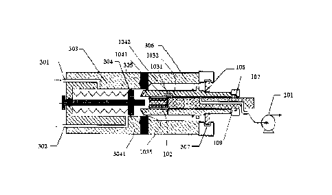
As shown in Figure 3, the heat desorption chamber device is constituted
by a chamber body and the chamber body defines an inner space, i.e., the heat
desorption chamber. Herein, the chamber first end is a left end of the chamber
body and the chamber second end is a right end of the chamber body. As
shown in Figure 3, the right end of the chamber body is open and the heat
desorption chamber may be accessed through the right end of the chamber
body.
The heat desorption chamber device further includes a baffle plate 304
within the chamber body. The baffle plate 304 may slide along a length
direction of the chamber body, that is, the baffle plate 304 may move left and
right as shown in Figure 3. A baffle plate sealing ring 3041 is provided
between
the baffle plate 304 and an inner wall of the chamber body such that the gas
at
the left side of the baffle plate 304 cannot reach the right side of the
baffle
plate.
In an embodiment, the baffle plate 304 is connected to the chamber first
end of the chamber body by a spring, thus the baffle plate 304 is kept at a
side
of the carrier gas outlet 302 away from the chamber first end by the spring
when no external force is applied, and is allowed to move towards the chamber
first end by pressing the spring under an external force, such that the baffle
plate sealing ring 3041 is brought to and located at a side of the carrier gas
inlet
301 close to the chamber first end. In Figure 3, a left side of the baffle
plate
304 is supported by the spring such that the baffle plate 304 is maintained to
be
stable. With this configuration, the baffle plate 304 makes no movement under
no external force, and if the baffle plate 304 is compressed, the baffle plate
304
will be pushed back by the spring to its initial position upon the external
force
being withdrawn, thereby achieving a convenient operation. In other words, in
practice, a user may use the device by inserting an external apparatus and
pull
out the external apparatus after use, without adjusting or operating the
baffle
plate 304 or other components, which results in a simple operation.
17
Date recue/Date Received 2020-11-30
FI180574US
In an example, the heat desorption chamber device is further provided
with a guide rod. The guide rod is coupled to the baffle plate 304,
particularly,
coupled to a left side of the baffle plate 304 (as shown in Figures 3-4). The
guide rod may be a telescopic or retractable, that is, the guide rod itself
may be
retractable so as to allow the baffle plate 304 to move leftwards. When the
baffle plate 304 move to right side, the guide rod extends such that the guide
rod may stabilize the movement of the baffle plate 304. In the embodiment as
shown in Figure 3, the guide rod may be not retractable. The guide rod
penetrates through the left end of the chamber body of the heat desorption
chamber device and may reciprocate in an aperture in the left end of the
chamber body such that the baffle plate 304 may move left and right. A guide
rod sealing ring is provided between the guide rod and an wall of the aperture
in the left end of the chamber body to block communication of the gas between
inside and outside of the chamber body. However, it is noted that the guide
rod
is not indispensable in the present disclosure, that is, in other embodiments
of
the present disclosure, the baffle plate 304 may move left and right within
the
chamber body without any guide rod.
In an embodiment, the heat desorption chamber device further includes a
heating rod 308 which is mounted to the baffle plate 304 and protrudes from
the baffle plate 304 towards the chamber second end. As shown in Figure 3, the
heating rod 308 is disposed at the right side of the baffle plate 304.
The chamber body of the heat desorption chamber device as shown in
Figure 3 may include a heat chamber 303 and a cool chamber 306. The heat
chamber 303 is connected to the cool chamber 306 by a thermal isolating disc
305. The thermal isolating disc 305 may isolate heat between the cool chamber
306 and the heat chamber 303 from exchanging. The baffle plate 304 moves
within the heat chamber 303. In other words, the movement range of the baffle
plate 304 may be defined by the thermal isolating disc 305, that is, the
baffle
plate 304 does not move to right side of the thermal isolating disc 305 when
no
18
Date recue/Date Received 2020-11-30
FI180574US
external force is provided.
It is advantageous to provide the heat chamber 303 and the cool chamber
306. On one hand, the cool chamber 306 may be provided to ensure the sample
adsorbed by the sampling adsorber will not be heated and desorbed from the
sampling adsorber before the sampling adsorber is pushed into the heat
chamber 303 of the heat desorption chamber device; on the other hand, the
cool chamber 306 may be arranged to avoid heat damage to an operator when
operator inserts the sampling adsorber into the heat desorption chamber and/or
onto a drive motor.
In an embodiment, in order to promote heat desorption, the heat chamber
303 includes: a temperature control device including a heater configured to
heat the heat chamber 303 and a temperature sensor configured to measure a
temperature within the heat chamber 303; and a heat insulation portion
configured to isolate heat within the heat chamber 303 from dissipating to
outside of the heat desorption chamber device. For example, the chamber boy
of the heat desorption chamber device may be made of a stainless steel or
copper or other metal that has a good thermal conduction efficiency and
meanwhile, the thermal isolating disc 305 is made of ceramic material to
isolate the heat chamber 303 from the cool chamber 306. In an embodiment,
the heat chamber 303 may be wrapped by a heating film which may heat the
heat chamber 303. A temperature sensor is mounted on outside surface of the
heat chamber 303, to measure the temperature in the heat chamber 303.
Generally, the heat chamber 303 may be controlled at a temperature from 50
Celsius degrees to 300 Celsius degrees. In order to improve heating and heat
preservation effects, the heat chamber 303 may be wrapped by a heat insulation
cotton or other heat insulation layer/material. The heat insulation
layer/material
may increase work efficiency of the heat chamber and save energy, and further
may avoid a user from heat damage by the heat chamber 303 of the heat
desorption chamber device. In other embodiment, the heater may be a heating
19
Date recue/Date Received 2020-11-30
FI180574US
coil or resistance wire heater which surrounds the heat chamber 303 and may
increase the temperature within the heat chamber 303.
Embodiments of the present disclosure further provide a sampling
apparatus including the above sampling adsorber and the heat desorption
chamber device.
The sampling adsorber may be inserted into the cool chamber 306 of the
heat desorption chamber device through the open chamber second end such that
the outer barrel first sealing ring 1035 on the outer circumferential surface
of the
outer barrel first end of the outer barrel 1001 of the sampling adsorber abuts
against the isolating disc 305. According to the sampling apparatus of the
embodiment, the sampling adsorber and the heat desorption chamber device may
be conveniently separated from each other and assembled together such that the
sampling adsorber may be used separately for sampling.
As shown in Figure 4, the sampling adsorber is inserted into the heat
desorption chamber device and the outer barrel first sealing ring 1035 seals
between the outer circumferential surface of the left end of the outer barrel
1001
and the isolating disc 305 of the heat desorption chamber device such that the
gas in a portion of heat desorption chamber at the left side of the isolating
disc
305 cannot enter the right portion of the heat desorption chamber through the
gap between the sampling adsorber and the isolating disc 305.
As shown in Figure 4, when the sampling adsorber is inserted into the cool
chamber 306 of the heat desorption chamber device, the heating rod 308 of the
heat desorption chamber device is in contact with and applies force to the
adsorbent portion 102 of the sampling adsorber, such that the adsorbent
portion
102 moves within the outer barrel 1001 until the sampling adsorber T-shaped
head 107 is stopped by the second end of the sliding groove 109, thereby the
sampling adsorber in under the second state. The core 1002 of the sampling
adsorber is withstood by the heating rod 308 protruded rightwards from the
baffle plate 304. In the embodiment, the sampling adsorber moves leftwards
with
Date recue/Date Received 2020-11-30
FI180574US
the core being withstood by the heating rod 308, that is, the core 1002 moves
rightwards relative to the outer barrel 1001 until the sampling adsorber T-
shaped
head 107 is stopped by the second end of the sliding groove 109.
When the sampling adsorber continues to move leftwards, that is, when the
sampling adsorber is inserted into the heat chamber 303 of the heat desorption
chamber device, the adsorbent portion 102 of the sampling adsorber is stopped
from moving leftwards. In this stage, the core 1002 and the outer barrel 1001
move leftwards together. The adsorbent portion 102 applies force to the
heating
rod 308 such that the heating rod 308 together with the baffle plate 304 moves
towards a left portion of the chamber body ofthe heat desorption chamber
device
until the heat desorption chamber device enters the third state. When the heat
desorption chamber device is in the third state, the outer barrel first
sealing ring
1035 on the outer circumferential surface of the outer barrel first end slides
along
the inner wall of the heat chamber 303 along the heat chamber 303 up to a
position between the carrier gas inlet 301 and the carrier gas outlet 302.
As shown in Figure 5, the baffle plate 304 is located at the left side of the
carrier gas outlet 302 and the carrier gas may enter the heat desorption
chamber
through the carrier gas inlet; meanwhile, the carrier gas is blocked by the
outer
barrel first sealing ring 1035 from passing through a space between the outer
barrel 1001 and the chamber body of the heat desorption chamber device, but is
allowed to enter the adsorbent portion 102 of the sampling adsorber, then pass
through the desorbed sample passage 110, is discharged from the outlet of the
desorbed sample passage 110 and finally is discharged from the carrier gas
outlet
302.
During desorption, the heating rod 308 may be used to directly increase
temperature of the adsorbent portion 102 of the sampling adsorber, promoting
releasing of the sample that is adsorbed by the adsorbent portion 102.
Meanwhile,
the heat chamber 303 is heated by the temperature control device such that
temperature within the heat chamber 303 is maintained at a desired value and
21
Date recue/Date Received 2020-11-30
FI180574US
the sample that is adsorbed and concentrated in the adsorbent portion 102
and/or
the sampling head 101 is desorbed and separated at an increased speed. In this
case, the carrier gas enters from the carrier gas inlet 301, passes through
the
adsorbent portion 102 while carrying the sample away, and finally carries the
sample to pass through the carrier gas outlet 302 to an analyzer apparatus
such
as an ion migration spectroscopy.
In an embodiment of the present disclosure, since the sampling head 101
made of the silicon rubber and adsorbent are at a room temperature during
sampling, it is in favor of sampling and absorption of a sample. Meanwhile,
during desorption, the heat desorption chamber may be controlled at a
temperature range from 80 Celsius degrees to 300 Celsius degrees, so that the
adsorbent that is inserted into the heat desorption chamber may be heated at
an
increased speed and the sample adsorbed in the adsorbent may be easy released
or separated from the adsorbent. Further, the carrier gas that is preheated
may
rapidly mix with the gas containing the separated sample such that the sample
may effectively carried by the carrier gas out of the heat desorption chamber,
and then transferred to an analyzer apparatus, such as an ion migration
spectroscopy/ chromatography-ion migration spectroscopy for measurement.
In an embodiment, a heater may be provided within the baffle plate 304 to
assist in increasing temperature in the adsorbent portion 102.
In an embodiment, a stop piece 105, 131 may be provided on the outer
circumferential surface of the outer barrel 1001. The stop piece 105, 131 is
configured to, under the third state of the heat desorption chamber device,
abut
against the thermal isolating disc 305 of the heat desorption chamber device
so
as to stop the outer barrel 1001 of the sampling adsorber from moving towards
the first end of the heat desorption chamber device. Provision of the stop
piece
105, 131 is advantageous because the stop piece 105, 131 abutting against the
isolating disc 305 indicates that the sampling adsorber is pushed in place and
that the heat desorption chamber device is brought to the third state, so that
a
22
Date recue/Date Received 2020-11-30
FI180574US
heat desorption may start. In addition, in an embodiment, the stop piece 105,
131
may be used as a driven component, for example, a drive motor is provided to
drive the stop piece 105, 131 such that the sampling adsorber moves within the
heat desorption chamber.
In an embodiment, the sampling adsorber includes a slidable collar 106
surrounding the outer circumferential surface of the outer barrel 1001. The
slidable collar 106 may fit in a notch 307 in the second end of the chamber
body
of the heat desorption chamber device while allowing the outer barrel 1001 to
move within the heat desorption chamber device.
In the present disclosure, a plurality of sealing rings are provided and may
be made of high-temperature resistant fluoroelastomer. These rings may be
replaceable.
In embodiments of the present disclosure, the adsorbent in the adsorbent
portion 102 may be adapted to active carbon or TenaxTm-TA.
In embodiments of the present disclosure, the pump 201 may be used and
may be chosen as a type of KNFTM NMP 015B.
Although some embodiments according to a general concept of the present
disclosure have been revealed and described, it is understood that these
embodiments may be modified without departing the principle and spirits of the
present disclosure. The scope of the present disclosure is defined by the
claims
and their equivalents.
23
Date recue/Date Received 2020-11-30