Note : Les descriptions sont présentées dans la langue officielle dans laquelle elles ont été soumises.
CA 03028593 2018-12-19
WO 2018/002891 PCT/IB2017/053950
1
A method for estimating the travel time of a vehicle based on the
determination of the state
of the vehicle
FIELD OF THE INVENTION
The present invention relates to the automotive sector and specifically to the
technical field
of onboard devices for detecting data relating to the motion and driving
parameters of a
vehicle.
Specifically, the invention relates to a method for estimating the travel time
of a vehicle
based on the determination of the state of the vehicle according to the
preamble of claim 1.
STATE OF THE ART
Onboard detection devices are known, in particular for the real-time
acquisition and remote
transmission of motion and driving parameters of a vehicle, which not only
contribute to
the operation of onboard systems for driving assistance but are indispensable
for the
functionality of other auxiliary systems, including, for example, the
vehicle's surveillance
systems and dynamics recording systems, such as systems used in anti-theft
devices, in
monitoring devices for vehicles belonging to a fleet or in devices, known as
black boxes,
for detecting traffic offenses or road accidents dynamics, such as for law
enforcement or
insurance companies.
Typically, a system for monitoring and recording the dynamics of use of a
vehicle is
provided to detect the vehicle's driving conditions (driving speed, overall
driving time,
engine speed) in view of transmitting them to a remote analysis station. The
data may be
transferred periodically to the analysis station via an onboard communication
system or
simply recorded to an inviolable storage media available onboard the vehicle
from where
the data may be retrieved later, for example, when the vehicle is subjected to
a scheduled
periodic maintenance intervention.
In both cases described above, the surveillance system is designed to record,
without
CA 03028593 2018-12-19
WO 2018/002891 PCT/IB2017/053950
2
distinction and continuously, every driving event and every interval of
inactivity of the
vehicle.
The state of the vehicle, that is, the condition of activity (in operation) or
inactivity of the
vehicle's engine, is important information because it is related to the
vehicle's use or non-
use events that represent important data in checking the conditions of use of
a vehicle in
the long run, for example in checking the operation of vehicles belonging to a
fleet. In fact,
in the event that the vehicle engine is in operation, it may be deduced that
the vehicle is
running ('running' meaning a driving condition of the vehicle, including
temporary stops,
but excluding prolonged parking) while in the case wherein the engine of a
vehicle is not in
operation it may be deduced that the vehicle is parked.
There are vehicles that from their production integrate onboard devices for
the detection of
motion and driving parameters to determine the state of the vehicle by means
of a physical
link with the ignition and key start switch device or the CAN bus of the
vehicle. If these
devices are not provided at the time of the vehicle's production, or if the
vehicle is not
equipped with a conventional ignition and key start switch device, it is not
always possible
or convenient (in terms of difficulty and reliability of the intervention) to
make use of a
physical link with the key signal or the CAN bus to determine the vehicle's
state.
The detection of the start and the end of a vehicle trip, i.e. the
determination of the vehicle
travel time, is important information for certain applications. In some cases,
such as when
calculating the distance traveled by the vehicle, it is not important to know
whether this
distance has been traveled on a single trip or over two or more separate
trips, provided that
there is no loss of travel information as a result of the erroneous
subdivision of a trip or
erroneous merging of multiple trips. In other cases, particularly in the
provision of vehicle
fleet management services, accurate tracking of the start and the end of a
trip is an essential
aspect. The likelihood that a single trip will be treated as two separate
trips, or that two
separate trips will be treated as a single trip, is considered a primary
performance indicator
for assessing the efficiency and reliability of a control service of the use
of a vehicle
carried out by the use of onboard devices for detecting data relating to the
motion and
driving parameters of a vehicle.
CA 03028593 2018-12-19
WO 2018/002891
PCT/IB2017/053950
3
Conventionally, the start of a trip corresponds to the transition from an
inactive engine
state or a vehicle-at-rest state (hereinafter, OFF state) to an active engine
state or a running
vehicle state (hereinafter, ON state), which may be determined by detecting a
transition
between corresponding states of the ignition and key start switch device of
the vehicle.
The end of a trip, on the contrary, corresponds to the transition from an
active engine state
or a running vehicle state (ON state) to an inactive engine state or a vehicle-
at-rest state
(OFF state), which may be determined in a similar way.
The start and end of a trip may be accurately detected by means of onboard
devices for
detecting data relating to the motion and driving parameters of the vehicle,
that are
physically connected to a node of the vehicle's electrical system where there
is a voltage if,
and only if, the state of the ignition and startup shutdown switch device is
indicative of an
active engine or running vehicle state. Erroneous determinations of the
vehicle's state may
be due to human errors in the installation of the onboard device when the
physical
connection is made to a node of the vehicle's electrical system where the
voltage value
detected does not follow the state of the ignition and start switch device.
However, there are cases where onboard devices are installed that do not have
a physical
connection with the ignition and start switch device, because the vehicle
installation is
simpler or one wants to avoid possible operator errors when connecting to the
vehicle's
electric system. In this type of device, the state of the vehicle is
determined (estimated) by
detecting the movement of the vehicle or the voltage that is established
across an electric
charge accumulator assembly (battery) of the vehicle, used for starting the
vehicle's
thermal engine and/or for powering the vehicle's accessory devices and
rechargeable by
means of the kinetic energy of the engine.
The detection of a voltage value across the accumulator assembly above a known
voltage
value across the accumulator assembly at rest and the determination of the
movement of a
vehicle provide in combination reliable indicators of the state of the
vehicle. However, the
absence of the same indications does not allow one to deduce with certainty
that the
CA 03028593 2018-12-19
WO 2018/002891
PCT/IB2017/053950
4
vehicle is inactive or at rest.
In fact, when a vehicle stops its operation for a short period of time, for
example in respect
of road signs or in traffic conditions or a traffic jam, the ignition and
start switch remains
in the driving condition, i.e. the vehicle is effectively in use, although
signs of thermal
engine activity may not be present. The vibrations of the thermal engine under
travel stop
conditions may be too small to be detected by vehicle dynamics sensors or may
not be
present at all when the vehicle is equipped with a so-called start/stop
mechanism so that
the thermal engine stops working when the vehicle is stationary for a short
period of time,
then resumes it when it starts travelling again.
SUMMARY OF THE INVENTION
The object of the present invention is to provide a method for accurately
determining the
travel time using an onboard device without physical connection to the
ignition and start
switch device of the vehicle, in particular a method for resolving the
disadvantages
described above.
According to the present invention, this object is achieved by a method for
determining the
travel time having the features recited in claim 1.
Particular embodiments are the subject of the dependent claims, the content of
which is to
be understood as an integral part of the present description.
A further subject of the invention is an onboard device for detecting data
relating to the
motion and driving parameters of a vehicle and a computer program or group of
programs
executable by a processing system of an onboard device, as claimed.
In summary, the present invention is based on the principle of verifying
whether the
determination of the state of a vehicle, upon which the determination of the
start or the end
of a trip depends, obtained indirectly, for example by analyzing the voltage
value that
establishes across an accumulator assembly of a vehicle, by analyzing the
vehicle
CA 03028593 2018-12-19
WO 2018/002891 PCT/IB2017/053950
dynamics data detected by accelerometer and/or gyroscopic sensors, or by
analyzing the
positioning data acquired by a geographical positioning system of the vehicle,
is
unchanged for a predetermined hysteresis time interval having the aim of
filtering any
possible anomalous events of detection of a spurious transition - because it
is excessively
short - from an active engine state or running vehicle state to an inactive
engine state or
vehicle-at-rest state, or vice versa.
Advantageously, an optimal hysteresis time interval is determined by an
analysis of the
error probabilities depending upon a selection of a hysteresis time interval.
Further features and advantages of the invention will be described in greater
detail in the
following detailed description of one embodiment thereof, given by way of non-
limiting
example, with reference to the accompanying drawings concisely described in
the
subsequent paragraph.
BRIEF DESCRIPTION OF THE FIGURES
- Figure 1 is a schematic representation of the context of application of the
present
invention.
Figure 2 is a schematic representation of a coupling configuration onboard a
vehicle
of a device for detecting data relating to the motion and driving parameters
of a vehicle by
means of a physical link to the ignition and key start switch device of the
vehicle,
according to the prior art.
Figure 3 is a functional block diagram of an illustrative, non-limiting
embodiment
of an onboard device for detecting data relating to the motion and driving
parameters of a
vehicle coupled to an electric charge accumulator assembly of the vehicle
according to the
invention.
Figure 4 is a diagram showing an illustrative trend over time of the voltage
that
establishes across an accumulator assembly used for starting a vehicle's
thermal engine
and/or for powering the vehicle's accessory devices and rechargeable by means
of the
kinetic energy of the engine, according to the aforementioned conditions.
Figures 5, 6 and 7 are graphs representative of the probabilities of events on
the
SUBSTITUTE SHEET (RULE 26)
CA 03028593 2018-12-19
WO 2018/002891 PCT/IB2017/053950
6
basis of the optimization of the determination of the travel time according to
the present
invention.
DETAILED DESCRIPTION
Figure 1 shows the context of application of the present invention.
In figure 1, a generic vehicle is indicated at V, such as a private car or a
vehicle belonging
to a fleet of company vehicles. The vehicle V is equipped with a thermal
engine E and an
electric charge accumulator assembly, known simply as a battery, indicated at
B, which
controls the startup of the thermal engine and/or the power supply of the
vehicle's
accessories such as the lighting devices L, and is rechargeable by means of
the kinetic
energy of the engine, typically by means of an alternator A.
An onboard device for detecting data relating to the motion and driving
parameters of the
vehicle, in particular for the real-time acquisition and remote transmission
of said data, is
indicated at U. This device is arranged for processing data relating to motion
and driving
parameters of the vehicle and for transmitting said data to a central remote
unit C, for
example through a public telecommunication network N.
By way of example and for the objects of the present invention, the data
relating to the
motion and driving parameters of the vehicle are data indicative of the travel
time of the
vehicle. The travel time, calculated from a detected travel start time to a
detected travel end
time, is a useful item of data - for example - for checking the conditions of
use of a vehicle
and possibly for the provision of various services related to the use of a
vehicle.
Conventionally, the travel start time is detected at a transition of the state
of the vehicle
from an inactive or rest state (hereinafter referred to as OFF) to a condition
of activity or
running (hereinafter referred to as ON). Likewise, the travel end time is
detected at a
transition of the state of the vehicle from an active or running state (ON) to
an inactive or
rest state (OFF).
Figure 2 shows a typical configuration of the prior art of a coupling on board
a vehicle of a
CA 03028593 2018-12-19
WO 2018/002891 PCT/IB2017/053950
7
device for detecting data relating to motion and driving parameters of the
vehicle in order
to determine the state of the vehicle.
In the known configuration, the onboard device U is physically connected
through
dedicated wiring to an ignition and key start switch device K of the vehicle
or to a similar
node of the electrical system of the vehicle wherein an electrical voltage is
present if, and
only if, the vehicle key is turned to the activation position, and the vehicle
(the engine and
its accessories) is electrically powered by the charging battery.
Figure 3 shows an illustrative block diagram in greater detail of an onboard
device U
according to the invention in the coupling configuration on board the vehicle
of the present
invention.
The onboard device U includes a microprocessor 10 arranged for the acquisition
and
processing of data relating to the motion and driving parameters of the
vehicle, acquired
through an acquisition section, for example comprising a microcontroller 12
connected to a
geographical positioning system 20, shown in the figure in association with
its antenna 22,
to a vehicle dynamics detection system 24, for example a system including one
or more
sensors such as position, tilt or acceleration sensors, arranged to provide
accurate
information on the positioning and orientation of the vehicle in space and on
its
displacement dynamics, and to a communication module 26, shown in the figure
in
association with the relative antenna 28, adapted to exchange data to and from
the
telecommunication network N.
The onboard device U also includes an input and output interface 30 connected
to the
microcontroller 12 for connection to an onboard communication network of the
vehicle, as
in a purely non-limiting and non-exclusive example a CAN network, and to
remote
communication modules 32, 34, such as Wi-Fi or Bluetooth communication
modules, for
connecting the microprocessor 10 to auxiliary devices, for example used to
authenticate the
vehicle's driver and/or to inhibit the startup of the vehicle when the driver
is not
authenticated.
CA 03028593 2018-12-19
WO 2018/002891 PCT/IB2017/053950
8
The figure also shows a physical connection module 36 for connection to an
electric charge
accumulator assembly B of the vehicle, capable of bringing to the
microprocessor a signal
indicative of the voltage value that is established across the accumulator
assembly.
For the sake of completeness in representation, the accumulator assembly B is
shown in
conjunction with a charge alternator A, driven by the vehicle's thermal engine
E, and in
conjunction with some illustrative loads such as an instrument panel I of the
vehicle or the
headlights L of the vehicle.
Figure 4 is a diagram showing an illustrative trend in time of the voltage
that is established
across an accumulator assembly B when it is used for starting a vehicle's
thermal engine
and/or for powering the vehicle's accessory devices, and is rechargeable by
means of the
kinetic energy of the engine E by means of the alternator A.
For an accumulator assembly having a nominal voltage VNOM of 12 V, the voltage
value
present across the assembly in a state of inactivity or rest of the vehicle is
substantially
equal to or slightly above the nominal voltage VNOM. When starting the
vehicle's thermal
engine, a large amount of electrical energy is drained from the accumulator,
and for a
limited time, on the order of a fraction of a second, a sharp voltage drop is
experienced
across it, on the order of several volts, until reaching the value VSTART.
Subsequently, when
the vehicle is running and the kinetic energy of the thermal engine is used to
recharge the
accumulator assembly via the alternator A, the value of the voltage across the
accumulator
is higher than the nominal value, e.g. on the order of about 2 volts, the
average value being
indicated as VMAR, and affected by noise, until the vehicle's engine shuts off
and returns to
a state of inactivity (or rest), whereby the voltage across the accumulator
decreases to the
nominal value VNOM.
The detennination of the travel time of a vehicle is carried out by measuring
the time
between the start of travel, corresponding to the transition from an inactive
engine state or
a vehicle-at-rest state (hereinafter, OFF state) to an active engine state or
a running vehicle
state (hereinafter, ON state), and the end of travel, corresponding instead to
the transition
from an active engine state or running vehicle state (ON state) to an inactive
engine state or
CA 03028593 2018-12-19
WO 2018/002891 PCT/IB2017/053950
9
a vehicle-at-rest state (OFF state).
According to the invention, a transition from an inactive engine state or a
vehicle-at-rest
state (OFF state) to an active engine state or a running vehicle state (ON
state) is
recognized as a trip start event if it is determined that the active engine
state or running
vehicle state is maintained unaltered for a predetermined hysteresis time
interval.
Likewise, a transition from an active engine state or a running vehicle state
(ON state) to
an inactive engine state or a vehicle-at-rest state (OFF state) is recognized
as an end of
travel event if it is determined that the inactive engine state or vehicle-at-
rest state is
maintained unaltered for a predetermined hysteresis time interval.
The predetermined hysteresis time interval may have different values for each
transition.
A possible error in determining the travel time that the present invention
aims to avoid is
related to the division of an actual single trip into a number of separate
trips.
This error may occur when a vehicle stops running for a period of time longer
than the
hysteresis time interval, although its real state is ON for the whole period.
This is the case,
for example, for traveling vehicles that temporarily stop running in traffic,
even by turning
off the engine (start/stop system). In this case, a transition from the ON
state to the OFF
state may be erroneously detected even if it has not occurred. A subsequent
transition from
the OFF state to the ON state will be detected as soon as the vehicle's
movement or engine
activity is subsequently resumed. Therefore, an actual single trip (whereby,
for example,
the ignition and start key has never really been changed to the OFF position)
is considered
instead as two separate trips.
Another possible error in determining the travel time that the present
invention aims to
avoid is related to the combining of a plurality of actual separate trips into
a single trip.
This error may occur when a vehicle actually stops its operation and ends a
trip (whereby,
for example, the ignition and start key is actually moved to the OFF position)
but remains
CA 03028593 2018-12-19
WO 2018/002891 PCT/IB2017/053950
at rest for a period of time less than the hysteresis time interval.
In this case, a transition from the ON state to the OFF state - indicating the
end of a trip -
and a subsequent transition from the OFF state to the ON state - indicating
the start of a
separate trip - may erroneously be detected but not considered valid even
though it actually
took place. Therefore, two actual separate consecutive trips are considered as
a single trip.
If the hysteresis time interval is set to a very low value, for example a few
seconds, the
frequency of errors in recognizing separate trips instead of an actual single
trip will be very
high since potentially any brief stop of the vehicle's operation would result
in the
determination of a transition from the ON state to the OFF state. Conversely,
the frequency
of errors in recognizing a single trip instead of actual separate trips will
be greatly reduced,
as potentially only separations of a few seconds between separate trips (rare
in practice)
may be erroneously ignored.
If the hysteresis time interval is set to a very high value, for example
several minutes, the
frequency of errors in recognizing separate trips instead of an actual single
trip will be
much reduced since potentially only prolonged stops of the vehicle's operation
would
result in the determination of a transition from the ON state to the OFF
state. Conversely,
the frequency of errors in recognizing a single trip instead of actual
separate trips will be
greatly increased as, potentially, separations of a few seconds between actual
separate trips
(rare in practice) may be erroneously ignored.
The following discusses the evaluation of the probability of occurrence of the
above-
described errors as a function of the hysteresis time interval in order to
identify an optimal
hysteresis time interval.
In the following description, a "temporary stop" of the vehicle shall mean a
stop occurring
without disabling the vehicle's engine, such as a stop of the vehicle's travel
at a traffic
light or in a traffic jam. Short and very slow movements, such as the
movements needed
when a vehicle advances in a traffic jam, are considered equivalent to
temporary stops
since the actual movement of the vehicle is substantially negligible.
Furthermore, a
CA 03028593 2018-12-19
WO 2018/002891 PCT/IB2017/053950
11
"definitive stop" of the vehicle shall mean a vehicle stop carried out in
conjunction with
engine deactivation, such as parking the vehicle. A temporary stop is not the
end of a trip;
a definitive stop instead is the end of a trip.
Pr (t <T I s = final) indicates the conditional probability that a definitive
stop (s = final)
will last for a time interval t shorter than a predetermined reference time
interval T.
Pr (t <T s = temporary) indicates the conditional probability that a temporary
stop (s =
temporary) will last for a time interval t shorter than a predetermined
reference time
interval T.
Pr (s =final. t <T) indicates the joint probability that a stop is definitive
(s = final) and that
it will last for a time interval t shorter than a predetermined reference time
interval T.
Pr (s = temporaty, t <T) indicates the joint probability that a stop is
temporary (s =
temporary) and that it will last for a time interval t shorter than a
predetermined reference
time interval T.
Pr(Eb, T) indicates the probability that an actual single trip will be
subdivided into a
plurality of (two) separate trips as a function of a predetermined hysteresis
time interval T
in the execution of an algorithm for determining the state of the vehicle.
Pr(E, T) indicates the probability that a plurality of (two) actual separate
trips will be
merged into a single trip as a function of a predetermined hysteresis time
interval T in the
execution of an algorithm for determining the state of the vehicle.
Pr(E, T) indicates the probability that an actual single trip will be
subdivided into a
plurality of (two) separate trips and that a plurality of (two) actual
separate trips will be
merged into a single trip as a function of a predetermined hysteresis time
interval T in the
execution of an algorithm for determining the state of the vehicle.
According to the invention, a set of travel data acquired by a plurality of
vehicles is
CA 03028593 2018-12-19
WO 2018/002891 PCT/IB2017/053950
12
considered, for example, more than 1,000 vehicles and preferably more than
10,000
vehicles, for a number of trips made exceeding 100,000 and preferably over
1,000,000,
wherein said travel data are representative of the duration of trips made by
the vehicles and
the duration of the temporary stop and final stop intervals. For example, said
travel data is
acquired from onboard devices for detecting data relating to motion and
driving parameters
of a vehicle of the type described in the present invention, preferably
associated with the
ignition and key start switch device of the vehicles on which they are
installed.
A large amount of travel data allows one to have a significant set of samples
to estimate
the distribution of temporary stop events during a trip.
Using the optimization techniques of interpolation of statistical
distributions, the
probability functions Pr(t <T I s = final) and Pr(t <T I s = temporary) are
determined for
hysteresis time interval T values between 0 and a predetermined upper limit.
These are
shown in figure 5. Curve A shows that the probability that a definitive stop
event will last
less than the predetermined upper limit of the hysteresis interval is very
low, essentially
between 2% and 8% based on experimental data obtained by the inventors. Curve
B shows
that the probability that a temporary stop event will last less than the
predetermined upper
limit of the hysteresis interval is very high, substantially above 30% for
relatively small
hysteresis time interval values and reaching 90% for higher values of the
hysteresis time
interval.
From the same data are derived the corresponding joint probabilities Pr (s =
final, t <T) and
Pr (s = temporary, t <T), these same also determined for values of the
hysteresis time
interval T between 0 and said predetermined upper limit, shown in figure 6.
By way of example, figure 6 shows with curve A the probability that a stop
event will last
less than the predetermined upper limit of the hysteresis time interval and
that it is a
definitive stop event. For example, based on experimental data obtained by the
inventors
such probability is about 3.6%. Figure 6 also shows with curve B the
probability that a stop
event will last less than the predetermined upper limit of the hysteresis time
interval and
that it will be a temporary stop event. For example, such probability is
approximately 5.3%
CA 03028593 2018-12-19
WO 2018/002891 PCT/IB2017/053950
13
based on experimental data obtained by the inventors.
The joint properties allow one to estimate the probability of error Pr(Eb, T),
Pr(E,,, T) and
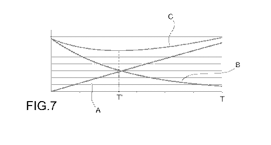
Pr(E, T), shown in figure 7.
Figure 7 shows that for low values of the hysteresis time interval (tending to
zero) the
probability of erroneously merging two actual separate trips tends to 0 (curve
A), while the
probability of erroneously subdividing an actual single trip into two separate
trips is high
(curve B), as it depends on the fact that each temporary stop determines the
interpretation
of a subdivision of an actual trip into separate trips if the hysteresis time
interval is set to a
very low value.
On the other hand, a high value of the hysteresis time interval would result
in the
recognition of a smaller number of subdivisions of individual actual trips
(for example, less
than 1% for a hysteresis time interval based on experimental data obtained by
the
inventors), however, the number of actual separate trips erroneously merged
into a single
trip would be relatively high.
The total error probability is shown in figure 7 by curve C, which considers
both errors.
The minimum value of this curve allows one to determine the optimal hysteresis
time
interval, indicated by T' in the figure. The same corresponds, for example, to
an optimal
time interval, which entails a minimum error probability.
Curve C of figure 7 is a significant indication for configuring the optimal
hysteresis time
interval in a method for determining the travel time of a vehicle based on the
use of an
onboard device adapted to indirectly determine the state of a vehicle, for
example based on
an analysis of the voltage value that is established across an accumulator
assembly of the
vehicle, an analysis of vehicle dynamics data detected by accelerometer and/or
gyroscopic
sensors, or an analysis of positioning data acquired by a geographical
positioning system of
the vehicle.
When the importance of an error in recognizing separate trips in the case of
an actual
CA 03028593 2018-12-19
WO 2018/002891 PCT/IB2017/053950
14
single trip is the same as the importance of an error in recognizing a single
trip in the case
of actual separate trips, a hysteresis time interval value corresponding to
the minimum of
the probability curve that an actual single trip is subdivided in a plurality
of (two) separate
trips and that a plurality of (two) actual separate trips is merged into a
single trip is an
optimal hysteresis interval value.
When, by virtue of the intended purpose of recognizing a trip, the importance
of an error
relating to the subdivision of an actual single trip is greater than the
importance of an error
concerning the merging of actual separate trips, then the hysteresis time
interval may be
increased at the expense of a greater probability of an error in merging
actual separate
trips. Conversely, when the importance of an error in the merging of actual
separate trips is
greater than the importance of an error in the subdivision of an actual single
trip, the
hysteresis time interval may be reduced at the expense of a higher probability
of an error in
subdividing individual actual trips.
It is worth noting that in the implementation of a method for estimating the
travel time of a
vehicle of the present invention, the application of a hysteresis time
interval does not
necessarily occur by an onboard device for detecting data relating to the
motion and
driving parameters of a vehicle. In an alternative embodiment, the onboard
device may be
programmed to apply a very short hysteresis time interval, near or equal to
zero, and a
hysteresis time interval may be applied to data processing that occurs at the
central remote
unit. This possibility provides operational flexibility over having a
hysteresis time interval
set in an onboard device, since it allows said hysteresis time interval to be
modified
according to the intended use of a specific onboard device or of the vehicle
on which a
device is installed, for example, as a function of the individual vehicle, its
driver and
possibly even over the time.
Naturally, without altering the principle of the invention, the embodiments
and the details
of implementation may vary widely with respect to what is described and
illustrated purely
by way of non-limiting example, without thereby departing from the scope of
protection of
the invention defined by the appended claims.