Note : Les descriptions sont présentées dans la langue officielle dans laquelle elles ont été soumises.
CA 03030583 2019-01-07
WO 2018/200741 PCT/US2018/029461
TAMPER-RESISTANT CLOSURE ASSEMBLY
BACKGROUND
The inventive subject matter disclosed herein, which encompasses various
embodiments
and permutations of inventive features, generally relates to tamper-resistant
closure assemblies
for storing cigarettes and the like.
Generally speaking, a cigarette is a cylinder of thin paper or herbaceous leaf
filled with
finely cut herbaceous material for smoking. When used, a distal end of the
cigarette is ignited
causing the finely cut herbaceous material to smolder. Smoke from the
smoldering herbaceous
material can be ingested by a user, as by inhaling smoke through the user's
mouth from an
opposed proximal end (sometimes referred to as a "suction-end"). In some
instances, a cigarette
holder may also be used to retain, or hold, the suction end for use. Some
modern, manufactured
cigarettes include a filter positioned proximally of the herbaceous fill
material as to remove one
or more products of combustion from the smoke before ingestion by a user.
Examples of
herbaceous fill material include, without limitation, leaves and/or flowers of
a variety of plants,
for example, blue lotus, sage, damiana, mullein, catnip, tobacco, cloves, etc.
The cigarettes can
also contain mixtures of different herbs.
Cigarettes may be hand-rolled by the user with rolling papers, or they may be
machine-
rolled. A cigarette can vary in size, e.g., super slim size (about 120 mm in
length and about 4.8
mm in diameter), standard or demi slim size (about 84 mm in length and about
5.2 mm in
diameter), or king size (about 84 mm in length and about 7.9 mm in diameter).
Despite the common use of cigarettes, there has been a lack of a safe,
effective, and
convenient way for the storage of new or partially consumed cigarettes. For
example, many
cigarette containers are not child-safe such that a child may incidentally
open the container and
suffers an adverse reaction to the consumption of cigarette. Many cigarette
containers are not
tightly sealed. Accordingly, the odor of the cigarette may escape the
container, and the moisture
can also get into or escape from the container, affecting the moisture content
and freshness of the
cigarette, and compromising its taste and effects. Moreover, for most
cigarette containers, the
stored cigarettes are loosely packed and not secured. Accordingly, when a
person carries such a
container in travel or accidentally drops the container on the floor, the
stored cigarettes may
dangle inside or hit the walls of the container, causing the cigarettes to
disintegrate. Further,
currently there is no effective solutions for the storage of partially
consumed cigarettes. In
addition, most cigarette containers are not designed for user convenience. For
example, a user
1
CA 03030583 2019-01-07
WO 2018/200741
PCT/US2018/029461
cannot use it as a temporarily holder for a partially consumed cigarette when
he temporarily
pauses smoking. Or a user may not find other accessories necessary for smoking
such as a
lighter, a rolling paper, a grinder, etc.
Thus, there is a need for improved containers that address these problems.
SUMMARY
The innovations disclosed herein overcome many problems in the prior art and
address
one or more of the aforementioned or other needs. In some respects, the
innovations disclosed
herein are directed to tamper-resistant closure assemblies for storing
cigarettes.
A tamper-resistant closure assembly can include an elongate body having a
proximal end
and a distal end. The tamper-resistant closure assembly can include a ferrule
defining an interior
major surface. The interior major surface can have a proximal region and a
distal region. The
tamper-resistant closure assembly can also include a boss positioned adjacent
the distal end of
the elongate body and configured to resiliently urge outwardly against the
interior major surface.
The elongate body can be slidably retained within the ferrule by a shoulder
extending radially
outward of the elongate body. The ferrule, the elongate body, or both can
define a region so
complementarily arranged relative to the boss as to resiliently urge the
elongate body in a
proximal direction relative to the ferrule in correspondence with a radially
outward force applied
by the boss against the interior major surface.
In some embodiments, the tamper-resistant closure assembly can also include an
external
engagement member and a sheath. The external engagement member can be
configured to
removably couple with a complementarily arranged region of the sheath.
In some embodiments, the external engagement member can include an external
thread
and the complementarily arranged region of the sheath can include an internal
thread that is
complementary to the external thread.
In some embodiments, the tamper-resistant closure assembly can further include
a seal
member that extends from an external surface of the elongate body to a
corresponding internal
surface of the sheath to sealingly engage the sheath when the external
engagement member is
coupled with the complementarily arranged region of the sheath.
In some embodiments, the boss can define a portion of a spring lever disposed
within a
region of the elongate body.
In some embodiments, the boss can include a resilient ring structure.
In some embodiments, the elongate body can have a first and a second recess
regions that
are joined by a transition region. Each respective region can be
complementarily sized to
matingly receive a correspondingly sized suction-end of a cigarette.
2
CA 03030583 2019-01-07
WO 2018/200741
PCT/US2018/029461
In some embodiments, the proximal region can have a greater cross-sectional
dimension
than the distal region. A sloped face can be positioned between the proximal
region and the distal
region.
In some embodiments, the elongate body can further include a first plurality
of
.. juxtaposed teeth spaced apart from each other to define a first plurality
of juxtaposed recesses
therebetween, and the ferrule can further include a second plurality of
juxtaposed teeth spaced
apart from each other to define a second plurality of juxtaposed recesses
therebetween. The first
plurality of juxtaposed teeth are complementary to the second plurality of
juxtaposed recesses,
and the second plurality of juxtaposed teeth are complementary to the first
plurality of
juxtaposed recesses.
In some embodiments, the boss can be urged toward the distal position when the
elongate
body is pressed toward a lowered position by applying a pressure to the
proximal end, so that the
first plurality of juxtaposed teeth and the corresponding recesses can
rotationally engage the
complementary second plurality of juxtaposed recesses and the corresponding
teeth. The boss
.. can expand outwardly and move toward the proximal region thereby urging the
elongate body to
a raised position when the pressure is released, so that the first plurality
of juxtaposed teeth and
the corresponding recesses disengage the complementary second plurality of
juxtaposed recesses
and the corresponding teeth.
Also disclosed is a tamper-resistant closure assembly that can include a
sheath, an
elongate body having a proximal end and a distal end, and a ferrule defining
an interior major
surface. The interior major surface can have a proximal region and a distal
region. The tamper-
resistant closure assembly can also include a boss positioned adjacent the
distal end of the
elongate body and configured to resiliently urge outwardly against the
interior major surface.
The elongate body can be slidably retained within the ferrule by a shoulder
extending radially
outward of the elongate body. The ferrule, the elongate body, or both can
define a region so
complementarily arranged relative to the boss as to resiliently urge the
elongate body in a
proximal direction relative to the ferrule in correspondence with a radially
outward force applied
by the boss against the interior major surface. The ferrule can also have an
external engagement
member configured to removably couple with a complementarily arranged region
of the sheath.
In some embodiments, the external engagement member can include an external
thread
and the complementarily arranged region of the sheath can include an internal
thread that is
complementary to the external thread.
In some embodiments, the tamper-resistant closure assembly can further include
a seal
member that extends from an external surface of the elongate body to a
corresponding internal
3
CA 03030583 2019-01-07
WO 2018/200741 PCT/US2018/029461
surface of the sheath to sealingly engage the sheath when the external
engagement member is
coupled with the complementarily arranged region of the sheath.
In some embodiments, the boss can define a portion of a spring lever disposed
within a
region of the elongate body.
In some embodiments, the boss can include a resilient ring structure.
In some embodiments, the elongate body can have a first and a second recess
regions that
are joined by a transition region. Each respective region can be
complementarily sized to
matingly receive a correspondingly sized suction-end of a cigarette.
In some embodiments, the proximal region can have a greater cross-sectional
dimension
.. than the distal region. A sloped face can be positioned between the
proximal region and the distal
region.
In some embodiments, the elongate body can further include a first plurality
of
juxtaposed teeth spaced apart from each other to define a first plurality of
juxtaposed recesses
therebetween, and the ferrule can further include a second plurality of
juxtaposed teeth spaced
apart from each other to define a second plurality of juxtaposed recesses
therebetween. The first
plurality of juxtaposed teeth are complementary to the second plurality of
juxtaposed recesses
and the second plurality of juxtaposed teeth are complementary to the first
plurality of
juxtaposed recesses.
In some embodiments, the boss can be urged toward the distal positon when the
elongate
body is pressed toward a lowered position by applying a pressure to the
proximal end, so that the
first plurality of juxtaposed teeth and the corresponding recesses can
rotationally engage the
complementary second plurality of juxtaposed recesses and the corresponding
teeth. The boss
can expand outwardly and move toward the proximal region thereby urging the
elongate body to
a raised position when the pressure is released, so that the first plurality
of juxtaposed teeth and
the corresponding recesses disengage the complementary second plurality of
juxtaposed recesses
and the corresponding teeth.
Also disclosed is a tamper-resistant closure assembly that can include a
sheath having an
internal thread, an elongate body having a proximal end and a distal end, and
a ferrule defining
an interior major surface. The interior major surface can have a proximal
region and a distal
region, and the ferrule can include an external thread that is complementary
to the internal thread
of the sheath so that the ferrule can be removably coupled with the sheath.
The tamper-resistant
closure assembly can also include a seal member that extends from an external
surface of the
elongate body to a corresponding internal surface of the sheath to sealingly
engage the sheath
when the external thread of the ferrule is coupled with the internal thread of
the sheath. Further,
the tamper-resistant closure assembly can further include a boss positioned
adjacent the distal
4
CA 03030583 2019-01-07
WO 2018/200741 PCT/US2018/029461
end of the elongate body and configured to resiliently urge outwardly against
the interior major
surface. The elongate body can be slidably retained within the ferrule by a
shoulder extending
radially outward of the elongate body. The ferrule, the elongate body, or both
can define a region
so complementarily arranged relative to the boss as to resiliently urge the
elongate body in a
proximal direction relative to the ferrule in correspondence with a radially
outward force applied
by the boss against the interior major surface. The elongate body can further
include a first
plurality of juxtaposed teeth spaced apart from each other to define a first
plurality of juxtaposed
recesses therebetween, and the ferrule can further include a second plurality
of juxtaposed teeth
spaced apart from each other to define a second plurality of juxtaposed
recesses therebetween.
The first plurality of juxtaposed teeth are complementary to the second
plurality of juxtaposed
recesses and the second plurality of juxtaposed teeth are complementary to the
first plurality of
juxtaposed recesses.
Alternatively, a tamper-resistant closure assembly can include a cap, an
interior frame
having a receptacle, and a case defining a compartment that retains the
interior frame. The case
can be complementarily arranged relative to the cap so that the compartment is
enclosed when
the cap covers a top opening of the compartment. The tamper-resistant closure
assembly can also
include a vertical shaft to which the cap is affixed and from which the cap is
cantilevered. The
shaft can have a first keymate and a second keymate that are longitudinally
separated and
circumferentially offset from each other. The first keymate can be positioned
longitudinally
proximal of the second keymate relative to the cap. In addition, the tamper-
resistant closure
assembly can include a latch being movable between a locked position and a
released position.
The latch can include a key that is complementarily sized and shaped to
selectively and matingly
engage the first keymate and the second keymate when the latch is in the
locked position, and
disengage the first keymate or the second keymate when the latch is in the
released position. The
shaft can be secured in a closed position where the affixed cap covers the top
opening of the
compartment when the latch is in the locked position and the key matingly
engages the first
keymate. In addition, the shaft can translate longitudinally along a
longitudinal axis of the shaft
and rotate about the longitudinal axis when the latch is in the released
position. Further, the shaft
can be secured in a deployment position where the affixed cap is displaced
from the top opening
.. of the compartment when the latch is in the locked position and the key
matingly engages the
second keymate.
In some embodiments, the tamper-resistant closure assembly can also include a
container
configured to be slidably retained by the receptacle. The container can
include an internally
threaded sheath.
5
CA 03030583 2019-01-07
WO 2018/200741
PCT/US2018/029461
In some embodiments, the container can further include an elongate body having
a
proximal end and a distal end, and a ferrule defining an interior major
surface. The interior major
surface can have a proximal region and a distal region. The container can also
include a boss
positioned adjacent the distal end of the elongate body and configured to
resiliently urge
outwardly against the interior major surface. The elongate body can be
slidably retained within
the ferrule by a shoulder extending radially outward of the elongate body. The
ferrule, the
elongate body, or both can define a region so complementarily arranged
relative to the boss as to
resiliently urge the elongate body in a proximal direction relative to the
ferrule in correspondence
with a radially outward force applied by the boss against the interior major
surface. Further, the
ferrule can have an external thread that is complementary to the internal
thread of the sheath so
that the ferrule can be removably coupled with the sheath.
In some embodiments, the container can further include an externally threaded
shaft
assembly configured to removably engage the internal thread of the sheath. An
internal major
surface of the shaft can define an open recess. A floor of the recess can
include a conically
recessed region and a plurality of slots extending through the floor, thereby
defining a plurality
of exposed edges.
In some embodiments, the floor of the recess can include a heat-resistant
material.
In some embodiments, the tamper-resistant closure assembly can also include a
seal
member positioned underneath the cap and over an upper plate of the interior
frame.
In some embodiments, the tamper-resistant closure assembly can further include
a lighter.
The lighter can include a heating element and an electronic circuitry that is
configured to activate
or deactivate the heating element.
In some embodiments, the electronic circuitry can be coupled to the latch and
a switch,
and the switch can be turned ON or OFF.
In some embodiments, the electronic circuitry can be configured to activate
the heating
element when the latch is in the released position and the switch is turned
ON, and deactivate the
heating element when the latch is in the locked position or the switch is
turned OFF.
In some embodiments, the lighter can include a battery and an interface to an
external
charger for charging the battery.
Also disclosed is a tamper-resistant closure assembly that can include a cap,
an interior
frame that can include a receptacle, and a case defining a compartment that
can retain the interior
frame. The case can be complementarily arranged relative to the cap so that
the compartment is
enclosed when the cap covers a top opening of the compartment. The tamper-
resistant closure
assembly can also include a vertical shaft to which the cap is affixed and
from which the cap is
cantilevered. The shaft can have a first keymate and a second keymate that are
longitudinally
6
CA 03030583 2019-01-07
WO 2018/200741 PCT/US2018/029461
separated and circumferentially offset from each other. The first keymate can
be positioned
longitudinally proximal of the second keymate relative to the cap. The tamper-
resistant closure
assembly can further include a latch being movable between a locked position
and a released
position. The latch can have a key that is complementarily sized and shaped to
selectively and
matingly engage the first keymate and the second keymate when the latch is in
the locked
position, and disengage the first keymate or the second keymate when the latch
is in the released
position. The shaft can be secured in a closed position where the affixed cap
covers the top
opening of the compartment when the latch is in the locked position and the
key matingly
engages the first keymate. The shaft can translate longitudinally along a
longitudinal axis of the
shaft and rotate about the longitudinal axis when the latch is in the released
position. The shaft
can also be secured in a deployment position where the affixed cap is
displaced from the top
opening of the compartment when the latch is in the locked position and the
key matingly
engages the second keymate. Further, the tamper-resistant closure assembly can
include a lighter,
which can include a heating element and an electronic circuitry that is
configured to activate or
deactivate the heating element. The electronic circuitry can be operatively
coupled to the latch
and a switch, which can be turned ON or OFF. The electronic circuitry can be
configured to
activate the heating element when the latch is in the released position and
the switch is turned
ON, and deactivate the heating element when the latch is in the locked
position or the switch is
turned OFF.
In some embodiments, the tamper-resistant closure assembly can further include
a
container configured to be slidably retained by the receptacle.
In some embodiments, the container can include a sheath, an elongate body, and
a ferrule.
The sheath can have an internal thread, the elongate body can have a proximal
end and a distal
end, and the ferrule can define an interior major surface, which can have a
proximal region and a
distal region. The container can also have a boss positioned adjacent the
distal end of the
elongate body and configured to resiliently urge outwardly against the
interior major surface.
The elongate body can be slidably retained within the ferrule by a shoulder
extending radially
outward of the elongate body. The ferrule, the elongate body, or both can
define a region so
complementarily arranged relative to the boss as to resiliently urge the
elongate body in a
proximal direction relative to the ferrule in correspondence with a radially
outward force applied
by the boss against the interior major surface. The ferrule can have an
external thread that is
complementary to the internal thread of the sheath so that the ferrule can be
removably coupled
with the sheath.
In some embodiments, the container can include a sheath and a shaft, and an
external
thread of the shaft can be configured to removably engage an internal thread
of the sheath. An
7
CA 03030583 2019-01-07
WO 2018/200741
PCT/US2018/029461
internal major surface of the shaft can define an open recess, and a floor of
the recess can include
a conically recessed region and a plurality of slots extending through the
floor, thereby defining a
plurality of exposed edges.
In some embodiments, the floor of the recess can include a heat-resistant
material.
In some embodiments, the tamper-resistant closure assembly can further include
a seal
member positioned underneath the cap and over an upper plate of the interior
frame.
Also disclosed is a tamper-resistant closure assembly that can include a
hinged cap, an
interior frame that can include a first receptacle and a case defining a
compartment that retains
the interior frame. The case can be complementarily arranged relative to the
cap so that the
compartment is enclosed when the cap covers a top opening of the compartment.
The tamper-
resistant closure assembly can also include a first container configured to be
slidably retained by
the first receptacle. The first container can include a sheath, an elongate
body, and a ferrule. The
sheath can have an internal thread, the elongate body can have a proximal end
and a distal end,
and the ferrule can define an interior major surface, which can have a
proximal region and a
distal region. The first container can also include a boss positioned adjacent
the distal end of the
elongate body and configured to resiliently urge outwardly against the
interior major surface.
The elongate body can be slidably retained within the ferrule by a shoulder
extending radially
outward of the elongate body. The ferrule, the elongate body, or both can
define a region so
complementarily arranged relative to the boss as to resiliently urge the
elongate body in a
proximal direction relative to the ferrule in correspondence with a radially
outward force applied
by the boss against the interior major surface. The ferrule can have an
external thread that is
complementary to the internal thread of the sheath so that the ferrule can be
removably coupled
with the sheath.
In some embodiments, the tamper-resistant closure assembly can further include
a second
container, and the interior frame can further include a second receptacle, and
the second
container can be configured to be slidably retained by the second receptacle.
In some embodiments, the second container can include an externally threaded
shaft
assembly removably engaged with an internally threaded sheath. An internal
major surface of the
second container's shaft can define an open recess, and a floor of the recess
can include a
conically recessed region and a plurality of slots extending through the
floor, thereby defining a
plurality of exposed edges.
In some embodiments, the tamper-resistant closure assembly can further include
a lighter.
The lighter can include a heating element and an electronic circuitry that is
configured to activate
or deactivate the heating element. The electronic circuitry can be operatively
coupled to the cap
and a switch, and the switch can be turned ON or OFF. The electronic circuitry
can be configured
8
CA 03030583 2019-01-07
WO 2018/200741 PCT/US2018/029461
to activate the heating element when the cap is open to expose the top opening
of the
compartment and the switch is turned ON, and deactivate the heating element
when the cap
covers the top opening of the compartment or the switch is turned OFF.
Also disclosed is an opening-resistant assembly for a container that can
include a cap
defining a user-graspable region and an externally threaded member defining an
external thread
positioned distally of the user-graspable region of the cap. The cap and the
externally threaded
member can be longitudinally moveable relative to each other from a first
extent to a second
extent. At the first extent, the cap and the externally threaded member can be
so
circumferentially disengaged from each other as to be independently rotatable.
At the second
extent, the cap and the externally threaded member so circumferentially engage
with each other
as to be circumferentially co-rotatable. The assembly can further include an 0-
ring seated in a
groove positioned between the user-graspable region of the cap and the
external thread.
The opening-resistant assembly can include a sheath defining an opening at a
proximal
end to receive the externally threaded member. The sheath can further define a
complementarily
configured internal thread positioned distally of the opening that is
operative to threadably
engage with the external thread of the externally threaded member.
The cap can be independently rotatable with respect to both the externally
threaded
member and the sheath at the first extent and when the external thread of the
externally threaded
member and the internal thread of the sheath are threadably engaged with each
other. The cap
and the externally threaded member can be co-rotatable to threadably disengage
the externally
threaded member from the sheath at the second extent, when the external thread
of the externally
threaded member and the internal thread of the sheath are threadably engaged
with each other.
The sheath can define an internal surface to sealingly engage with the 0-ring
seated in
the groove defined by the cap. The internal surface defined by the sheath can
be positioned
distally of the opening and proximally of the internal thread defined by the
sheath.
The 0-ring can be configured to provide at least one of a water resistant or
an air-tight
seal between the externally threaded member and the interior surface of the
sheath.
The sheath can be operative to enclose a cigarette suspended by the cap and
externally
threaded member assembly.
The cap and the externally threaded member can be so longitudinally engaged
with each
other as to inhibit longitudinal displacement past the first extent relative
to each other.
The cap can define a shoulder and the externally threaded member can define a
complementary shoulder, such that the shoulder and the complementary shoulder
urge against
each other at the first extent to inhibit longitudinal displacement past the
first extent.
9
CA 03030583 2019-01-07
WO 2018/200741 PCT/US2018/029461
The cap can include a first a plurality of teeth and the externally threaded
member can
include a second plurality of teeth. The first plurality of teeth can
circumferentially engage the
second plurality of teeth at the second extent.
The cap and the externally threaded member can be circumferentially co-
rotatable when
the user-graspable region is rotated circumferentially while at the second
extent.
The cap and externally threaded member assembly can define a recess for
holding a
suction-end of a cigarette.
The opening-resistant assembly can further include a floor defining a fluted
aperture and
a plurality of resilient flaps operative to urge against and to frictionally
engage a suction-end of a
cigarette extending through the aperture.
The opening-resistant assembly can further include a sheath insert disposed
inside the
recess, wherein the fluted aperture is a component of the sheath insert.
The floor can include a pliant member matingly engaged with a distal end of
the recess.
Also disclosed is an opening-resistant assembly for a container, comprising an
elongate
body defining a user-graspable region and having a first plurality of teeth; a
ferrule overlying the
elongate body and having a second plurality of teeth, wherein the ferrule
defines an external
thread positioned distally of the user-graspable region of the elongate body,
wherein the ferrule
defines an open distal end and a recess extending proximally from the open
distal end to receive
a suction-end of a cigarette; a plurality of resilient flaps extending across
the recess at the open
distal end to define a fluted aperture opening to the recess, wherein the
resilient flaps are
operative to deflect inwardly as the suction-end of the cigarette urges
through the fluted aperture
and to frictionally engage with the suction-end of the cigarette when the
suction-end of the
cigarette extends through the fluted aperture, wherein the elongate body and
the ferrule are
longitudinally moveable relative to each other from a first extent to a second
extent, wherein, at
the first extent, the elongate body and the ferrule are independently
rotatable, and wherein, at the
second extent, the first plurality of teeth and the second plurality of teeth
circumferentially
engage with each other such that the elongate body and the ferrule are
circumferentially co-
rotatable; an 0-ring seated in a groove positioned between the user-graspable
region of the
elongate body and the external thread; and a sheath defining an opening at a
proximal end to
receive the ferrule, a complementarily configured internal thread operative to
threadably engage
with the external thread of the ferrule, and sized to enclose a cigarette
suspended within the
fluted aperture, and defining an internal surface to sealingly engage with the
0-ring seated in the
groove, wherein, at the first extent and when the external thread of the
ferrule and the internal
thread of the sheath are threadably engaged with each other, the elongate body
is independently
rotatable with respect to the ferrule and to the sheath, wherein, at the
second extent and when the
CA 03030583 2019-01-07
WO 2018/200741 PCT/US2018/029461
external thread of the ferrule and the internal thread of the sheath are
threadably engaged with
each other, the elongate body and the ferrule are circumferentially co-
rotatable to threadably
disengage the ferrule from the sheath.
The opening-resistant assembly for a container can further include a boss
positioned
adjacent a distal end of the elongate body that can be configured to
resiliently urge outwardly
against the ferrule overlying the elongate body. The ferrule, the elongate
body, or both can define
a region so complementarily arranged relative to the boss as to resiliently
urge the elongate body
in a proximal direction relative to the ferrule in correspondence with a
radially outward force
applied by the boss against the ferrule.
The foregoing and other features and advantages will become more apparent from
the
following detailed description, which proceeds with reference to the
accompanying drawings.
BRIEF DESCRIPTION OF THE DRAWINGS
Unless specified otherwise, the accompanying drawings illustrate aspects of
the
innovations described herein. Referring to the drawings, wherein like numerals
refer to like parts
throughout the several views and this specification, several embodiments of
presently disclosed
principles are illustrated by way of example, and not by way of limitation.
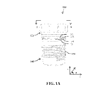
FIG. 1A shows a side elevation of one embodiment of a tamper-resistant closure
assembly having an elongate body coupled with a complementary ferrule.
FIG. 1B shows an exploded view of the tamper-resistant closure assembly shown
in FIG.
1A.
FIG. 2A shows a side elevation of an elongate body as shown in FIG. 1B.
FIG. 2B shows a perspective view from below the elongate body shown in FIGS.
1B and
2A.
FIG. 3 shows a longitudinal cross-section of the tamper-resistant closure
assembly taken
.. along section line A-A' in FIG. 1A.
FIG. 4A shows a portion of a cross-sectional view similar to the view in FIG.
3 as an
alternative arrangement of a tamper-resistant closure assembly as shown in
FIG. 1A.
FIG. 4B shows a portion of a cross-sectional view similar to the view in FIG.
3 revealing
another embodiment of the tamper-resistant closure assembly as shown in FIG.
1A.
FIG. 4C shows a portion of a cross-sectional view similar to the view in FIG.
3 revealing
yet another embodiment of the tamper-resistant closure assembly as shown in
FIG. 1A.
FIG. 4C' shows an embodiment of a resilient ring structure depicted in FIG.
4C.
FIG. 4C" shows another embodiment of the resilient ring structure depicted in
FIG. 4C.
11
CA 03030583 2019-01-07
WO 2018/200741 PCT/US2018/029461
FIG. 4D shows a portion of a cross-sectional view similar to the view in FIG.
3 revealing
an alternative embodiment of the tamper-resistant closure assembly as shown in
FIG. 1A.
FIG. 4E shows a portion of a cross-sectional view similar to the view in FIG.
3 revealing
yet another embodiment of the tamper-resistant closure assembly as shown in
FIG. 1A.
FIG. 5A shows an exploded view of a tamper-resistant container incorporating a
tamper-
resistant closure assembly as shown in FIGS. 1A, 4A, 4B, and 4C and a
complementarily
configured sheath.
FIG. 5B shows a side elevation view of the container shown in FIG. 5A in a
closed
arrangement.
FIG. 6A shows a perspective view from above the container depicted in FIG. 5B.
FIG. 6B shows a bottom plan view of the tamper-resistant closure assembly
shown in
FIGS. 1A, 1B and 3.
FIG. 6C shows a top plan view of the tamper-resistant closure assembly shown
in FIGS.
1A, 1B and 3.
FIG. 7A shows a longitudinal cross-section of the container depicted in FIG.
6A with a
cigarette securely retained by the tamper-resistant closure assembly.
FIG. 7B shows a longitudinal cross-section view of an inverted tamper-
resistant closure
assembly supporting a cigarette.
FIG. 7C shows a bottom plan view, a side elevation view, and an isometric view
of an
insert having a fluted aperture defining a plurality of resilient flaps for
retaining a variety of sizes
of a cigarette.
FIG. 8A shows a perspective view from above another embodiment of a tamper-
resistant
container.
FIG. 8B shows a front elevation view of the tamper-resistant container
depicted in FIG.
8A.
FIG. 8C shows a side elevation view of the tamper-resistant container depicted
in FIG.
8A.
FIG. 9 shows an exploded view of the tamper-resistant container depicted in
FIG. 8A.
FIG. 10A shows a longitudinal cross-section view of the tamper-resistant
container
depicted in FIG. 8A taken along line C-C'.
FIG. 10B shows an enlarged view of a portion of the vertical shaft and the
latch depicted
in FIG. 10A.
FIG. 11A shows a perspective view from above an externally threaded ember
remover.
FIG. 11B shows a top plan view of the ember remover depicted in FIG. 11A.
FIG. 11C shows a perspective view from below the ember remover depicted in
FIG. 11A.
12
CA 03030583 2019-01-07
WO 2018/200741 PCT/US2018/029461
FIG. 12 shows an embodiment of a circuit diagram of a lighter.
FIG. 13A shows a front elevation view of another tamper-resistant container.
FIG. 13B shows a perspective view from above the tamper-resistant container
depicted in
FIG. 13A. In FIG. 13B, the container is opened to reveal several storage
compartments.
FIG. 13C shows a rear elevation view of the tamper-resistant container
depicted in FIG.
13A. In FIG. 13C, the container is closed.
FIG. 14 shows an exploded view of the tamper-resistant container depicted in
FIG. 13A.
FIG. 15A shows a perspective view of another tamper-resistant closure kit
assembly.
FIG. 15B shows the tamper-resistant closure kit assembly depicted in FIG. 15A
where its
lid is open.
FIG. 15C shows the tamper-resistant closure kit assembly depicted in FIG. 15A
where
some components of the kit assembly are taken outside of the kit assembly.
DETAILED DESCRIPTION
The following describes various innovative principles related to tamper-
resistant closures
and enclosures. Aspects of disclosed subject matter pertain to tamper-
resistant containers and
closure assemblies for storing cigarettes. Therefore, with tamper-resistant
closures and containers
being but examples of disclosed subject matter used for illustrative purposes,
some disclosed
containers are configured to hold one cigarette. Other containers are
configured to receive one or
more such containers, and thereby to hold or store a plurality of cigarettes.
Still other
embodiments of disclosed containers can include components or accessories for
making, storing,
and/or facilitating consumption of cigarettes.
As noted, embodiments of tamper-resistant closures and containers described in
context
of storing cigarettes are, but particular examples of contemplated tamper-
resistant closures and
containers chosen as being convenient illustrative examples of disclosed
principles. One or more
of the disclosed principles can be incorporated in various other tamper-
resistant closures and
enclosures for storing other objects and/or materials, such as, for example,
medicine, medical
devices, nutrition supplements, food, tools, and so on. Accordingly, such
alternative
embodiments also fall within the scope of this disclosure.
I. TAMPER-RESISTANT CAP
FIGS. 1A and 1B show a tamper-resistant closure assembly, or cap 100. An
elongate
body 120 rests within an overlying, complementarily configured ferrule 160. As
shown in FIG.
1A, the body 120 is at rest in a longitudinally expanded position relative to
the ferrule 160.
Stated differently, the cap 100 is configured to bias, or urge, the elongate
body 120 and ferrule
13
CA 03030583 2019-01-07
WO 2018/200741 PCT/US2018/029461
160 longitudinally apart from each other within a selected, limited range of
motion along the x-
axis in FIG. 1A. The externally threaded ferrule 160 is generally free to
rotate circumferentially
of the elongate body 120 when in the expanded at-rest position shown in FIG.
1A. When the
elongate body 120 and the ferrule 160 are longitudinally urged together, and
the elongate body
120 and ferrule 160 are rotated relative to each other, the complementarily
arranged bosses 152,
154 positioned on the elongate body 120 and ferrule 160, respectively, urge
against each other to
prevent circumferential rotation of the elongate body 120 relative to the
ferrule 160. Thusly, the
elongate body 120 and ferrule 160 can be made to rotate together in unison
when a user presses
the elongate body 120 longitudinally and urges the elongate body 120 in
rotation. However,
absent longitudinal urging, the bosses, or teeth 152, 154 do not engage. Thus,
if the elongate
body 120 is urged in rotation without engaging the teeth 152, 154 with each
other, the elongate
body 120 will remain free to rotate relative to the ferrule 160, providing a
measure of resistance
to opening of a container into which the ferrule 160 is threadably received
(e.g., FIGS. 5B and
6A) by those lacking the skill or deftness to urge the elongate body 120
longitudinally of the
ferrule 160 to urge the teeth 152, 154 into engagement and simultaneously to
urge the cap 100 in
rotation (0-direction motion). The elongate body 120 and/or the ferrule 160
can be made of any
type of metal (e.g., aluminum), alloy, plastic, or other types of materials.
The Elongate Body
Referring to FIGS. 1A, 2A, and 2B, the elongate body 120 has a proximal end
122 and a
distal end 128. The proximal end 122 can have a recessed region 124 that can
be configured to
receive a complementarily sized insert 125. A top surface of the insert 125
can be decorated to
display logos, ornamentation, or other graphical and/or textual information.
An external major surface 123 of the elongate body 120 can define a
circumferentially
extending recess or groove 132 configured to receive a complementarily sized
seal member or
gasket 130. As shown in FIG. 1B, the seal member 130 can be arranged as an 0-
ring and can be
made of a suitable sealing material, such as, for example, a pliant rubber,
silicone, or other
polymer suitable for providing a water resistant and/or air-tight seal between
the external surface
123 of the elongate body 120 and an interior surface of a container (or sheath
200, FIG. 5A, 5B).
Referring now to FIG. 3, some embodiments of the elongate body 120 can define
a first
recessed region 172 and a second recessed region 176 joined together by a
transition region 174.
The transverse cross-section of each respective region (e.g., taken
transversely to the x-axis in
FIG. 1A, as in the r-0 plane) can have a circular or polygonal shape. Each
respective region can
be complementarily sized to matingly receive a correspondingly sized suction-
end of a cigarette
260, as illustrated by way of example in FIG. 7A. In a particular working
embodiment, the first
recessed region 172 has a transverse cross-sectional dimension D1 (FIG. 7B)
measured about 4.8
14
CA 03030583 2019-01-07
WO 2018/200741 PCT/US2018/029461
mm (e.g., between about 4.4 mm and about 5.2 mm, such as between about 4.7 mm
and about
4.9 mm) so as to matingly receive a "super-slim" cigarette. In the working
embodiment, the
second recessed region 176 has a transverse cross-sectional dimension D3
measuring about 7.9
mm (e.g., between about 7.3 mm and about 8.5 mm, such as between about 7.8 mm
and about
8.0 mm) so as to matingly receive a "king size" cigarette. The transition
region 174 can have
transverse cross-sectional dimension D2 measuring about 5.2 mm (e.g., between
about 4.9 mm
and about 5.5 mm, such as between about 5.1 mm and about 5.3 mm) so as to
receive a "standard
size" cigarette. As shown in FIG. 7A, the cap 100 can matingly receive a
suction end of a
cigarette 260 in the recess 172, 174, 176 to retain the cigarette 260. When a
sheath 200 overlies
.. that cap and cigarette assembly, the cigarette 260 can be suspended in the
sheath 200, as in FIG.
7A. By suspending or otherwise retaining the cigarette 260 within the sheath
260, a likelihood of
damage to the cigarette 260, as during shipping, storing, or transporting, can
be reduced.
Alternatively, when the cap 100 is removed from the sheath 200, the tamper-
resistant closure
assembly 100 can be inverted (see e.g., FIG. 7B) to be used as a cigarette
stand to stably and
.. securely hold a full or partially consumed cigarette between intermittent
uses and before the cap-
and-cigarette assembly is returned to the sheathed storage arrangement shown
in FIG. 7A.
In some embodiments, the interior surface 179 (or portion thereof) of any of
the regions
172, 174, 176 can have a grooved texture, and/or be coated with or made in
whole or part of a
plastic sheath, such as, for example, a molded polyurethane or rubbery pliant
material to provide
a secure frictional engagement and/or interference fit between the interior
surface 179 and a
cigarette received in the recess. FIG. 7C shows a bottom plan view, a side
elevation view, and an
isometric view of a sheath suitable to be inserted in or otherwise received by
a recessed region
172, 174, and/or 176 (FIG. 7B). The sheath insert has a fluted aperture 224
defining a plurality
of resilient flaps 223 for retaining a variety cigarette sizes. As a user
inserts a butt-end of a
cigarette in the fluted aperture 224, the resilient flaps deflect inwardly of
the body 221 of the
sheath 220. The flaps, being resilient, urge inwardly against the butt-end of
the cigarette, and
frictional engagement between the flaps and the cigarette body retains the
cigarette, generally as
shown in FIG. 7A. The illustrated sheath insert 220 has a shoulder 225 to urge
against the distal
end 128 of the elongate body 100. A distal face 222 of the insert 220 faces
outwardly of the
recessed region 172, 174, and/or 176. The body 221 of the sheath 220 can
matingly engage with
or be deposited on an inner major surface of the recess 172, 174, and/or 176.
In some sheath
embodiments, a grommet or other pliant member matingly engages a distal region
of the
elongate body 100 and defines a fluted or other aperture having one or more
resilient flaps 223.
The fluted or other aperture can receive a butt-end of a cigarette as
described above. The one or
CA 03030583 2019-01-07
WO 2018/200741 PCT/US2018/029461
more flaps 223 can be integrally formed as part of the elongate body 100 or
can be formed as a
portion of a separate member that matingly engages the elongate body.
In some embodiments, the interior surface 179 of any of the respective regions
172, 174,
176 can be longitudinally tapered to define a longitudinally decreasing cross-
section dimension
moving from the distal end 128 toward the proximal end 122 of the elongate
body 120. Such a
taper can enhance an interference fit or other mating engagement with a
cigarette received
therein. A degree of taper may vary among the different regions. For example,
in the embodiment
shown in FIG. 3, the transition region 174 has a higher degree of taper than
either of the first
recess region 172 and the second recess region 176. The longitudinal dimension
of each
respective region 172, 174, 176 can also be selected to accommodate different
lengths of a
cigarette's suction-end.
The Ferrule
Referring to FIG. 3, the ferrule 160 can define an interior major surface 162
and an
exterior major surface 164. The interior major surface 162 defines a generally
hollow tubular
structure that can include a proximal region 163 and a distal region 165. A
transverse cross-
section of the proximal region 163 and/or the distal region 165 can have a
circular or a polygonal
shape. In addition, the proximal region 163 and/or the distal region 165 can
be complementarily
sized and shaped to corresponds with an elongate body 120 received within the
ferrule 160, as
illustrated in FIGS. 3, 4A, 4B, and 4C, and described more fully below.
In some embodiments, the proximal region 163 can have a larger transverse
cross-
sectional dimension than a corresponding transverse cross-sectional dimension
of the distal
region 165. In the embodiment shown in FIG. 3, a sloped face 167 can be
positioned between the
proximal region 163 and the distal region 165 to provide a transition between
the regions.
Alternatively, the proximal region 163 may have the same or a comparably sized
transverse
cross-sectional dimension as the distal region 165.
Coupling Between the Elongate Body and the Ferrule
As noted above, the elongate body 120 can be slidably retained within the
ferrule 160 by
a shoulder 135 extending radially outward of the distal end 128 of the
elongate body 120. As
illustrated in FIG. 3, in some embodiments, the shoulder 135 can be positioned
at or adjacent the
.. distal end 128 of the elongate body 120. Accordingly, a longitudinally
facing face 134 of the
shoulder 135 can abut a distal end 166 of the ferrule 160 so as to retain the
elongate body 120
longitudinally within the ferrule 160 to limit an extent of longitudinal
separation between the
teeth 152, 154 positioned at the proximal end region.
Alternatively, the shoulder 135 can be positioned between the opposed ends
122, 128 of
the elongate body 120, as illustrated in FIG. 4C. In FIG. 4C, the interior
major surface 162c of
16
CA 03030583 2019-01-07
WO 2018/200741 PCT/US2018/029461
the ferrule 160c has a recessed region 161c sized and positioned in
correspondence with the
outwardly extending shoulder 135c of the elongate body 120c. Accordingly, the
shoulder 135c
can be received by and stably anchored within the proximal and distal extents
of the
corresponding recessed region 161c defined by the ferrule 160c after the
elongate body 120c and
the ferrule 160c are assembled (as by urging them together longitudinally).
Engagement Between the Elongate Body and the Ferrule
A resilient biasing member can resiliently urge the elongate body 120 and the
ferrule 160
longitudinally of each other to longitudinally separate the teeth 152, 154. As
described more
fully below, the biasing member and a complementary surface or other structure
arranged to urge
the body 120 and the ferrule 160 apart from each other can take many forms.
With such a biasing
member, when no external force is applied to the proximal end 122 of the
elongate body 120, the
elongate body 120 rests in a raised position relative to the ferrule 160 (see
e.g., FIG. 3). In such a
raised position, the teeth 152, 154 do not engage each other and rotation of
the elongate body
120 will not cause corresponding rotation of the ferrule 160 when the ferrule
160 is threadably
retained in a sheath 200. On the other hand, when a downward force is applied
to the proximal
end 122 of the elongate body 120, the elongate body 120 can move
longitudinally of the ferrule
160 to a lowered position. In such a lowered position, the teeth 152 of the
elongate body 120 can
urge against and rotationally engage the corresponding teeth 154 of the
ferrule 160. In that
arrangement, concurrent rotation of the elongate body 120 (clockwise or
counter-clockwise) can
urge the ferrule 160 in a corresponding rotation.
The teeth 152, 154 can have a variety of configurations. In some embodiments,
the
elongate body 120 can define a first plurality of juxtaposed teeth 152 spaced
apart from each
other to define a first plurality of juxtaposed recesses 153 therebetween. The
ferrule 160 can
further define a second plurality of juxtaposed teeth 154 spaced apart from
each other to define a
second plurality of juxtaposed recesses 155 therebetween. The first plurality
of juxtaposed teeth
152 can be complementary to the second plurality of juxtaposed recesses 155,
and the second
plurality of juxtaposed teeth 154 can be complementary to the first plurality
of juxtaposed
recesses 153. Thus, when the elongate body 120 moves to the lowered position
as by applying a
force to the proximal end 122, the first plurality of juxtaposed teeth 152 can
be respectively
received by the corresponding second plurality of recesses 155, and the second
plurality of
juxtaposed teeth 154 can be respectively received by the corresponding first
plurality of recesses
153. Accordingly, rotating the elongate body 120 can engage the ferrule 160,
causing the rotation
of the tamper-resistant closure assembly 100 relative to, for example, a
sheath 200.
Automatic Disengagement of the Elongate Body from the Ferrule
17
CA 03030583 2019-01-07
WO 2018/200741 PCT/US2018/029461
Under an internal force applied by the biasing member, when the force at the
proximal
end 122 is released, the elongate body 120 can automatically move
longitudinally upward to the
raised position shown in FIG. 3 so as to disengage its teeth 152 from the
teeth 154 of the ferrule
160. The first plurality of juxtaposed teeth 152 and the corresponding
recesses 153 can disengage
the complementary second plurality of juxtaposed recesses 155 and the
corresponding teeth 154.
As illustrated in FIG. 3, the tamper-resistant closure assembly 100 can
include a boss 140
positioned adjacent the distal end 128 of the elongate body 120. The boss 140
is configured to
urge resiliently outwardly against the interior major surface 162 of the
ferrule 160. As FIG. 3
shows, the ferrule 160 can define a region 167 so complementarily arranged
relative to the boss
140 as to resiliently urge the elongate body 120 in a proximal direction
relative to the ferrule 160
in correspondence with a radially outward force applied by the boss 140
against the interior
major surface 162. Alternatively, as shown in FIGS. 4D-4E and described more
fully below, the
ferrule can also define a resilient biasing member that is complementarily
arranged relative to a
structural element of the elongate body so as to resiliently urge the elongate
body in a proximal
direction relative to the ferrule in correspondence with a radially inward
force applied by the
resilient biasing member against the elongate body.
For example, FIG. 3 shows an embodiment where the boss 140 is positioned
adjacent a
distal end of a cantilevered spring lever, or cantilever 150. The proximal end
156 of the
cantilever 150 has a unitary construction with the elongate body 120, and a
body of the
cantilever 150 between the proximal end 156 and a free distal end 157 is
spaced from the wall
126 of the elongate body 120 as to define a distally extending arm 158 free to
deflect in a radial
direction relative to the wall 126 of the elongate body 120 and the ferrule
160. As the region 167
urges against the boss 140 to deflect the free distal end 157 of the
cantilever radially inward, a
restorative outward force is applied by the boss 140 to the region 167. When a
user releases a
longitudinal force from the proximal end 122, the slope of the region 167 can
urge the boss 140,
and thus the elongate body 120, longitudinally under the radially outward
restorative force
arising from a radially inward deflection of the cantilever 150. The
cantilever 150 can be made
of any types of spring resilient material so that the cantilever 150 urges
toward a biased position
(e.g., a radially inward position) by applying an external force and the
cantilever 150 resiliently
urges toward an unbiased position when the external force is removed.
In some embodiments, one or more spring levers 150 can be distributed
circumferentially
around the elongate body 120. For example, FIG. 6B shows three spring levers
150 uniformly
distributed around the elongate body 120. The number of spring levers 150 can
vary from three,
and the spring levers can be distributed asymmetrically and/or non-uniformly.
As illustrated in
FIG. 3, when the elongate body 120 is in the raised position relative to the
ferrule 160, the boss
18
CA 03030583 2019-01-07
WO 2018/200741 PCT/US2018/029461
140 can rest against the sloped face 167 positioned between the proximal
region 163 and the
distal region 165. The boss 140 can be moved toward the distal region 165 as
it slides along the
sloped face 167, as when the elongate body 120 moves toward the lowered
position under an
external force as the boss 140 moves distally, the free distal end 157 of the
cantilever 150 is
pushed radially inward. An interface force between the sloped face 167 and the
boss 140 has
both radial and longitudinal vector components. Thus, as the boss 140 on the
spring lever 150
urges radially outward under a resilient restorative force, the elongate body
120 is urged toward
the proximal region 163 and into the raised position when the external force
on the proximal end
122 is released.
Alternative Embodiments of the Boss and Related Structure
The following describes several alternative, but non-limiting, embodiments of
the
structure configured to resiliently engage and disengage the elongate body 120
and the ferrule
160.
Referring to FIG. 4A, an inner major surface 162a of a ferrule 160a can define
a recessed
area 168a positioned between the proximal region 163a and the distal region
165a. Proximally of
the recessed area 168a, the proximal region 163a can have a larger, a smaller,
or a similar
transverse cross-sectional dimension and/or shape compared to a transverse
cross-section of the
distal region 165a. A sloped face 167a can define a transition zone between
the recessed area
168a and for example the distal region 165a. When the elongate body 120a is in
the raised
position relative to the ferrule 160a, the boss 140a can rest against the
sloped face 167a. As with
the arrangement in FIG. 3, the boss 140a can be urged toward the distal region
165a under an
external force applied to the proximal end. As the boss 140a moves distally,
the sloped face 167a
urges the boss 140a inward radially. When the external force is released, the
boss 140a can move
radially outwardly and urge the elongate body 120a to the raised position
under a resilient,
restorative force arising from a deflection of the material surround the boss
140a.
Referring to FIG. 4B, another embodiment is shown and described. In this
example, an
inner major surface 162b of another ferrule 160b defines an inwardly
protruding shoulder 169b
positioned between the proximal region 163b and the distal region 165b.
Proximally of the
inwardly protruding shoulder 169b, the proximal region 163b can have a larger,
a smaller, or a
similar transverse cross-sectional dimension and/or shape compared to the
cross-section of the
distal region 165b. The shoulder 169b can define a curved or rounded face
169b' defining an
interface between the inwardly protruding shoulder 169b and the boss 140b.
When the elongate
body 120b is in the raised position relative to the ferrule 160b, the boss
140b can rest atop the
inwardly protruding shoulder 169b. The boss 140b can be urged toward the
distal region 165b as
it slides across the face 169b' under downward external force, as can be
applied to the proximal
19
CA 03030583 2019-01-07
WO 2018/200741
PCT/US2018/029461
end. The boss 140b can expand radially outwardly and move back toward the
proximal region
163b under a restorative, resilient force arising from material deflections.
Such radial movement
of the boss 140b can urge the elongate body 120b toward the raised position
when the external
force on the proximal end is released.
FIG. 4C shows yet another embodiment. In this example, a resilient ring
structure 140c
can apply a resilient, restorative force to the elongate body 120c. For
example, the resilient ring
structure 140c can be a C-ring 140c', as illustrated in FIG. 4C', which can be
made of a
resiliently deformable material. In another example, the resilient ring
structure 140c can be a
spiral ring 140c", as illustrated in FIG. 4C", which can be resiliently
compressed. The resilient
ring structure 140c can be positioned distally of the distal end 128c of the
elongate body 120c
within the ferrule 160c. In some instances, the resilient ring structure 140c
can form part of the
elongate body 120c or ferrule 160c, and in other instances, the resilient ring
structure 140c can
be a separate component. As illustrated in FIG. 4C, a sloped face 167c can be
positioned between
the proximal region 163c and the distal region 165c. When the elongate body
120c is in the
raised position relative to the ferrule 160c, the resilient ring structure
140c can rest against the
sloped face 167c.The resilient ring structure 140c can be urged toward the
distal region 165c. As
it slides down the sloped face 167c, the resilient ring structure 140c
compresses radially, as under
an external force applied to the proximal end of the elongate body 120c. Under
the resilient,
restorative force arising from compression of the resilient ring structure
140c, the resilient ring
structure 140c can expand radially outward when the external force is
released. Such radial
expansion along the sloped face 167c urges the resilient ring structure 140c
proximally. As the
elongate body 120c rests against the resilient ring structure 140c, proximal
movement of the
resilient ring structure 140c tends to urge the elongate body 120c proximally
of the ferrule 160c.
Referring to FIG. 4D, an inner major surface 162d of a ferrule 160d can define
a
cantilevered arm 169d positioned between the proximal region 163d and the
distal region 165d.
The cantilevered arm 169d can have a proximal end 168d affixed to the inner
major surface 162d
of the ferrule 160d and a free distal end 167d spaced from the inner major
surface 162d. The
cantilevered arm 169d can be made of resilient spring material. Proximally of
the cantilevered
arm 169d, the proximal region 163d can have a larger, a smaller, or a similar
transverse cross-
sectional dimension and/or shape compared to a transverse cross-section of the
distal region
165d. A sloped face 140d (or alternatively a protruding shoulder 140b as shown
in FIG. 4B) can
define an interface with the cantilevered arm 169d. When the elongate body
120d is in the raised
position relative to the ferrule 160d, the sloped face 140d can rest against
the cantilevered arm
169d adjacent its proximal end 168d. The sloped face 140d can be urged toward
the free distal
end 167d of the cantilevered arm 169d under an external force applied to the
proximal end of the
CA 03030583 2019-01-07
WO 2018/200741 PCT/US2018/029461
elongate body 120d. As the sloped face 140d moves distally, the sloped face
140d urges the
cantilevered arm 169d outward radially. When the external force is released,
the cantilevered arm
169d can move radially inwardly under a resilient, restorative force arising
from a deflection of
the cantilevered arm 169d, thus urging the sloped face 140d toward the
proximal end 168d, and
urging the elongate body 120d to the raised position.
Referring to FIG. 4E, an inner major surface 162e of a ferrule 160e can define
a
deformable protrusion 169e positioned between the proximal region 163e and the
distal region
165e. The deformable protrusion 169e can have a proximal end 168e and a distal
end 167e, each
end being affixed to the inner major surface 162e of the ferrule 160e. The
deformable protrusion
169e can be made of resilient spring material. Proximally of the deformable
protrusion 169e, the
proximal region 163e can have a larger, a smaller, or a similar transverse
cross-sectional
dimension and/or shape compared to a transverse cross-section of the distal
region 165e. An
outwardly extending shoulder 140e (or alternatively a sloped face 140d as
shown in FIG. 4D)
can define an interface with the deformable protrusion 169e. When the elongate
body 120e is in
the raised position relative to the ferrule 160e, the shoulder 140e can rest
atop the deformable
protrusion 169e adjacent its proximal end 168e. The shoulder 140e can be urged
toward the
distal end 167e of the deformable protrusion 169e under an external force
applied to the
proximal end of the elongate body 120e. As the shoulder 140e moves distally,
the shoulder 140e
urges the deformable protrusion 169e outward radially. When the external force
is released, the
deformable protrusion 169e can move radially inwardly under a resilient,
restorative force
arising from a deflection of the deformable protrusion 169e, thus urging the
shoulder 140e
toward the proximal end 168e, and urging the elongate body 120e to the raised
position.
Sheaths
In some embodiments, the tamper-resistant closure assembly 100 can also
include an
external engagement member 170 configured to matingly engage a sheath 200, or
other
containment body, or enclosure. In some embodiments, the external engagement
member 170
can be disposed on or extend from the exterior major surface 164 of the
ferrule 160. The external
engagement member 170 can be configured to removably couple with a
complementarily
arranged region 210 of the sheath 200. In some embodiments, the external
engagement member
170 can include an external thread 170a and the complementarily arranged
region 210 of the
sheath 200 can include an internal thread 210a that is complementary to the
external thread 170a
to allow the cap 100 to threadably engage with the sheath 200. Thus, the
tamper-resistant closure
assembly 100 threadably engages with the sheath 200 to form a closed, tamper-
resistant
container 250 (FIG. 5B).
21
CA 03030583 2019-01-07
WO 2018/200741 PCT/US2018/029461
With embodiments described above, the elongate body 120 can rotationally
engage the
ferrule 160 when the elongate body 120 is pressed to a lowered position. In
addition, when force
is relieved from the proximal end 122 of the elongate body 120, the elongate
body 120 can
automatically urge upward and disengage from the ferrule 160. Thus, to close
or open the
container 250, a user generally must press the elongate body 120 downward and
rotate it
clockwise or counterclockwise to rotationally engage the elongate body 120
with the ferrule 160
and to threadably engage or disengage the cap 100 with or from the sheath 200.
When the
downward force is removed, the elongate body 120 can disengage from the
ferrule 160, so that
rotating the elongate body 120 will not cause corresponding rotation of the
ferrule 160, thus
disabling a threadable rotation of the ferrule 160 relative to the sheath 200,
and thus of the
tamper-resistant closure assembly 100 within the sheath 200. Accordingly, the
tamper-resistant
closure assembly 100 may prevent inadvertent opening of the container 250 by
those lacking the
skill and/or dexterity to simultaneously urge the elongate body 120
longitudinally and
circumferentially.
Referring FIG. 7A, a longitudinal dimension of the sheath 200 can be slightly
longer than
the greatest anticipated length of an intended cigarette (e.g., a super slim
sized cigarette). Thus,
when a cigarette 260 is stored in the container 250, a suction-end of the
cigarette 260 can be
securely received in any of the recess regions 172, 174, 176 of the elongate
body 120, and the
other end 262 of the cigarette 260 can be prevented from touching the distal
end 252 of the
sheath 200. The transverse cross-section dimension of the sheath 200 can be
slightly larger than a
circumferential dimension of the cigarette 260 so that the cigarette 260 does
not touch an inner
major surface of the sheath 200. Accordingly, the cigarette 260 can be
securely stored inside the
container 250, without getting damaged by touching the bottom or inner surface
of the container
250 even during abrupt movement or when the container 250 is dropped from a
selected height
to the ground.
As described above, the tamper-resistant closure assembly 100 can include a
seal member
130. When the external engagement member 170 is coupled with the
complementarily arranged
region 210 of the sheath 200, the seal member 130 can extend from an external
surface 123 of
the elongate body 120 to a corresponding internal surface of the sheath 200 to
sealingly engage
the sheath 200. Accordingly, the container 250 can be in some instances, air
and/or water
resistant, hermetically sealed, and in other instances so as to maintain
freshness of the
herbaceous cigarette stored therein, e.g., by protecting it from the sunlight
and changes in
humidity. In addition, the seal member 130 may be color coded so that it
allows a user to
recognize and classify different types of cigarettes without the need to take
it out of the container
250.
22
CA 03030583 2019-01-07
WO 2018/200741 PCT/US2018/029461
OTHER TAMPER-RESISTANT CONTAINERS
FIGS. 8A through 13 show alternative embodiments of tamper-resistant
containers. Some
of the containers may contain one or more tamper-resistant containers 250
described above for
storing cigarettes, and may also incorporate one or more other smokers'
accessories, such as, for
example, a cleaner, a lighter, a grinder, a storage container for herbaceous
material, package of
rolling papers, etc., so that a user may carry necessary or desirable elements
in one discreet and
convenient package.
Latched Tamper-Resistant Container
FIGS. 8A-8C show different views of a tamper-resistant container 300 and FIGS.
9, 10A
and 10B show aspects of several associated structural components.
The tamper-resistant container 300 can include a cap 320, an interior frame or
chassis
350, and a body cover, or case 330 defining an interior compartment 310 that
slidably receives
the interior frame 350. The body cover 330 can be complementarily arranged
relative to the cap
320 to enclose the compartment 310 when the cap 320 covers a top opening of
the compartment
310. In some embodiments, an upper region of the cap 320 can define a recessed
region 324
configured to receive a complementarily sized insert 325. The insert can be
decorative and/or
convey information, such as ornamentation, branding, content, or type of
cigarette, etc. For
example, a top surface of the insert 325 can display logos or other graphical
and/or textual
information.
The interior frame 350 can have an upper plate 351 defining a plurality of
apertures 354a,
each configured to slidably receive a container 250. In some embodiments, a
receptacle 354 can
be positioned in correspondence with each aperture 354a. In some embodiments,
each receptacle
354 can be complementarily sized and shaped to slidably receive a tamper-
resistant container
250 described above. In some embodiments, one receptacle 354 may also be
configured to
removably receive a cleaner 332 as described more fully below. In certain
embodiments, the
interior frame 350 may also contain corresponding receptacles 358 and 359 to
respectively
receive a vertical shaft 380 and a cigarette lighter 390 or another component
or accessory, as
described in more detail below.
In some embodiments, the container 300 can include a latch 340 and a switch
360. As
described more fully below, the switch 360 can be operatively coupled to the
lighter 390 to
control its operation. The latch 340 can be operated to open and/or close or
to retain and release
the cap 320 so as to expose or to cover the compartment 310. In addition, the
latch 340 and/or
the cap 320 can also be operatively coupled to the lighter 390 so as to
implement a safety
mechanism for the operation of the lighter 390. The latch 340 and the switch
360 may be
23
CA 03030583 2019-01-07
WO 2018/200741 PCT/US2018/029461
positioned at opposite sides of the closure assembly 300 as illustrated in
FIGS. 8-10, or they may
be positioned in another selected region of the body cover 330.
In certain embodiments, the tamper-resistant container 300 can also include a
seal
member 326 positioned underneath or as part of the cap 320 and over the upper
plate 351 of the
interior frame 250. The seal member 326 can be made of any known or to be
discovered sealing
materials, such as rubber, silicone, etc., to provide air-tight and water-
resistant properties of the
container 300 when the cap 320 is closed.
Each of the above described components, e.g., the cap 320, the body cover 330,
the
interior frame 350, the latch 340, the switch 360, the shaft 380, etc., can be
made of any suitable
material, e.g., aluminum, alloy, plastic, or other types of materials.
Latch Mechanism: Vertical Shaft
Referring to FIGS. 10A and 10B, the cap 320 can be affixed to a proximal end
381 of a
vertical shaft 380, so as to be cantilevered from the vertical shaft 380 when
the cap 320 is
opened.
In some embodiments, the shaft 380 can define a first keymate 341 and a second
keymate
343. In some embodiments, each keymate 341, 343 is formed by a recessed region
on the shaft
380. The first keymate 341 can be positioned longitudinally proximal of the
second keymate 343
relative to the cap 320, vertical longitudinal distance between the first
keymate 341 and the
second keymate 343 can be predefined, e.g., in a range between about 1/4 inch
to about 1 inch,
such as between about 1/2 inch and about 3/4 inch, in correspondence with a
desired spacing
between the cap 320 and the body cover 330 when the cap 320 is opened. The
first keymate 341
and second keymate 343 can be circumferentially offset from each other, as
well. The
circumferential offset can range between about 20 degrees and about 340
degrees, such as
between about 90 degrees and about 270 degrees, with a particular offset being
about 180
degrees. Although not shown in the figures, the shaft 380 may contain more
than two keymates,
and each of the keymates can be longitudinally separated from the others and
be
circumferentially offset from each of the other keymates.
The shaft 380 can have an outwardly extending shoulder forming an upper stop
344
positioned longitudinally proximal of the first keymate 341, and an outwardly
extending
shoulder forming a lower stop 346 positioned longitudinally distal of the
second keymate 343.
When the shaft 380 is slid proximally along its longitudinal axis, upward
movement can be
limited by the upper stop 344 engaging or contacting an upper barrier 345 of
the interior frame
350. Similarly, when the shaft 380 is longitudinally translated downward
(distally), downward
movement can be limited by the lower stop 346 engaging or contacting a lower
barrier 347 of the
interior frame 350.
24
CA 03030583 2019-01-07
WO 2018/200741 PCT/US2018/029461
In certain embodiments, a biased element, e.g., a coil, spring, etc. (not
shown) may be
positioned circumferentially around a distal end 382 of the shaft 380 to urge
against the lower
stop 346 so as to urge the shaft 380 upward (proximally). In certain
embodiments, a torsion
spring (not shown) may be placed around the shaft 380 so as to urge the shaft
in rotation about
its longitudinal axis.
Latch Mechanism: Latch Arm
Still referring to FIGS. 10A and 10B, the latch 340 can include a key, or
latch arm 342
that is complementarily sized and shaped to selectively and matingly engage
the first keymate
341 and the second keymate 343. The latch 340 is configured to be movable
between a locked
position and a released position. The latch 340 is in the locked position when
the key 342
matingly engages the first keymate 341 or the second keymate 343, and the
latch 340 is in the
released position when the key 342 disengages the first keymate 341 or the
second keymate 343.
Thus, the cap 320 can be locked closed or locked open.
For example, to disengage the key 342 from the respective keymate 341 or 343,
the latch
340 can be pushed inwardly relative to an outer major surface of the case 330
so that the key 342
moves away from the shaft 380 and the respective keymate. Accordingly, the
shaft 380 becomes
unlocked from the key 342, allowing the shaft to freely translate along its
longitudinal axis and
rotate around the longitudinal axis. By translating vertically and/or rotating
angularly the shaft
380, each keymate 341, 343 can be selectively positioned to receive the key
342. Release of the
latch 340 can cause the key 342 to move, e.g., laterally outward, to matingly
engage the
respective keymate 341, 343. Accordingly, the shaft 380 becomes locked by the
key 342 so that
its longitudinal translation and rotational movement are restricted until the
key 342 is removed
from the respective keymate 341, 343.
As illustrated in FIGS. 10A and 10B, the shaft 380 can be secured in a closed
position
with the affixed cap 320 covering the top opening of the compartment 310 when
the latch 340 is
in the locked position and the key 342 matingly engages the first keymate 341.
Stated differently,
the longitudinal position and angular orientation of the first keymate 341 can
be so configured
that when it matingly engages the key 342, the affixed cap 320 is positioned
immediately atop
the case 330 to cover the compartment 310. Further, the shaft 380 can also be
secured in a
deployment position (not shown) where the affixed cap 320 is displaced from
the top opening of
the compartment 310. For example, the latch 340 can be in the locked position
and the key 342
can matingly engage the second keymate 343 to retain the cap 320 in an open
position. Stated
differently, the longitudinal position and angular orientation of the second
keymate 342 can be so
configured that when the key 342 matingly engages the keymate 342, the affixed
cap 320 is
positioned to expose the compartment 310. For example, the affixed cap 320 can
be raised to a
CA 03030583 2019-01-07
WO 2018/200741
PCT/US2018/029461
deployment height above the top opening of the compartment and rotated to a
deployment angle.
The deployment height is about the vertical distance between the first keymate
341 and the
second keymate 343, and the deployment angle is about the circumferential
offset between the
first keymate 341 and the second keymate 343.
In certain embodiments, when the key 342 matingly engages the first keymate
341, the
lower stop 346 urges against the lower barrier 347, and when the key 342
matingly engages the
second keymate 342, the upper stop 344 urges against the upper barrier 345.
Thus, the lower and
upper stops 346, 344 and the corresponding lower and upper barriers 347, 345
can be used to
restrict a longitudinal extend of translation of the shaft 380 and to
facilitate locating the first and
second keymates 341, 342, respectively.
Cleaners
In some embodiments, a cleaner, or ember remover 332 can have a sheath 333
that has a
substantially similar cross-sectional shape and dimension compared to the
sheath 200 of the
tamper-resistant container 250 described above. Thus, the sheath 333 of the
cleaner may be
interchangeably repositioned among the several apertures 354a. A receptacle
354 of the interior
frame 350 can slidably retain either a tamper-resistant container 250 or a
cleaner 332.
In certain embodiments, the cleaner 332 can have a shaft assembly 370.
Generally, the
shaft assembly 370 can have an external structure similar to an external major
surface of the
tamper-resistant closure assembly 100 described above. For example, as
illustrated in FIGS.
11A-11C, the shaft assembly 370 can have an external thread 372 configured to
removably
engage an internal thread of the sheath 333.
An internal major surface 371 of the shaft assembly 370 can define an open
recess 379.
In certain embodiments, a floor 375 of the recess 379 can include a conically
recessed region 377
and a plurality of slots 374 extending through the floor 375, thereby defining
a plurality of
exposed edges 376. In some embodiments, the floor 375 of the recess 379 can
include a heat-
resistant material, e.g. zinc alloy.
A user may rub smoldering end of a cigarette against the exposed edges 376 on
the floor
375 to remove ashes or an ember therefrom. Debris from the cigarette can fall
through the slots
374 and into the sheath 333. Thus, the shaft assembly 370 can be used as a
cleaning device to
remove the ashes of the cigarette before storing a partially consumed
cigarette in one of the
tamper-resistant containers 250, and the sheath 333 can be used for collecting
the cigarette ash
and other debris. Similar to the tamper-resistant container 250 described
above, the proximal end
of the cleaner 332 can sealing engage a seal to inhibit the odor from escaping
the cleaner 332
and/or the container 300.
Lighter
26
CA 03030583 2019-01-07
WO 2018/200741 PCT/US2018/029461
A lighter 390 can include a heating element 391 and an electronic circuitry
393 (see e.g.,
FIG. 12) that is configured to activate or deactivate the heating element 391.
Activation of the
heating element 391 can cause an electrical current to pass through and
resistive heating can
increase its surface temperature sufficiently to ignite a cigarette. The
lighter 390 can include a
battery 392 to power the electric circuitry. In some embodiments, the battery
392 can be
rechargeable, and the lighter 390 can have an interface 394 that can be used
to connect the
rechargeable battery 392 to an external charger. One exemplary, but non-
limiting example of
such an interface 394 can be a USB port.
In some embodiments, the operation of the electronic circuitry 393 can be
controlled by
the switch 360, which can be turned ON or OFF. For example, the electronic
circuitry 393 can
deactivate the heating element 391 when the switch 360 is turned OFF (e.g.,
the circuit is
opened), and the electronic circuitry 393 cannot activate the heating element
391 unless the
switch 360 is turned ON (e.g., the circuit is closed). In some embodiments,
the electronic
circuitry 393 can be further coupled to another controlling element, which can
function as a
safety mechanism to prevent accidentally turning ON the switch (e.g., closing
the circuit) and
activating the heating element 391. For example, the controlling element can
be the latch 340,
and the electronic circuitry 393 can be configured to activate the heating
element 391 only when
the latch 340 is in the released position and the switch 360 is turned ON, and
deactivate the
heating element 391 when the latch 340 is in the locked position or the switch
360 is turned OFF.
In another example, the controlling element can be the shaft 380, and the
electronic circuitry 393
can be configured to activate the heating element 391 only when the shaft 380
is in the
deployment position and the switch 360 is turned ON, and deactivate the
heating element 391
when the shaft 380 is in the closed position or the switch 360 is turned OFF.
Alternatively, the
controlling element can be the cap 320, and the electronic circuitry 393 can
be configured to
activate the heating element 391 only when the cap 320 is open (i.e., the
compartment 310 is
exposed) and the switch 360 is turned ON, and deactivate the heating element
391 when the cap
320 is closed (i.e., the compartment 310 is covered) or the switch 360 is
turned OFF. For
example, contact between the upper stop 344 can close a portion of the
circuitry so when the
switch 360 is turned ON, current flows to the heating element 391.
Alternatively, the lower stop
346 can activate, e.g., a relay to open the circuitry, such that even if the
switch 360 is turned ON,
electrical flow through the heating element 391 is inhibited or altogether
prevented when the cap
320 is closed. In addition, the electronic circuitry 393 may be coupled to an
indicator (not
shown) so as to provide a user perceivable signal (e.g., LED light, beep
sound, etc.) that
indicates the status of the electronic circuit (e.g., activated or
deactivated) and/or the temperature
of the heating element 391.
27
CA 03030583 2019-01-07
WO 2018/200741 PCT/US2018/029461
Alternative Tamper-Resistant Container
FIGS. 13A-13C show different views of another embodiment of a tamper-resistant
container 400 and FIG. 14 shows several structural components.
As shown, the container 400 can include a hinged cap 420, an interior frame
450, and a
.. body cover, or case 430 defining an interior compartment 410 that slidably
receive the interior
frame 450. The case 430 can be complementarily arranged relative to the cap
420 to enclose the
compartment 410 when the cap 420 covers a top opening of the compartment 410.
The cap 420
can be hingedly connected to the case 430 via a hinge 460. The cap 420 can be
coupled to an
opener 440 (e.g., a button, a clip, a mechanical or electrical switch, etc.).
Activation of the
opener 440 is configured to open the cap 420 and expose the compartment 410.
The hinge 460
and the opener 440 may be positioned at opposite sides of the container 400,
or they may be
positioned in another selected region of the case 430.
The interior frame 450 can have an upper plate 451 defining a plurality of
apertures 454a,
each configured to slidably receive a container 250. In some embodiments, a
receptacle 454 can
be positioned in correspondence with each aperture 454a. In some embodiments,
each receptacle
454 can be complementarily sized and shaped to slidably receive a tamper-
resistant container
250 described above. In some embodiments, one receptacle 454 may also be
configured to
removably receive a cleaner 432 as described above. In certain embodiments,
the interior frame
450 may also be configured to receive a cigarette lighter 490 or another
component or accessory
as described above.
In some embodiments, the container 400 can include a switch 495, which can be
operatively coupled to the lighter 490 to control its operation. For example,
the lighter 490 can
be deactivated when the switch 495 is turned OFF, and the lighter 490 cannot
be activated unless
the switch 495 is turned ON. The opener 440 and/or the cap 420 can also be
operatively coupled
to the lighter 490 so as to implement a safety mechanism for the operation of
the lighter 490. For
example, the lighter 490 can be configured to be activated only when the cap
420 is open and the
switch 495 is turned ON, and be deactivated when the cap 420 is closed or the
switch 495 is
turned OFF.
In certain embodiments, the container 400 can also include a seal member 426
positioned
underneath or as part of the cap 420 and over the upper plate 451 of the
interior frame 450. The
seal member 426 can be made of any sealing materials, such as rubber,
silicone, etc., to provide
air-tight and water-resistant properties of the container 400 when the cap 420
is closed.
Each of the above described components, e.g., the cap 420, the case 430, the
interior
frame 450, the opener 440, the switch 495, etc., can be made of any suitable
material, e.g.,
aluminum, alloy, plastic, or other types of materials.
28
CA 03030583 2019-01-07
WO 2018/200741 PCT/US2018/029461
KIT ASSEMBLY
FIG. 15A-C show a tamper-resistant, waterproof, and airtight kit assembly 500,
which
can contain a plurality of necessary elements to manually assemble a tobacco
and some related
accessories. For example, the kit assembly 500 can include a hermetically
sealed box 505 for the
storage of tobacco or other cigarette fill materials, keeping them fresh and
safe from elements
like air and light. For example, the box 505 may be made of stainless steel
and have a
polycarbonate odor proof airtight lid. Other materials can also be used.
The kit assembly 500 can have a tamper-resistant opener 510. In some
embodiments, the
tamper-resistant opener 510 can include a fingerprint recognition system that
allows only
authorized user who has the matching fingerprint to access the contents stored
inside the kit
assembly 500. Other techniques can also be incorporated in the tamper-
resistant opener 510, e.g.,
the voice authentication system, the iris recognition system, the password
protected keypad, etc.
An indicator 512 may provide a user perceivable feedback (e.g., LED display,
sound, etc.) on the
status of the kit assembly 500 (e.g., battery power, temperature, humidity,
lid open or close, etc.).
In addition, a key and a lock (not shown) may also be provided for
mechanically opening the kit
assembly 500 if necessary.
Some representative, but non-limiting components contained in the kit assembly
500 can
include: a grinder 526, a humidor 524, a pack of rolling papers 520 of varying
sizes (e.g., super
slim, standard, king, etc.), a smoking tip 532, a set of wood matches, a USB
lighter 528, one or
more tamper-resistant containers 530, a battery (not shown), etc. The humidor
524 may be made
of a metallic or plastic box with a plastic or metallic cover 524a for the
storage of tobacco or
other cigarette fill materials. The humidor 524 may have sensors that measure
the temperature
and humidity inside the box and may also contain a control circuit and
associated actuators to
adjust the temperature and humidity.
VI. OTHER EMBODIMENTS
It should be understood that the various types of assemblies described above
represent
only exemplary embodiments of the inventive subject matter. Other embodiments
can be
implemented based on the same general principles described herein.
Directions and other relative references, e.g., up, down, left, right, etc.,
may be used to
facilitate discussion of the drawings and principles herein, but are not
intended to be limiting.
For example, certain terms may be used such as "upper," "lower," "horizontal,"
"vertical," "top",
"bottom," and the like. Such terms are used, where applicable, to provide some
clarity of
description when dealing with relative relationships, particularly with
respect to the illustrated
embodiments. Such terms are not, however, intended to imply absolute
relationships, positions,
29
CA 03030583 2019-01-07
WO 2018/200741 PCT/US2018/029461
and/or orientations. As used herein, "and/or" means "and" or or, as well as
"and" and "or."
Moreover, all patent and non-patent literature cited herein is hereby
incorporated by reference in
its entirety for all purposes.
The principles described above in connection with any particular example can
be
combined with the principles described in connection with another example
described herein.
Accordingly, this detailed description shall not be construed in a limiting
sense, and following a
review of this disclosure, those of ordinary skill in the art will appreciate
the wide variety of
tamper-resistant closure devices can be devised using the various concepts
described herein.
Moreover, those of ordinary skill in the art will appreciate that the
exemplary
embodiments disclosed herein can be adapted to various configurations and/or
uses without
departing from the disclosed principles. Applying the principles disclosed
herein, it is possible to
provide a wide variety of tamper-resistant closure assemblies adapted to store
articles other than
the cigarettes.
The previous description of the disclosed embodiments is provided to enable
any person
skilled in the art to make or use the disclosed innovations. Various
modifications to those
embodiments will be readily apparent to those skilled in the art, and the
generic principles
defined herein may be applied to other embodiments without departing from the
spirit or scope
of this disclosure. Thus, the claimed inventions are not intended to be
limited to the
embodiments shown herein, but are to be accorded the full scope consistent
with the language of
the claims, wherein reference to an element in the singular, such as by use of
the article "a" or
an is not intended to mean one and only one unless specifically so stated, but
rather one or
more. All structural and functional equivalents to the features and method
acts of the various
embodiments described throughout the disclosure that are known or later come
to be known to
those of ordinary skill in the art are intended to be encompassed by the
features described and
claimed herein. Moreover, nothing disclosed herein is intended to be dedicated
to the public
regardless of whether such disclosure is explicitly recited in the claims. No
claim element is to
be construed under the provisions of 35 USC 112, sixth paragraph, unless the
element is
expressly recited using the phrase "means for or "step for.
Thus, in view of the many possible embodiments to which the disclosed
principles can be
applied, we reserve to the right to claim any and all combinations of features
and technologies
described herein as understood by a person of ordinary skill in the art,
including, for example, all
that comes within the scope and spirit of the following claims.