Note : Les descriptions sont présentées dans la langue officielle dans laquelle elles ont été soumises.
CA 03030761 2019-01-11
WO 2018/013812 1
PCT/US2017/041934
PATIENT MONITORING SYSTEM
REFERENCE TO RELATED APPLICATION
The present application claims the benefit of United States Provisional
Patent Application No. 62/361,548, filed July 13, 2016, which is hereby
incorporated by reference.
BACKGROUND
The risk of a patient falling from a bed, chair, or other supporting structure
is an important concern for those responsible for providing patient care.
While
patient falls are not always serious, the possibility of additional injuries
to the
patient, and the potential liabilities for caregivers makes avoiding patient
falls an
important concern.
Patients who fall may experience considerable pain and discomfort and
may require additional time to heal old injuries that have been aggravated by
the
fall, or new injuries caused by the event itself. For healthcare providers,
patient
falls generally mean additional costs, some or all of which the facility may
be
forced to write-off. For insurance companies, the additional risk of injury
from
patient falls increases costs making it generally more expensive to provide
health
coverage to patients and liability insurance for hospitals and caregivers.
Also, the need to prevent patient falls is generally increasing as the
population ages. Age increases both the overall risk of falling and the
likelihood of
injury from a fall. Elderly people may be especially at risk of repeat falls
which
may increase the time required to heal, and result in serious or life-
threatening age-
related complications.
Healthcare regulations may also impact the cost of patient falls. Some
government agencies may withhold funds, refuse licenses or permits, or
otherwise
penalize providers with higher numbers of patient falls. On the other hand,
increased funding may be available to providers who reduce or eliminate
incidents
involving fall-related injuries.
CA 03030761 2019-01-11
WO 2018/013812 2
PCT/US2017/041934
Thus patients, caregivers, and medical institutions would benefit from
predicting when a patient is about to fall and preventing it from happening
rather
than treating patients from the injuries they may sustain as a result.
CA 03030761 2019-01-11
WO 2018/013812 3
PCT/US2017/041934
SUMMARY
This disclosure generally relates to systems for monitoring patient activity
in a hospital, clinic, nursing home, or other facility where a patient may be
receiving care. More specifically, the disclosed system involves detecting
patient
activity and analyzing this data in real time to predict when a patient is
likely to
stand, which may lead to a fall, for example, from a bed, chair, or other
supporting
structure. When the system determines that a fall is imminent, nearby
caregivers
may be alerted and can then offer timely assistance thus increasing the chance
of
avoiding a fall before it happens.
The patient monitoring system disclosed includes a monitoring device with
one or more sensors such as a pressure sensor, accelerometer, gyroscope,
temperature, proximity, or sensor that may be positioned on or near a patient.
The
monitoring device may receive updated sensor readings and can report this
information to a central server. The server may then alert caregivers who are
close
by informing them that the patient's activities indicate a risk of an imminent
fall.
The system may make this determination by comparing sensor readings
with predetermined limits set for each particular patient. In one example, a
pressure sensor may be incorporated into a patient's socks. The pressure
sensor
may include conductive threads woven into the fabric of the sock. When the
threads are stretched or compressed the resistance of the circuit may change
in
response and may be detected by a monitoring device. In one example, the
pressure
sensor is the "Smart Sock" made by TexiSense of Montceau Les Mines, France.
Excessive pressure, rapid changes in pressure, or other sensor readings may
signal
patient movement that may be potentially harmful.
The patient monitoring device may include a transmitter configured to send
sensor information and/or alarm notifications to the remote server. When an
alarm
condition is detected by the monitoring device, an alarm message may be sent
to
the server which may automatically locate one or more caregivers closest to
the
patient. The alarm message may be sent to these caregivers indicating that an
unexpected and possibly detrimental situation has occurred, or is about to
occur,
prompting caregivers to move to the patient to provide assistance.
CA 03030761 2019-01-11
WO 2018/013812 4
PCT/US2017/041934
The patient monitoring system may include aspects to minimize false
alarms. For example, the monitoring device may incorporate multiple sensors
capable of sensing motion, acceleration, and/or changes in angle, or proximity
to a
target object. In another aspect, the monitoring device may store patient
profile
information defining alarm conditions based on combinations of data obtained
during a time interval from the multiple sensors. In one example, the profile
may
be configured to trigger an alert when a sharp increase in pressure on a
patient's
foot is accompanied by an abrupt change in the angle and/or acceleration of
the
patient's leg relative to gravity, both occurring within a predetermined
window of
time. In this way, the system may be configured to differentiate the act of
standing
up from other movements of the legs or feet that may pose no danger to the
patient.
In another aspect, patient profiles may be generated by the server based on
any patient information such as demographics, physical or mental conditions,
treatment history, race, gender, sex, current or past drug therapies, and
others.
These and other aspects may be stored in a centralized knowledge base of
patient
information and may be considered by the server when generating profile
parameters for a give patient. Once generated, the server may communicate the
profile to the corresponding monitoring device.
In another aspect, the server may include a heuristic module to analyze
patient profiles and will validate the rules associated with generating alerts
for
patients to increase accuracy and eliminate false positives. Data considered
by the
heuristic module may be provided by caregivers reacting to the alarms
generated
thus allowing a caregiver to assist in enhancing the system's response to a
patient's
behavior. This information may also be used in generating new profiles.
The server may also include reporting modules that are configured to
generate reports. These reports may include information showing the types and
frequency of events, the number of false results, the number of falls
prevented, the
response times of medical personal to each alert, or any other information
that is
collected and utilized by the system.
Further forms, objects, features, aspects, benefits, advantages, and
examples of the present disclosure will become apparent from a detailed
description and drawings provided herewith.
CA 03030761 2019-01-11
WO 2018/013812 5
PCT/US2017/041934
BRIEF DESCRIPTION OF THE DRAWINGS
Fig. 1 is a component diagram illustrating exemplary components of a
patient monitoring system as disclosed herein.
Fig. 2 is a component diagram illustrating aspects of a patient monitoring
device like the patient monitoring device in Fig. 1
Fig. 3 is a component diagram illustrating aspects of a server like the server
in Fig. 1.
Fig. 4 is a component diagram illustrating aspects of a data store like the
data store in Fig. 1
Fig. 5 is a component diagram illustrating aspects of a computer like the
computer in Fig. 1
Fig. 6 is a flow chart illustrating actions that may be performed by a patient
monitoring system like the system of Fig. 1
Fig. 7 is a flow chart illustrating actions that may be performed when
triggering alerts in a patient monitoring system like the system of Fig. 1
CA 03030761 2019-01-11
WO 2018/013812 6
PCT/US2017/041934
DETAILED DESCRIPTION
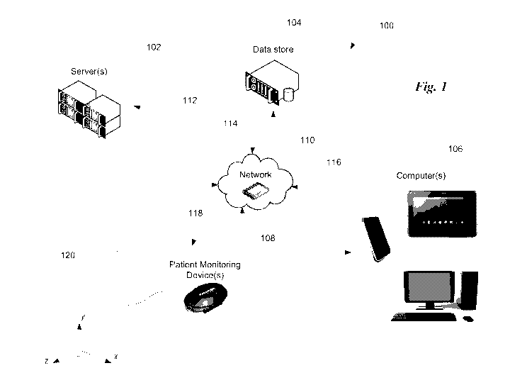
Illustrated in Fig. 1 is one example of components that may be included in a
patient monitoring system 100. Patient monitoring system 100 may include a
patient monitoring device 108 for detecting movements, combinations of
movements, positional changes, and other patient related activities or events
that
may indicate a patient is about to fall. Monitoring device 108 may be coupled
to a
patient 120, for example, in a belt, an ankle bracelet, an armband, or as part
of
article of clothing such as a sock, shirt, gown, and the like. Patient
monitoring
device 108 may communicate with a server 102, a data store 104, a computer
106,
and any other devices in the system using a communications link 118 and a
network 110. In one example, a computer 106 may be configured to discover what
patient monitoring devices 108 are nearby using network 110, and may be
configured to allow a caregiver using a computer 106 to select from which
patient
monitoring devices to monitor and receive alarm information.
Server 102 may communicate with other devices 104, 106, and 108 via
network 110 and communication link 112. Server 102 may be configured to
perform various tasks such coordinating the analysis and storage of alarm
related
information and/or storing and analyzing event or sensor data from devices
108.
Server 102 may be configured accordingly to accept event or alert information
from a monitoring device 108, and determine what caregiver(s) should receive
alerts for a given patient. Server 102 may make this determination based on
criteria
such as the caregiver's proximity to the patient, the patient's condition, the
caregiver's specialties, and the like. In this example, alerts sent from a
patient
monitoring device are sent to server 102 and distributed to the appropriate
caregiver when a patient monitoring device 108 indicates patient activity that
may
be outside the parameters set for that particular patient.
Data store 104 may be configured to store and provide access to
information obtained as a result of monitoring patient activity. Data store
104 may
include alarm information, patient activity data as captured by various
sensors in
patient monitoring devices 108, contact information and/or access credentials
for
CA 03030761 2019-01-11
WO 2018/013812 7
PCT/US2017/041934
caregivers, and/or a database of default patient profiles or profile parameter
information to name a few non-limiting examples.
As disclosed in further detail below, the patient monitoring device 108 is
configured to detect patient activity using various sensors, and to analyze
that
activity in real time to determine if it indicates a patient is likely to
stand or fall. If
a potential stand or fall event is detected, the monitoring device can send an
alert
notifying the server 102. The server can broadcast the alert to all or a
subset of
nearby caregivers giving them the opportunity to provide assistance before the
patient falls.
Responding caregivers can also indicate whether the alert was warranted by
communicating the patient's current situation back to the server using a
computer
106 such as a tablet, smart watch, or smart phone. The server can use data
store
104 to store this feedback from the caregiver, along with data values
collected in
real time by the monitoring device in the moments leading up to the alert.
This data
.. can then be analyzed by server 102 to determine what adjustments to the
logic or
configuration of the monitoring device should be made, if any, to increase the
system's accuracy in predicting patient falls. The system's overall accuracy
is thus
improved by facilitating feedback from caregivers about whether the predicted
fall
was actually about to happen, actually did happen, or that a patient fell
before any
alert was raised.
Additional detail of the software, hardware, and data aspects of a system
like the one illustrated in Fig. 1 is further illustrated in figures 2-6. Fig.
2 illustrates
at 200 one example of an arrangement of components for a patient monitoring
device like monitoring device 108. Monitoring device 108 may generally include
hardware 202, software 204, and may also include a local data store 206. Any
suitable arrangement of hardware or software modules may be used.
Hardware 202 may include a processor 208 which may be programmed to
perform various tasks discussed herein related to monitoring patient activity.
Processor 208 may be coupled to other aspects of hardware 202 such as sensors,
memory, and the like to perform these tasks. Memory 202 may be included for
storing operating values or parameters which may include intermediate or final
values of calculations, logical or computational instructions for processor
208, or
CA 03030761 2019-01-11
WO 2018/013812 8
PCT/US2017/041934
hardware control parameters. Memory 202 may also store patient monitoring
information such as patient related events in an event log 238, sensor data
236
obtained from sensors coupled to the patient monitoring device, and/or patient
profiles 244 for controlling how data about patient activity is collected and
analyzed. Memory 202 may be either a permanent or "static" memory, or a
temporary or "dynamic" memory, or any combination thereof.
An antenna 212 may be included to facilitate wireless communications over
a communication link like communication link 118. A networking interface 216
may be included to process communications with other devices in the system
communicated using a network such as network 110. Wireless transceiver 214 may
be included and may use antenna 212 or other suitable hardware 202 to transmit
and receive information between patient monitoring device 108 and other
devices
in the patient monitoring system such as server 102, data store 104, and/or
computer 106.
Patient monitoring device 108 may include one or more sensors such as a
motion sensor 218 configured to detect a patient's movements. Motion sensor
218
may be any suitable device or devices responsive to the movement of the
patient
and may include, for example, one or more accelerometers to detect movement in
multiple axes relative to gravity, and/or one or more gyroscopic sensors for
detecting changes in angular momentum and/or an angle of elevation. Motion
sensor 218 may be used to detect when a patient changes position to get out of
bed,
or abruptly falls to the floor from a standing position, or from a supporting
structure such as a bed, chair, wheelchair, and the like.
Hardware 202 may also include proximity sensor 220 configured to
generate signals based on distance from a target object or location. For
example, a
sensor target object such as a magnet, a radio transmitter, or other target
may be
positioned in or adjacent to a chair or bed, or other reference point.
Proximity
sensor 220 may determine the distance between sensor 220 and the sensor target
and provide this information as a time varying signal to other software or
hardware
components of patient monitoring device 108. For example, this proximity data
may be processed by processor 208 according to software 204 and used to
CA 03030761 2019-01-11
WO 2018/013812 9
PCT/US2017/041934
determine when a patient has traveled beyond a predetermined threshold
distance
from the sensor target as defined in the patient's profile.
A pressure sensor 224 may also be included, and may be useful for
detecting changes in the distribution of pressure on a patient's body. For
example,
pressure sensor 224 may detect an increase in pressure in one body part, and a
decrease in pressure in another as a patient moves from laying down to being
seated upright. Pressure sensor 224 may also detect rapid drop in pressure on
a
particular body part when a patient is falling, and a subsequent rapid
increase in
pressure when the patient lands abruptly on a support surface such as the
floor or
the ground.
The temperature sensor 222 may also be included to provide further
information about patient's location, position, and/or overall health. For
example
temperature sensor may be useful for determining when a patient removes the
sensor from their body, when a patient moves outside a facility, or enters an
environment that causes a large change in the patient's temperature, or in the
temperature of the environment.
Any of the sensors used by patient monitoring device 108 such as sensors
218, 220, 224, 222, and others, may be mounted inside or outside a housing
containing some or all of the other hardware and software components. For
example, patient monitoring sensors may be mounted outside a container or
housing and may communicate with hardware and software inside the housing by
any suitable communications link. For example, pressure sensor 224 may be
woven into a patient's clothing such as into a sock or gown, and may
communicate
with components of software 206 and hardware 202 mounted inside the housing
via a wired or wireless communications link. This communications link may be
maintained as electromagnetic signals traveling over wire leads, or through
the air
as radio waves using any suitable wireless communication technology.
These hardware aspects of patient monitoring device 108 may be
configured to operate according to instructions included in software 204.
These
instructions may be logically or conceptually arranged as modules for
controlling
different functional aspects of the patient monitoring device. Functional
aspects
generally include obtaining, storing, and processing data from multiple
sensors,
CA 03030761 2019-01-11
WO 2018/013812 10
PCT/US2017/041934
detecting patient activity, determining when to send alert notices to other
parts of
the system, retrieving or updating patient profile information, and/or sending
sensor data to a central archive to improve the performance of patient
monitoring
devices throughout the system.
Software 204 may include an alarm module 226 configured to send alarm
related messages, events, or data to other parts of patient monitoring system
100.
Alarm module 226 may determine when to send alert information notifying
caregivers when a change in a patient's situation warrants immediate
investigation.
Alarm module 226 may include rules for determining under what circumstances an
alert should be sent. In one example, alarm module 226 uses a patient profile
244
that has one or more patient related parameters with corresponding
predetermined
threshold values. These values may be used to determine when patient activity
warrants further investigation.
Examples of alarm rules include a pressure rule that is triggered when
signals are received from alarm module 226 that indicate changes in position
or
other activity that may have caused pressure differentials in the patient's
feet or
other monitored locations that are outside the predetermined threshold values
in a
patient profile 244. Such pressure sensor rules, when triggered, configure
patient
monitoring device 108 to send an alert indicating that changes in the pressure
distribution of a patient's weight relative to a support surface no longer
match the
predetermined patient profile. In one example, the patient has been prescribed
bed
rest resulting in a predetermined target distribution of weight across the
patient's
back and legs stored in patient profile. This weight distribution may be
periodically
or continuously detected by pressure sensor 224 as signals sent from the
pressure
sensor to other parts of patient monitoring device for processing and storage.
When
a patient moves, such as to an upright seated position, pressure sensor 224
may
begin sending different signals indicating a different distribution of weight
that no
longer matches the patient's profile. A rule in alarm module 226 may then be
triggered to send data, message, an event, or any other suitable series of
instructions or data to other parts of the patient monitoring system
indicating that
the patient has changed position.
CA 03030761 2019-01-11
WO 2018/013812 11
PCT/US2017/041934
In another example, alarm module 226 may include motion rules that may
be triggered when motion sensor 218 indicates movement that falls outside the
predetermined threshold values in patient profile 244 that are related to
motion.
Such motion related parameters in the patient profile 244 may include any
combination of movement in general areas such as the patient's extremities,
torso,
or in specific areas such as movement of the head and neck, movement of an arm
and/or leg, and the like. Such movement may include changes in the speed,
acceleration, or angle of incidence relative to gravity for a give part of the
patient's
body. Patient profile 244 may be stored in memory 210 along with other
relevant
data and may be used to maintain these parameters which may be generic to many
patients, or specific to the particular patient wearing monitoring device 108.
In another example, the alarm module 226 may include proximity rules that
are triggered when a patient travels beyond a predetermined distance from a
target
location such as a bed, chair, or other supporting surface. For example,
proximity
.. sensor 220 may send signals continuously or at regular intervals to patient
monitoring device 108 indicating the range to the target object. When the
patient
moves, proximity sensor 220 may send different signals indicating a change in
distance to the sensor target. The rule in alarm module 226 may be triggered
to
send information to other parts of the patient monitoring system in the event
that
proximity sensor 220 indicates a range from the sensor target that exceeds a
predetermined threshold in the patient's profile 244.
In yet another example, alarm module 226 may include motion sensor rules
that when triggered, configures patient monitoring device 108 to send alerts
when
the patient's movements do not match the patient's profile. Using motion
sensor
218, patient's movements may be periodically or continuously processed by
patient
monitoring device 108 as signals from the motion sensor change over time. At
some point, patient's movements may change causing motion sensor 218 to send
signals indicating a movement or series of movements that no longer match the
patient's profile. A motion sensor rule in alarm module 226 may then be
triggered
to send event data to other parts of the patient monitoring system indicating
that
the patient's movements suggest activity that is outside the patient's
predetermined
thresholds in the patient's profile and thus may be or detrimental to the
patient.
CA 03030761 2019-01-11
WO 2018/013812 12
PCT/US2017/041934
Alarm module 226 may be programmed with any suitable series of rules
comparing the current state of patient monitoring device 108 to one or more
predetermined threshold values. For example, alarm module 226 may include
rules
that are triggered based on combinations of input from multiple sensors
received
over time. These combinations may be defined in a monitoring rule, or in
patient
profile 244. In this way, one or more combinations of signals from one or more
sensors may be considered over specific time intervals allowing for more
complex
considerations of data received from motion sensor 218, pressure sensor 224,
temperature sensor 222, proximity sensor 220, and any other sensors that may
be
employed.
In another example, alarm module 226 may be configured with one or more
status related rules. Such rules may include a wireless networking rule
configured
to trigger when wireless transceiver 214 reports signal strength from nearby
wireless devices has fallen below a predetermined threshold. Another status
rule
may include a battery monitoring rule configured to trigger when the state of
charge for a battery 240 is below a predetermined threshold. Others such
status
rules may include an error reporting rule configured to trigger when a
hardware or
software error condition occurs, when available storage capacity in memory 210
is
below a predetermined threshold, and the like.
Alarm module 226 may also be programmed to include an alert level,
severity level, level of importance, or other similar flag or indicator to
assist the
patient monitoring system in prioritizing, categorizing, or managing the
response
to alarms or alerts that may be raised. Alarm module 226 may include rules for
calculating this priority level. For example, an alarm rule may be configured
to set
the severity level of an alarm to indicate a high degree of importance in the
case
where a particular threshold value (e.g. patient's movements) exceeds
parameters
set in the patient's profile by greater than a predetermined severity level
threshold.
Priority levels may be indicated in any suitable fashion such as a range of
numbers
zero through nine or zero through a hundred and the like, or a "high",
"medium",
and "low" indicator.
For example, if a patient's movements exceed parameters in the patient
profile by less than 10%, alarm module 226 may generate an alarm with the
CA 03030761 2019-01-11
WO 2018/013812 13
PCT/US2017/041934
severity level that is at a lower level such as zero or one or "low". When the
patient's movements exceed the upper range of a patient's profile by for
example
10-30%, a higher level may be assigned such as a three, or four or a "medium"
indicator may be used. For situations where patient movement exceeds the
patient's profile parameters by greater than 30%, a "high" indication may be
assigned to the alert information, or a value such as eight or nine. This is
but one
non-limiting example as any suitable scheme for prioritizing alarm information
may be used.
Profile module 228 may be configured to accept or modify or otherwise
maintain a patient profile 244. Patient profile 244 may include multiple
parameters
detailing information about the patient, the patient's treatment plan, and
other
information useful to patient monitoring device 108 and the rest of patient
monitoring system 100. A patient profile may include any information about the
patient useful for predicting and preventing patient falls. Such information
may
.. include detailed patient measurements such as medical condition, height,
weight,
body composition, treatment plans, drug regimens, and the like. It may also
include
demographic information such as sex, race, and the like.
For example, a patient profile may include parameters indicating whether a
patient should be allowed to move away from a supporting surface such as a bed
or
chair, whether the patient should be allowed to assume a particular posture or
position such as standing, walking, sitting, laying down (left and/or right
side), and
the like. A patient's profile may indicate under what circumstances a patient
may
leave the room, or how often the patient should be repositioned in place.
Parameters, or parameter ranges may be specified in any suitable format
such as numbers, letters, binary data, and the like. For example parameters
may be
organized to correspond with input values required by one or more rules in
alarm
module 226. In another example, patient parameters may be configured to
correspond with output ranges of specific sensors or combination of sensors
used
by patient monitoring device 108. The patient parameters may be thought of as
predetermined threshold values that may be compared to sensor or other data
according to a rule. These predetermined threshold values may be specific
values
CA 03030761 2019-01-11
WO 2018/013812 14
PCT/US2017/041934
or ranges of values, with or without accompanying tolerances. Such values may
be
numerical, textual, or any combination thereof.
An event capture module 230 may be configured to collect available event
related information to send out to other parts of patient monitoring system
when an
event occurs. This information may include a snapshot of the patient's present
condition and state as determined by the sensors in patient monitoring device
108.
A current reading from the motion sensor 218, proximity sensor 220, pressure
sensor 224, temperature sensor 222, and/or the state of various subsystems in
patient monitoring device 108 such as battery 240, memory 210, or any
combination thereof. Event data may also include the rule triggered, date and
time
stamp, and the like.
Event capture module 230 may collect event information when alarm is
triggered, or periodically to provide patient monitoring system 100 with an
ongoing regular status update of the patient's condition, position, activity,
and the
like. Event capture module may include rules specific to general event capture
irrespective of whether an alarm state has occurred. For example, an event
capture
rule may store event information in an event log 238 in memory 210 when
patient
activity occurs but is not outside the parameters specified for such activity
in
patient profile 244. This may be advantageous in providing "baseline" values
for
the state of a patient leading up to an alarm condition when it occurs. Event
data
may be stored in event log 238 and transferred to data store 104.
Other contextual information may be collected as well and sent along with
an alert or event update. Such contextual information may include signals or
other
data received from sensors or other parts of patient monitoring device 108 for
a
predetermined time period prior to the alert being sent. For example the alarm
module may collect all data obtained or received by patient monitoring device
108
for the last 60 seconds before the alert was sent, for the last five minutes
before the
alert was sent, for the last half an hour, or for some period of time greater
than a
half an hour. In another example, the transmission of data may be based on a
number of events rather than a specific period of time. This data may include
all
available monitoring data, or some portion of the data as determined by the
triggered rule, or by alarm module itself to 226.
CA 03030761 2019-01-11
WO 2018/013812 15
PCT/US2017/041934
In one example, when a motion sensor rule is triggered, the rule may be
configured to collect the preceding two minutes of motion sensor data and/or
the
preceding five minutes of pressure sensor data to be sent with the alarm
message.
In another example, alarm module 226 may be configured to collect the
preceding
five minutes of data from some sensors (e.g. pressure sensor, proximity
sensor, and
or motion sensor) but not others (e.g. temperature sensor). In another
example,
stored data from all sensors may be collected by 226 after a predetermined
number
of events have been detected and stored from a number of different sensors.
This
kind of "pre-alarm" data may be used by other parts of patient monitoring
system
to detect patterns of sensor data that indicate certain patient activity is
imminent or
to determine probabilities of false positives and false negatives. This
information
can be used to refine when rules should trigger.
Assembled data may be organized into an alarm message which may
include the current snapshot of the patient's condition and any other
information
related to the alarm that may be useful to other parts of the patient
monitoring
system. The message may be transmitted over a communication link using
networking interface 216 to be processed by a server such as server 102, or
seen by
an operator at a computer such as computer 106. The data may be stored in data
store 104 along with associated sensor data.
Control module 232 may be included to organize the operations of software
204 and/or hardware 202. Control module 232 may be configured to initialize
the
activity of patient monitoring device 108 such as going through a basic
startup and
testing procedure, running through algorithms or subroutines to locate and
communicate with server 102, data store 104, computer 106, and or other
devices
in the patient monitoring system. Control module may then begin one or more
control loops periodically or continuously obtaining sensor data from one or
more
sensors in the patient monitoring device such as pressure sensor 224, motion
sensor
218, proximity sensor 220, and or temperature sensor 222 or others. Control
module 232 may be thought of as a "controller" that controls the operation of
patient monitoring device 108.
A communication module 234 may be included as well. Communication
module 234 may be configured to open and maintain communication links to
CA 03030761 2019-01-11
WO 2018/013812 16
PCT/US2017/041934
various other parts of the patient monitoring system such as server 102, data
store
104, and others. Communication module 234 may be configured to implement any
suitable digital, analog, or other communication scheme using any suitable
networking, or control protocol. Communication module 234 may engage or use
networking module 242 to open, maintain and manage communication links with
other aspects of the patient monitoring system via network.
In one example, communications module 234 may be configured to
automatically establish communication link 118 with network 110. Patient
monitoring device 108 may be configured to operate according to the IEEE
802.15
wireless networking standard (sometimes referred to as a "Bluetooth" or
Wireless
Personal Area Network or "WPAN"). In this example, communications module
234 may automatically interact with routers, switches, network repeaters or
network endpoints, and the like to establish a communications link 118, and/or
112
so that event updates may be automatically configured to pass to server 102
where
they may be processed and distributed. Communications module 234 may be
implemented to use any combination of Generic Access Profile (GAP), Generic
Attribute Profile (GATT), and/or Internet Protocol Support Profile (IPSP)
protocols to acquire and maintain communications with server 102, data store
104,
and/or computers 106.
Monitoring device 108 may maintain data 206 which may include sensor
data 236, event log 238, and one or more patient profiles 244. Data 206 may
include diagnostic information, timestamps and other contextual information
related to actions taken by patient monitoring device 108, alarm messages
sent,
raw sensor data, and the like. Data 206 may be accessed by other software or
hardware in patient monitoring system 108. Data 206 may be periodically
refreshed or deleted to optimize use of memory 210.
Stored patient profiles 244 may include default parameter values general to
many patients, or parameter values specific to one patient. These parameter
values
may be refreshed periodically from time to time such as by a firmware upgrade,
by
replacing a memory card, or via communications link 118. Profile parameters
may
be analyzed and processed on another computer such as server 102 and
periodically sent to patient monitoring device 108.
CA 03030761 2019-01-11
WO 2018/013812 17
PCT/US2017/041934
One example of software and hardware components that may be used to
implement a server such as server 102 is shown in FIG. 3 at 300. Server 102
may
include any suitable combination or arrangement of hardware and software. For
example, server 102 may include a processor 304 that can be configured or
programmed to perform calculations related to generating and maintaining
patient
profiles, maintaining current locations for patients being monitored,
receiving and
propagating alarm or event information, and/or analyzing historical results
from
previous alarm situations. Other components in the system such as computers
106,
patient monitoring devices 108, and data store 104 may communicate with server
102 to collect and or receive this information as events unfold for the
patients
being monitored.
Communication between server 102 and other parts of the system using
communications links may be facilitated by transceiver 314. For example,
communications links 112, 114, 116, and 118 may be implemented via any
suitable
wireless technology such as WiFi, Bluetooth, and others using transceiver 314
and
antenna 308.
Server 102 may include user 1/0 devices 310 which may include any
suitable devices for accepting input from a user such as keyboards, mice, or
other
1/0 devices. For example, devices 310 may include a touchscreen, one or more
buttons or other controls on a control panel coupled to or integrated with
server
102.
Server 102 may include a networking interface 312 for communicating
with other parts of the patient monitoring system such as the data store 104,
computers 106, and the like. Interface 312 may interact directly with network
110
through a wired or wireless communications link. For example, a communications
links like communications link 112, 114, 116, and 118 may connect server 102
to a
computer 106. A memory 306 may be included as well for temporarily or
permanently storing sensor data, profile data, logical or computational
instructions,
and the like.
A display device may be included as well for displaying a user interface
such as a Graphical User Interface (GUI) generated by server 102. The GUI may
include graphical controls for managing or maintaining aspects of server 102
CA 03030761 2019-01-11
WO 2018/013812 18
PCT/US2017/041934
and/or other components of the patient monitoring system. For example, the GUI
may be configured with controls for calculating or generating new patient
profiles,
manually overriding alert messages sent from a patient monitoring device 108
(e.g.
marking a result as a "false positive" or "false negative"), upgrading
software in
server 102, in patient monitoring devices 108, and/or in computers 106.
Display
device 316 may be a touchscreen programmed to perform these or other tasks
using any suitable configuration of text, graphics, and/or GUI controls such
as
check boxes, drop-down lists, text fields, buttons, and the like useful for
accepting
input and displaying output.
Software components of server 102 may include a patient event module
338 which may configure processor 304 and other components of server 102 to
process information about activities or events taking place with monitored
patients.
Event or alarm messages may be generated by patient monitoring device 108 and
may include about a patient's disposition as detected by a patient monitoring
device 108.
For example, as discussed herein elsewhere, patient monitoring device may
detect the patient has changed position from a laying down to sitting up,
rolling
from the left side to a right side or vice versa, has begun to walk around a
room, or
has fallen from a support surface such as a chair or bed. Event module 338 may
be
configured to receive these events or alarms, and determine how they should be
processed and/or stored by server 102. For example patient event module may
configure server 102 to communicate event data to data store 104 for long-term
storage or future processing. Patient event module 338 may also configure
server
102 to communicate with other computers such as computers 106 operated by
caregivers and others.
Event capture module 230 in a patient monitoring device 108 may
communicate event or alarm messages to patient event module 338 as they occur.
For example, patient monitoring device 108 may collect information with one or
more sensors such as a motion sensor 218 and the like, and may determine by
rules
in alarm module 226 that the event does not fall outside profile parameters in
the
patient profile. Thus no alarm may be generated. However, event capture module
230 in the patient monitoring device 108 may deliver the event information to
CA 03030761 2019-01-11
WO 2018/013812 19
PCT/US2017/041934
server 102 where it may be received by and processed by patient event module
338. Patient event module 338 may store, process, or otherwise perform logic
functions on the event as well. In this way, patient monitoring device 108 may
maintain periodic or nearly constant communication with server 102 collecting
information about patient activities which may be processed in the future to
detect
false positives, false negatives, or otherwise refine the event collection and
alarm
process to better ensure patient safety and adherence to treatment plans.
When alarm module 226 in the patient monitoring device determines that
patient activity is outside the predetermined thresholds in the current
patient profile
.. 244, an alarm or alert may be generated by patient monitoring device 108
which
may be communicated to server 102 and handled by alarm module 326. Alarm
module 326 may process the alarm information received from patient monitoring
device 108 according to one or more processing rules for handling the alarm.
For example, rules in alarm module 326 may be configured to process and
route alarm information through communications link 116 to one or more
computers 106. These rules may use any information in an alarm or event to
determine which computers associated with particular caregivers are to receive
information. For example, the information may be routed based on severity
level
included in the alarm with "high" priority alarms sent to multiple individuals
so
.. that these individuals can converge on the patient to provide faster
assistance. In
another example, an alarm may be sent a single individual regardless of
severity.
The information in the alarm may be presented to the user of computer 106 by
any
suitable means such as a GUI on a display device that may include text,
graphics,
symbols, or flashing regions of the screen etc. Sounds, flashing lights,
vibration,
automatically generated and automatically generated phone calls are other
notification methods that may be used. Any suitable notification means may be
employed.
Alarm module 326 may include one or more notification rules useful for
determining what contacts to notify with specific alarm information and under
what circumstances to do so. Alarm module 326 may also access a database of
contact information in data store 104 when a rule is triggered indicating a
specific
contact who is to receive specific alarm information for a given alert. Alarm
CA 03030761 2019-01-11
WO 2018/013812 20
PCT/US2017/041934
module 326 may communicate the information using any suitable method such as
by e-mail, by automated telephone call, by a Short Message Service (SMS)
"text"
message, by a push notification to an app on a personal computing device such
as a
cell phone, smart watch, or tablet and the like.
In another aspect, alarm module 326 may be configured to maintain
information about alarm rules used by alarm module 226 in patient monitoring
device 108. Alarm module 326 may be configured to accept input from computer
106, or elsewhere, adjusting how and when the rules trigger alarms based on
the
various parameters in a patient profile 244. These rule upgrades may then be
sent
to a specific patient monitoring device 108, or to all such patient monitoring
devices thus allowing the behavior of the monitoring devices to be upgraded
and
improved.
A communication module 322 may be included in server 102.
Communication module 322 may operate like communication module 234 in
patient monitoring device 108. Module 322 may be configured to open and
maintain communication links to various other parts of the patient monitoring
system such as server data store 104, patient monitoring device 108 and
others.
Communication module 322 may be configured to implement any suitable digital,
analog, or other communication scheme using any suitable networking, control,
or
communication protocol. Communication module 322 may engage or use
networking module 312 to manage communication with other aspects of the
patient
monitoring system via network 110 and any communications links that may be
involved.
Location finding module 324 may be included and may configure server
102 to collect, analyze, process, and/or maintain information in real time
indicating
the location of patients, caregivers, or other people and objects. Such
location
information may be used by the system in order to route alert information to
the
proper caregivers. For example, alarm module 326 may collaborate with location
finding module 324 and use patient and caregiver contact information from data
store 104 to determine the closest qualified caregiver to notify when an alarm
is
issued. Location finding module may use any suitable technology whether
internal
or external to the patient monitoring system for tracking the location of
people and
CA 03030761 2019-01-11
WO 2018/013812 21
PCT/US2017/041934
objects such as Global Positioning System (GPS) and/or Real-Time Location
System (RTLS), and the like.
5oftware304 may include heuristics module 318 which may configure
server 102 to make adjustments to patient profiles based on input from
caregivers,
past events or alarms, ongoing monitoring of events as they occur, and the
like.
Adjustments to patient profiles may be made based on past information to
better
anticipate or predict situations where an alarm should be issued more often,
lest
often, or not at all. Server 102 may process this information substantially
continuously during normal operation as new data is collected from patient
monitoring devices, and as alerts are raised and feedback from caregivers is
received.
In one example, heuristics module 318 may send variable profile updates
for one or more patient profiles if multiple false positives, or false
negatives are
encountered during treatment. For example, patient monitoring device 108 may
sense motion or pressure relative to a support surface that falls outside
parameters
in the patient's profile causing an alarm message to be sent. After observing
the
patient, a caregiver may determine that the alert was a false indication of a
potential patient fall when the likelihood of a fall was actually very low
(i.e. below
a predetermined threshold). Heuristics module 318 may receive this information
from a computer 106 which may include data collected at the time of the event.
Heuristics module 318 may then analyze the data and adjust parameters in the
patient's profile accordingly to reduce or eliminate the number of similar
future
false alarms for that particular patient, and possibly for all other similarly
situated
patients. These adjustments to other patient monitoring devices may occur in
real
.. time as soon as the data can be analyzed after the alert has been handled
by
caregivers.
In another example, the heuristics module 318 may be used to calculate
thresholds for one or more standard or default profiles based on patient and
demographic data and "pre-alarm" or other information available for an alarm
event. The heuristic module may, over time, collect a large body of sensor
data,
event data, alarm information, demographic information, and the like which may
be used to refine thresholds in patient profiles or in default profiles, to
better align
CA 03030761 2019-01-11
WO 2018/013812 22
PCT/US2017/041934
the parameters that may generate an alert with the patient, the patient's
history, and
the patient's treatment plan.
In another example, the heuristics module may be used to determine that
changes to the functional aspects of alarm rules used by alarm module 226 in
patient monitoring device 108 may be beneficial to avoid excessive false
alarms.
Heuristics module 318 may determine from analyzing alarm data over time that
certain alarm rules are causing excessive false readings and should be
reviewed
and/or removed from alarm module 226.
A patient profile generator module 320 may be included for creating patient
profiles that may be used by other devices in the system such as patient
monitoring
device 108. Profile generation module 320 may create the profile, and deliver
it to
a patient monitoring device 108 via communications links 112 and 118, and
network 110.
Profile generator 320 may be used when the system begins monitoring a
patient, or at any other suitable time such as when a new profile is needed
for any
reason. An "initial" or "default" profile may be selected initially to provide
a
template or baseline profile that profile generator module 320 may use in
tailoring
the profile to the patient. The system may include multiple "default" profiles
specific to any number of parameters or aspects. For example, the system may
have separate default profiles for men, for women, or multiple profiles for
men and
women specific to various age ranges, races, medical histories, drug
therapies, and
the like. Any patient data may be considered in selecting and generating a
profile
such as data about any medical conditions a patient may have that may be
detected
by the patient monitoring device.
For example, a person with a neuromuscular disorder, or other disorder,
that causes regular periodic movement of an arm, leg, or neck may benefit from
an
initial profile with parameter threshold values that take this kind of
movement into
consideration. These threshold values may thus configure patient monitoring
device 108 to adjust its threshold values to account for movement specific to
the
patient's particular condition so that extraneous movements common to people
with the patient's condition are ignored
CA 03030761 2019-01-11
WO 2018/013812 23
PCT/US2017/041934
Profile generation module 320 may also configure server 102 to accept
input selecting an appropriate "default" profile, and additional input from a
caregiver using server 102 or another computer such as computer 106 to tailor
the
profile to a particular patient's specific needs. Customizing the profile may
include
importing or entering aspects of a patient's treatment plan, or entering
details
specific to the patient's condition that are not provided in the default
profile, or
differ from the threshold settings provided by the default profile.
Fig. 4 illustrates at 400 one example of a data store or knowledge base 104
that may be part of the patient monitoring system to store information. Though
the
.. patient's identity need not be revealed, data store 104 may include patient
data 408
having patient records with detailed information about the patient's medical
history, treatment plan, demographics, and the like. Sensor data 406 may be
included for storing various pressure, motion, proximity, and other data
collected
or processed by patient monitoring devices 108. Data store 104 may include
event
.. data 404 with detailed information captured by patient monitoring device
108,
server 102, and computers 106 when an event occurs. Event data may include or
refer to other information such as sensor data 406, patient data 408, as well
as
information about the decision making process leading up to the event being
created and sent. For example, event data 404 may include the sequence and
selection of rules that were triggered causing the event to be sent. It may
include
other data such as a patient's vital signs before, during and after the event,
which
caregivers responded, how long it took them, how far they had to come to lend
aid,
and the like.
Data store 104 may also include contact information that can be used by the
patient monitoring system to contact information for various individuals or
other
devices/systems that can have notification information sent to them. Contact
information in the contact database 354 may include names, addresses, email
addresses, telephone numbers, Internet Protocol (IP) addresses, web service
URLs,
or any other suitable information useful for contacting an entity interested
in
.. receiving event notification information. Server 106 may receive and
process
events from multiple monitoring devices 108. Once processed, the notification
information may be sent to contacts specified in contact database 410. These
CA 03030761 2019-01-11
WO 2018/013812 24
PCT/US2017/041934
contacts may receive the notification information for one or more events using
a
personal or mobile computer 106.
A computer or other electronic alert device like computer 106 may be used
by caregivers to receive alert information from server 102 or personal
monitoring
devices 108. Such a computer, or similar alert device, may also be used in
proximity to a patient, such as in the patient's room, or worn as an arm band
to
notify the patient that their movements may lead to a fall. One example of the
software and hardware aspects that may be included in computer 106 is
illustrated
in Fig. 5 at 500. Hardware 502 included in computer 106 may be configured
according to instructions included in software 504 controlling the computer to
receive alarm information, make the information in the alarm available to a
user
such as a caregiver, and allow the caregiver to respond accordingly in a
timely
fashion.
Hardware 502 may include a processor 506 which may be programmed to
perform various tasks discussed herein related to monitoring patient activity.
Processor 506 may be coupled to any other aspects of hardware 502 such as
memory 508, networking interface 514, and others. The functions performed by
processor 506 may be configured according to instructions encoded in software
504, or in hardware 502.
Computer 106 may include user 1/0 devices 518 which may include
hardware and/or related software for managing input and output with devices
518.
These devices may include equipment such as keyboards, mice, touchscreens,
intelligent voice recognition and the like. A network interface 514 may be
configured to interact with networks like network 110 via communications links
like links 112, 114, 116, and/or 118. A display device 540 may be included as
well
for displaying a user interface generated by computer 106. With many tablet,
smart
phone, smart watch, or desktop personal computing devices, display device 540
may be a touchscreen making it part of the user 1/0 equipment 518 as well.
A memory 508 may be included as well for temporarily or permanently
storing data values or instructions and the like. Computer 106 may also
include a
wireless transceiver 512 which may include hardware and/or software
implementing a wireless communication interface. Wireless transceiver 512 may
CA 03030761 2019-01-11
WO 2018/013812 25
PCT/US2017/041934
be coupled to an antenna 510, and may include a transmitter, receiver, and/or
other
useful equipment configured to send and receive signals. In this respect,
wireless
transceiver 512 may be useful for maintaining a wireless communication link
such
as link 116 and may interact with network interface 514 as necessary to
receive
and send information. Wireless transceiver 514 may also be useful for sending
and
receiving cellular telephone calls such as telephone calls, text messages, and
the
like.
Hardware 502 may also include a location finding system 516 that may use
any suitable technique for obtaining a physical location for computer 106. The
location-finding system may use any combination of other hardware and software
to accomplish the goal of maintaining accurate and precise positional
information.
Wireless transceiver 512 and antenna 510 may be used to triangulate the
position
of computer 106 based on communications with various transmitters and
receivers
in the area.
For example, location finding system 516 may determine the location of
computer 106 based on communications with beacon transmitters and/or
networked receivers positioned in known locations around the environment to be
monitored. These transmitters and receivers may be included in networking
equipment operating as part of a local wireless network that conforms to
Institute
of Electrical and Electronics Engineers (IEEE) 802.11 wireless networking
standards (sometimes referred to as a "WiFi" or a Wireless Local Area Network
or
"WLAN"). In another example, these transmitters and/or receivers positioned in
the environment may include devices that operate according to the IEEE 802.15
wireless networking standards (sometimes referred to as a "Bluetooth" or
Wireless
Personal Area Network or "WPAN"). Other technologies may be useful as well as
the satellite based Global Positioning System (GPS) or triangulation based on
interactions with cell tower transmitters and receivers that are part of a
cellular
network.
Software 504 may include various modules for configuring functional
aspects of computer 106. A user interface module 532 may be provided for
generating user interfaces with graphical buttons, windows, text boxes,
selection
boxes, and other widgets configured to gather data or elicit specific
responses from
CA 03030761 2019-01-11
WO 2018/013812 26
PCT/US2017/041934
the user which may be accessible using any suitable input device such as a
touch
screen, mouse, or keyboard. User interface module 532 may also display various
glyphs, figures, icons, graphs, charts, tabular displays, and the like which
may or
may not be modified or interacted with using any suitable input device. User
interface module 532 may be used in conjunction with other software modules to
provide navigational control between various presentations of information, to
accept character or selection input from an input device, and/or to generate
graphical displays of relevant data accessed by other software modules. User
interface module 532 may operate in conjunction with an operating system
installed on computer 106 which may include libraries of windowing widgets,
basic input/output capabilities, and basic file system and network interfaces
for
user interface module 532 and for other software modules as well.
User interface module 532 may use any suitable display technology,
programing language, toolkit, Application Program Interface (API), or protocol
to
create the user interfaces for computer 106. Module 532 may, for example,
interpret and display a dynamically or statically created web page sent from
server
102 as Hypertext Markup Language (HTML) and may include a web browser for
viewing the results. User interface module 532 may include an "app" or
application
operating as a client and connecting to server 102 over network 110 to
retrieve data
which is then displayed using graphical controls such as buttons, selection
boxes,
text fields, widgets, and the like.
In one example, user interface module 532 may include a graphical user
interface displaying alert information. This information may include an
indication
of the severity of the alert, the patient's name and/or location, an
indication of the
type of alert (e.g. a fall, change in position, excessive movement, etc.),
and/or any
other relevant information made available by a patient monitoring device or
any
other part of the monitoring system. A map of the local area may be included
as
well with indicia showing the patient's location in relation to the location
of
computer 106. In another example, the alert information may be configured to
exclude information identifying the patient. In yet another example, noise may
be
included in the data from the monitoring device to further obscure a specific
patient's identity.
CA 03030761 2019-01-11
WO 2018/013812 27
PCT/US2017/041934
Multiple response options may be presented by user interface module 532.
A responding individual may select buttons, checkboxes, enter text, or perform
other actions based on the options provided. For example, computer 106 may be
a
tablet computer, smart watch, or smartphone which may be carried by a
responder
to the patient's location. Upon inspecting the patient and the circumstances
surrounding the alarm, a responder may use the options presented by user
interface
module 532 to notify the patient monitoring system that a visual or other
inspection
of the patient, the patient's equipment or environment was performed. The user
interface provided may configure computer 106 to accept input indicating the
alert
.. was warranted and was due to patient movement or other activity that was
potentially detrimental. The user interface may be configured to accept input
indicating the alarm was not warranted and was due to, for example, an
equipment
malfunction or resulted from harmless or unintentional patient activity (e.g.
mistakenly or incidentally bumping the sensor while asleep, or otherwise
triggering
the alarm through harmless action). This information may then be passed to
server
102, data store 104, or to any other aspect of the patient monitoring system.
An access control module 520 may be included for identifying the user of
computer 106 according to one or more credentials and for controlling access
to
hardware and software aspects of the system. Such access control may include a
.. user interface generated by user interface module 532 which may include
buttons,
text fields, and other controls configured to accept credentials as input from
a user.
Such credentials may include a user name, password, answers to questions, and
the
like. Other examples may include credentials stored on a physical object in
the
possession of the user, such as a Radio Frequency Identification (RFID) tag,
Near
Field Communication (NFC) badge, card with magnetic strip , barcode, portable
memory device (e.g. Universal Serial Bus (USB) memory "stick" or plastic card)
containing a secret token or other encoded or encrypted information.
In another example, user credentials may include biometric input. Access
control module 520 may control a biometric input device which may be one of
user
I/0 devices 518. This device may be configured to measure or scan or accept
data
representing one or more physical characteristics of the user such as a
fingerprint,
handprint, iris, facial topography, word, phrase, or other vocalization, and
the like.
CA 03030761 2019-01-11
WO 2018/013812 28
PCT/US2017/041934
A location finding module 534 may be included and may configure
computer 106 to process information received by location finding system 516 to
determine the location of computer 106. This location information may be used
by
the system in order to route alarm information to the proper caregivers.
Location
finding module may also send the location information to other parts of the
system
such as server 102. This information may be distributed continuously and/or at
regular intervals and may be used to determine the location of the closest
qualified
caregiver when an alarm is raised.
An SMS module 526 may be included with software 504 for configuring
computer 106 to receive text messages distributed by server 106, or by others.
SMS module 526 may configure computer 106 to interact with other servers such
as SMS service centers or short message gateways to receive the SMS messages
specific to a particular personal computing devices 302. SMS module 526 may
interact with other modules such as user interface module 532 to display SMS
messages according to user preferences.
A push notification module 528 may be included with software for
configuring computer 106 to receive push notification messages distributed by
server 102, or by others. Push notification module 528 may configure computer
106 to interact with centralized push notification servers using network
interface
514, communications link 116, or other suitable communications links. Push
notification module 528 may interact with other modules such as user interface
module 532 to display push notifications according to user preferences. Push
notification module 528 may be configured to send and/or receive push
notifications according to any suitable protocol. Examples include, but are
not
limited to, Advanced Message Queuing Protocol (AMQP), Message Queue
Telemetry Transport (MQTT) protocol, and Simple/Streaming Text Oriented
Messaging Protocol (STOMP).
An e-mail module 542 may be included with software for configuring
computer 106 to receive email messages distributed by server 106, or by
others.
Email module 542 may configure computer 106 to interact with centralized
electronic mail servers using network interface 514, communications link 116,
or
other suitable communications links. Email module 542 may interact with other
CA 03030761 2019-01-11
WO 2018/013812 29
PCT/US2017/041934
modules such as user interface module 532 to display email messages as
specified
by the user.
Software 504 may include an alarm control module 522 which may be
included to configure computer 106 to receive alarm related messages, events,
or
data from other devices in the patient monitoring system 100 such as server
102.
Alarm control module 522 may use other hardware or software modules to display
and otherwise alert the patient or a caregiver that an alarm has been raised.
Alarm
control module may be configured according to user preferences, or according
to a
predetermined notification policy, to display any combination of visual,
audible,
tactile, or other notification of an alarm. Such notification may include a
push
notification appearing on a display device 540, an e-mail sent to a
caregiver's e-
mail address, an SMS message viewable using SMS module 526 or other SMS
client software in computer 106, an automatic telephone call, an alarm indicia
appear on display device 540 using user interface module 532, and/or an
audible
sound or ringtone being played, or any suitable combination thereof.
Alarm control module 522 may display details about the patient involved in
the alert by accessing patient information using patient information module
536,
and/or by accessing patient data 408 in data store 104. Information about the
patient, the alarm, and other related information may also be included in the
alarm
message sent from server 102. Alarm control module 522 may collaborate with
user interface module 532 to display this information to the caregiver
allowing
them to view specifics about the event, or activities that lead up to the
event. This
user interface may be configured to accept input from a user that may include
response options such as confirming the alarm is valid, declaring that it is
invalid,
making adjustments to the profile thresholds thus changing the behavior of
patient
monitoring device 108, and/or entering additional observations about the
patient,
the equipment, the treatment plan, and the like.
Networking module 538 may include software for configuring computer
106 to establish and maintain communication link 364. Networking module 538
may therefore configure processor 506, network interface 514, I/0 devices 518,
and any other suitable hardware or software in compute 106. Any suitable
protocols may be supported by networking module 538 such as Transmission
CA 03030761 2019-01-11
WO 2018/013812 30
PCT/US2017/041934
Control Protocol/Internet Protocol (TCP/IP), User Datagram Protocol (UDP),
Ethernet protocol, or any other suitable networking protocol. Any of these
protocols may be used to establish and maintain communications link 116 which
may then be used to interact with server 106. Put another way, server 106 may
use
any of these protocols, or any other suitable networking protocol to
distribute
information to computers 106, or to other recipient systems.
A communication module 530 may be included in computer 106.
Communication module 530 may operate like communication modules 234 and
322 in patient monitoring device 108 and server 102 respectively. Module 530
may
be configured to open and maintain communication links to various other parts
of
the patient monitoring system such as server data store 104, patient
monitoring
device 108 and others. Communication module 322 may be configured to
implement any suitable digital, analog, or other communication scheme using
any
suitable networking, or control protocol.
A patient event module 524 may be included in software 504 which may
configure computer 106 to process information about activities or events
taking
place with monitored patients. These events may be sent by server 102 or
patient
monitoring device 108, and may or may not involve emergency or alarm
situations.
As discussed above, patient events may be generated by patient monitoring
device
108 and distributed by server 102. These may include notifications about a
patient's movements, changes in position, and the like. Event module 524 may
be
configured to receive these and other events, and make them available to a
caregiver. A caregiver may view this information when an alarm is raised, or
at
other times to better ensure patient safety and adherence to prescribed
treatment
plans.
A patient information module 536 may be included with software for
configuring computer 106 to obtain and display patient information. Patient
information module 536 may configure computer 106 to interact with a
centralized
database of patient information such as data store 104 to obtain information
for
review, to edit information in the data store, to add new patient information,
or to
delete information that is incorrect or extraneous. Patient information module
may
interact with other modules such as user interface module 532 to display
patient
CA 03030761 2019-01-11
WO 2018/013812 31
PCT/US2017/041934
information messages upon request by a user, or with alarm control module 522
to
obtain and display patient information or links which display patient
information if
selected by the user.
An example of the patient monitoring system in operation is illustrated in
Figs. 6 and 7 at 600 and 700 respectively. At 602, the patient profile is
initialized.
This may be performed by a caregiver using a computer 106 interacting with
server
102 and data store 104. For example, computer 106 may display an access
control
interface created by user interface module 532 and/or access control module
520.
A user's access control credentials may be provided and authenticated against
contact information 410 in data store 104.
An initial portion of patient information may be retrieved using patient
information module 536 and user interface module 532 may display this
information in a profile generation or initialization interface. The profile
initialization interface may also be configured to accept input from a user
allowing
the user to select a default profile based on default profile options provided
by
patient profile generator module 320 in server 102. A user may provide input
selecting a profile and making any adjustments to the default values for the
profile
parameters to match the parameters to that specific patient and the patient's
treatment plan. When ready, the patient profile may be saved to patient data
408 in
data store 104, and sent to a patient monitoring device 108.
At 604, the patient monitoring device with the patient's profile may be
activated and "installed" or placed in an appropriate location to monitor the
patient's activities. Such appropriate locations include any location suitable
for
monitoring patient activity such as on or adjacent a patient's head, neck,
torso,
foot, arm, leg or other area. The monitoring device, or parts thereof, may be
installed in a bed, chair, or other supporting structure instead of, or in
addition to
being mounted on the patient. In one example, the monitoring device may be
worn
by the patient, and at least one of the sensors may be included in the
patient's
clothing such as in a sock or gown worn by the patient. It may be advantageous
to
positon the monitoring device, or any of the sensors associated with it, on a
patient's extremity such as in a sock worn on a foot, in an armband worn on
the
wrist, or on the head, knee, or elbow to name a few other non limiting
examples.
CA 03030761 2019-01-11
WO 2018/013812 32
PCT/US2017/041934
Such a position can result in more noticeable changes in position that may be
used
to more accurately predict when a patient is making movements that may result
in
a fall.
When activated, the patient monitoring device 108 may begin obtaining
sensor output at 606, and comparing the sensor output to the profile
parameters at
608. If the output is within the limits of the parameters at 610, the
monitoring
device continues monitoring sensor readings taken at 606. These sensor
readings
may be sent to server 102 and saved to data store 104. Server 102 may transmit
the
readings to a computer 106 periodically or continuously, or all computers 106
who
are configured to retrieve them.
When the output for a sensor falls outside the threshold values defined by
the parameters in the patient profile, an alert may be triggered at 612. The
alert
may be sent from alarm module 226 and received by server 102. Server alarm
module 326 may process the alert as discussed above, sending it to the
appropriate
caregiver's computer 106. User interface module 532 may then display details
about the alarm to the respective caregiver(s). If the alarm is confirmed to
be valid
at 614, the caregiver may provide input to that effect using computer 106. If
the
alarm is confirmed to be false at 618, the caregiver may acknowledge this as
well
using computer 106. The system may update the historical sensor and event
related
data at 620 allowing heuristic module 318 to refine profile parameter settings
for
future profiles to improve and refine the system's overall knowledge of
patient
behavior, and /or to better avoid false alarms in the future. Whether the
alarm is
valid or not, user interface module 532 may provide a caregiver with a profile
interface for adjusting a patient's profile parameters. Such adjustments may
be
made by sending the updated profile to server 102 and monitoring device 108 at
622 and the monitoring activities may continue at 606.
One example of the kinds of comparisons the system makes between the
sensor output and the profile parameters in the patient profile is illustrated
at 700 in
Fig. 7. At 702, the motion sensor in the monitoring device includes an
accelerometer. The monitoring device operates in a "low power" or "stand-by"
mode monitoring data from the accelerometer to detect movement of the patient
which is greater than or equal to a predefined activation threshold. In stand-
by
CA 03030761 2019-01-11
WO 2018/013812 33
PCT/US2017/041934
mode, the monitoring device may disable other sensors such as gyroscope
sensors,
pressure sensors, proximity sensors, and the like. The monitoring device may
also
disable wireless transceivers, network interfaces or other modules that may
consume additional power. In this example, as long as the accelerometer
activity is
less than the activation threshold at 704, the monitoring device maintains the
"stand-by" operating mode.
When the accelerometer indicates patient movement that exceeds the
activation threshold, the monitoring device moves from "stand-by" mode to
"full
monitoring" mode at 706. In this mode, additional modules, subsystems, or
other
aspects of the monitoring device may be enabled. Examples include a network
interface may be enabled to allow an alert to be transmitted over the network
110.
Other sensors may also be enabled at 708 such as one or more pressure sensors,
gyroscopic sensors, proximity sensors, and/or temperatures sensors. By
disabling
these sensors in "stand-by" mode, the monitoring device can conserve power. If
pressure, gyroscope, temperature, or other sensor data exceeds thresholds in
the
patient profile at 710, the alert is triggered at 612. Alternatively, the
monitoring
device may be configured to trigger an alert when the accelerometer data alone
has
exceeded the threshold.
The pressure sensor may be in a sock worn by the patient, and the pressure
sensor may generate a signal that is a time-varying voltage corresponding to
the
level of pressure the patient is exerting on the sensor. For example, when
laying in
bed, sitting in a chair, or in some other resting position where pressure is
at or near
a minimal value, the signal may be less than 800 mV. When the signal is at or
near
a maximum value for a given patient, such as when the patient is standing, the
signal may be over 1800 mV. These values may be tailored specific to a
particular
patient. For example, a lighter patient, such as a child, may not be heavy
enough to
generate 1800 mV. Therefore, the profile thresholds may be adjusted
accordingly
by the server when the profile is initially loaded into the monitoring device,
or later
by the caregiver using a computer 106 to adjust the values as needed.
The monitoring device may be programmed to perform more complex
analysis of the signal data received from the various sensors. Different
constant
values may be also applied to the sensor data to effectively "weight" certain
sensor
CA 03030761 2019-01-11
WO 2018/013812 34
PCT/US2017/041934
data, or combinations of sensor data more heavily than others. In one example,
the
monitoring device samples the signals from motion sensors such as an
accelerometer and a gyroscope, as well as signals from a pressure sensor. The
data
collected for each sample from each sensor may include a single value, or
multiple
values such as a value for three separate planes orthogonal to one another
(e.g.
"up/down", "left/right", and "forward/backward"). The values may be combined
according to a particular function to calculate a result that may be compared
with
an alert threshold to determine when the alert threshold has been met or
exceeded
and a caregiver should be notified.
In one example, the sensors may yield three individual overall acceleration,
pressure, and angular moment values for each of n evenly spaced samples at
separate times t. These individual values may be weighted using constants C1,
C2,
and C3, as follows:
y(t) = Cia + C2g + C3p
where:
t is the time the sample is taken
a is the value from the accelerometer at time t
g is the value from the gyroscope at time t
p is the value from the pressure sensor at a time t
In another example, the sensors may yield seven separate values at each
time t, six of which represent acceleration a and angular momentum g measured
at
time t in each of three corresponding directions that are orthogonal to one
another
(e.g. "up/down", "left/right", and "forward/backward"). The remaining value
may
be a pressure measurement p measuring pressure exerted by a patient's foot.
The
data collected might appear as follows:
3-axis Accelerometer data: a a a
x, 37, z
3-axis Gyroscope data: ga, gp, gy
Pressure data: p
CA 03030761 2019-01-11
WO 2018/013812 35
PCT/US2017/041934
An equation combining these values might then be:
y(t) = Ciax + C2ay + C3az + C4ga + C5gp + C6gy + C7p
where:
t is the time the sample is taken
aõ, ay,az, is the value from the accelerometer in the plane x, y, and z
respectively at time t
ga, gp,gy, is the value from the gyroscope in the plane a, /3, and y
respectively at time t
p is the value from the pressure sensor at a time t
In another example, the sensors may yield nine separate values at each time
t representing acceleration a, angular momentum g, and pressure measurement p
taken at a time t in each of three corresponding directions that are
orthogonal to
one another. The data collected may then be as follows:
3-axis Accelerometer data: a, a, a
x yz
3-axis Gyroscope data: ga,gp,gy
3-axis Pressure data: Pa,Pb,Pc
From these data values, a more sophisticated function may
be constructed employing many constants C which may be used to
apply a more granular weighting to the data from the sensors, or to
any permutation or combination of the data. One example of such a
function is:
y(t) = Ciax + C2ay + C3az + C4axay + C5axaz + C6ayaz + C7axayaz
+ C8ga + C8gp + Cloy + Cligagp + Ci2gagy + C13gfigy
+ Ci4gag figy + C15pa + Ci6pb + Ci7pc + C18papb + C18papb
+ C2oPbPc + C21PaPbPc
CA 03030761 2019-01-11
WO 2018/013812 36
PCT/US2017/041934
Constants C1 through C21 can be determined initially by experimentation
and analysis to yield an appropriate single value y(t) for any give sampling
to
predict or report when patient movement exceeds the predetermined thresholds.
These constants may be adjusted over time either automatically by the system
or
by a caregiver to refine when the system reports a "stand" or "fall" event to
avoid
false readings.
Glossary of Definitions and Alternatives
While the invention is illustrated in the drawings and described herein, this
to disclosure is to be considered as illustrative and not restrictive in
character. The
present disclosure is exemplary in nature and all changes, equivalents, and
modifications that come within the spirit of the invention are included. The
detailed description is included herein to discuss aspects of the examples
illustrated
in the drawings for the purpose of promoting an understanding of the
principles of
the invention. No limitation of the scope of the invention is thereby
intended. Any
alterations and further modifications in the described examples, and any
further
applications of the principles described herein are contemplated as would
normally
occur to one skilled in the art to which the invention relates. Some examples
are
disclosed in detail, however some features that may not be relevant may have
been
left out for the sake of clarity.
Where there are references to publications, patents, and patent applications
cited herein, they are understood to be incorporated by reference as if each
individual publication, patent, or patent application were specifically and
individually indicated to be incorporated by reference and set forth in its
entirety
herein.
Singular forms "a", "an", "the", and the like include plural referents unless
expressly discussed otherwise. As an illustration, references to "a device" or
"the
device" include one or more of such devices and equivalents thereof
Directional terms, such as "up", "down", "top" "bottom", "fore", "aft",
"lateral", "longitudinal", "radial", "circumferential", etc., are used herein
solely for
the convenience of the reader in order to aid in the reader's understanding of
the
illustrated examples. The use of these directional terms does not in any
manner
CA 03030761 2019-01-11
WO 2018/013812 37
PCT/US2017/041934
limit the described, illustrated, and/or claimed features to a specific
direction
and/or orientation.
Multiple related items illustrated in the drawings with the same part number
which are differentiated by a letter for separate individual instances, may be
referred to generally by a distinguishable portion of the full name, and/or by
the
number alone. For example, if multiple "laterally extending elements" 90A,
90B,
90C, and 90D are illustrated in the drawings, the disclosure may refer to
these as
"laterally extending elements 90A-90D," or as "laterally extending elements
90,"
or by a distinguishable portion of the full name such as "elements 90".
The language used in the disclosure are presumed to have only their plain
and ordinary meaning, except as explicitly defined below. The words used in
the
definitions included herein are to only have their plain and ordinary meaning.
Such
plain and ordinary meaning is inclusive of all consistent dictionary
definitions from
the most recently published Webster's and Random House dictionaries. As used
herein, the following definitions apply to the following terms or to common
variations thereof (e.g., singular/plural forms, past/present tenses, etc.):
"Antenna" or "Antenna system" generally refers to an electrical device,
or series of devices, in any suitable configuration, that converts electric
power into
electromagnetic radiation. Such radiation may be either vertically,
horizontally, or
circularly polarized at any frequency along the electromagnetic spectrum.
Antennas transmitting with circular polarity may have either right-handed or
left-
handed polarization.
In the case of radio waves, an antenna may transmit at frequencies ranging
along electromagnetic spectrum from extremely low frequency (ELF) to extremely
high frequency (EHF). An antenna or antenna system designed to transmit radio
waves may comprise an arrangement of metallic conductors (elements),
electrically connected (often through a transmission line) to a receiver or
transmitter. An oscillating current of electrons forced through the antenna by
a
transmitter can create an oscillating magnetic field around the antenna
elements,
while the charge of the electrons also creates an oscillating electric field
along the
elements. These time-varying fields radiate away from the antenna into space
as a
CA 03030761 2019-01-11
WO 2018/013812 38
PCT/US2017/041934
moving transverse electromagnetic field wave. Conversely, during reception,
the
oscillating electric and magnetic fields of an incoming electromagnetic wave
exert
force on the electrons in the antenna elements, causing them to move back and
forth, creating oscillating currents in the antenna. These currents can then
be
detected by receivers and processed to retrieve digital or analog signals or
data.
Antennas can be designed to transmit and receive radio waves substantially
equally in all horizontal directions (omnidirectional antennas), or
preferentially in a
particular direction (directional or high gain antennas). In the latter case,
an
antenna may also include additional elements or surfaces which may or may not
have any physical electrical connection to the transmitter or receiver. For
example,
parasitic elements, parabolic reflectors or horns, and other such non-
energized
elements serve to direct the radio waves into a beam or other desired
radiation
pattern. Thus antennas may be configured to exhibit increased or decreased
directionality or "gain" by the placement of these various surfaces or
elements.
High gain antennas can be configured to direct a substantially large portion
of the
radiated electromagnetic energy in a given direction that may be vertical
horizontal
or any combination thereof.
Antennas may also be configured to radiate electromagnetic energy within
a specific range of vertical angles (i.e. "takeoff angles) relative to the
earth in order
to focus electromagnetic energy toward an upper layer of the atmosphere such
as
the ionosphere. By directing electromagnetic energy toward the upper
atmosphere
at a specific angle, specific skip distances may be achieved at particular
times of
day by transmitting electromagnetic energy at particular frequencies.
Other examples of antennas include emitters and sensors that convert
electrical energy into pulses of electromagnetic energy in the visible or
invisible
light portion of the electromagnetic spectrum. Examples include light emitting
diodes, lasers, and the like that are configured to generate electromagnetic
energy
at frequencies ranging along the electromagnetic spectrum from far infrared to
extreme ultraviolet.
"Battery" generally refers to an electrical energy storage device or storage
system including multiple energy storage devices. A battery may include one or
CA 03030761 2019-01-11
WO 2018/013812 39
PCT/US2017/041934
more separate electrochemical cells, each converting stored chemical energy
into
electrical energy by a chemical reaction to generate an electromotive force
(or
"EMF" measured in Volts). An individual battery cell may have a positive
terminal
(cathode) with a higher electrical potential, and a negative terminal (anode)
that is
at a lower electrical potential than the cathode. Any suitable electrochemical
cell
may be used that employ any suitable chemical process, including galvanic
cells,
electrolytic cells, fuel cells, flow cells and voltaic piles. When a battery
is
connected to an external circuit, electrolytes are able to move as ions within
the
battery, allowing the chemical reactions to be completed at the separate
terminals
thus delivering energy to the external circuit.
A battery may be a "primary" battery that can produce current immediately
upon assembly. Examples of this type include alkaline batteries, nickel
oxyhydroxide, lithium-copper, lithium-manganese, lithium-iron, lithium-carbon,
lithium-thionyl chloride, mercury oxide, magnesium, zinc-air, zinc-chloride,
or
zinc-carbon batteries. Such batteries are often referred to as "disposable"
insofar as
they are generally not rechargeable and are discarded or recycled after
discharge.
A battery may also be a "secondary" or "rechargeable" battery that can
produce little or no current until charged. Examples of this type include lead-
acid
batteries, valve regulated lead-acid batteries, sealed gel-cell batteries, and
various
"dry cell" batteries such as nickel-cadmium (NiCd), nickel-zinc (NiZn), nickel
metal hydride (NiMH), and lithium-ion (Li-ion) batteries.
"Beacon" or "beacon transmitter" generally refers to a system or
apparatus configured to transmit data using electromagnetic energy. The
broadcasted data may include any suitable data such as a string of
alphanumeric
characters uniquely identifying one beacon from others in the environment.
Data
may appear in a single field in a datagram, or in multiple separate fields.
Any
suitable protocol may be used to create and transmit the datagrams using any
suitable arrangement of fields. The fields may include predetermined numbers
of
bits according to proprietary or commercially available protocols. One example
of
a commercially available protocol is the Bluetooth LE (Low Energy) protocol,
also referred to as Bluetooth Smart protocol.
CA 03030761 2019-01-11
WO 2018/013812 40
PCT/US2017/041934
Datagrams may include one or more fields that may include a preamble,
one or more header fields, an access address field, a Cyclical Redundancy
Check
(CRC) field, a Protocol Data Unit (PDU) field, a Media Access Control (MAC)
address field, and a data field. The data field may include an prefix and a
proximity
Universal Unique Identifier (UUID) which may be configured to distinguish
beacons used by one organization from those of another organization. Other
data
fields may include a major field which may be used to identify multiple
beacons as
a group, a minor field which may uniquely identify a specific beacon within a
group, and a transmission power field which may indicate how far a beacon is
from
a receiver. The transmitter power field may include one of a set of data
values
representing distance ranges such as "immediate", "far", or "out of range". A
transmission power field may also include more detailed ranging data such as
the
Received Signal Strength Indication (RSSI) of the beacon at a predetermined
range
such as 1 meter away. This value may be compared to a current RSSI measured by
a receiver and used to calculate an approximate range.
A beacon may include a receiver allowing the beacon to begin broadcasting
after receiving a signal from another transmitter. In one example, a beacon
may
collect energy from the electromagnetic energy directed toward it and may use
this
energy to transmit its data in response. This type of "passive" beacon may
only
transmit when energized to do so by some other transmitter. In another
example,
beacons may have a local power source such as a battery and may transmit
continuously and/or at predetermined intervals. In either case, the data sent
by the
beacon may pass through walls or other objects between the beacon and a
receiver
making it unnecessary to maintain an unobstructed line of sight between the
to.
A beacon may transmit on any suitable frequency or group of frequencies
in the electromagnetic spectrum. For example, a beacon may transmit in the
Very
High Frequency range (VHF), the Ultra High Frequency range (UHF), or in the
Super High Frequency range (SHF). Transmissions from a beacon may be directed
along a narrow beam by a directional antenna system used by the beacon, or the
beacon may use an omnidirectional antenna system configured to broadcast the
data in all directions at about the same time.
CA 03030761 2019-01-11
WO 2018/013812 41
PCT/US2017/041934
The data may be programmed in a memory such as a nonvolatile memory
in the beacon for repeated transmission at predetermined intervals. For
example,
transmissions may be repeated up to about every 500 ms, up to about every 2
seconds, up to about every 30 seconds, or at intervals greater than 30 seconds
apart. Beacons may transmit at a very low Transmitter Power Output (TPO)
and/or
Effective Radiated Power (ERP). TPO or ERP may be less than about 100
milliwatts, less than about 10 milliwatts, or less than about 1 milliwatt.
"Communication Link" generally refers to a connection between two or
more communicating entities and may or may not include a communications
channel between the communicating entities. The communication between the
communicating entities may occur by any suitable means. For example the
connection may be implemented as an actual physical link, an electrical link,
an
electromagnetic link, a logical link, or any other suitable linkage
facilitating
communication.
In the case of an actual physical link, communication may occur by
multiple components in the communication link configured to respond to one
another by physical movement of one element in relation to another. In the
case of
an electrical link, the communication link may be composed of multiple
electrical
conductors electrically connected to form the communication link.
In the case of an electromagnetic link, the connection may be implemented
by sending or receiving electromagnetic energy at any suitable frequency, thus
allowing communications to pass as electromagnetic waves. These
electromagnetic
waves may or may not pass through a physical medium such as an optical fiber,
or
through free space, or any combination thereof. Electromagnetic waves may be
passed at any suitable frequency including any frequency in the
electromagnetic
spectrum.
A communication link may include any suitable combination of hardware
which may include software components as well. Such hardware may include
routers, switches, networking endpoints, repeaters, signal strength enters,
hubs, and
the like.
CA 03030761 2019-01-11
WO 2018/013812 42
PCT/US2017/041934
In the case of a logical link, the communication link may be a conceptual
linkage between the sender and recipient such as a transmission station in the
receiving station. Logical link may include any combination of physical,
electrical,
electromagnetic, or other types of communication links.
"Communication node" generally refers to a physical or logical
connection point, redistribution point or endpoint along a communication link.
A
physical network node is generally referred to as an active electronic device
attached or coupled to a communication link, either physically, logically, or
electromagnetically. A physical node is capable of sending, receiving, or
forwarding information over a communication link. A communication node may or
may not include a computer, processor, transmitter, receiver, repeater, and/or
transmission lines, or any combination thereof.
"Computer" generally refers to any computing device configured to
compute a result from any number of input values or variables. A computer may
include a processor for performing calculations to process input or output. A
computer may include a memory for storing values to be processed by the
processor, or for storing the results of previous processing.
A computer may also be configured to accept input and output from a wide
array of input and output devices for receiving or sending values. Such
devices
include other computers, keyboards, mice, visual displays, printers,
industrial
equipment, and systems or machinery of all types and sizes. For example, a
computer can control a network or network interface to perform various network
communications upon request. The network interface may be part of the
computer,
or characterized as separate and remote from the computer.
A computer may be a single, physical, computing device such as a desktop
computer, a laptop computer, or may be composed of multiple devices of the
same
type such as a group of servers operating as one device in a networked
cluster, or a
heterogeneous combination of different computing devices operating as one
computer and linked together by a communication network. The communication
network connected to the computer may also be connected to a wider network
such
CA 03030761 2019-01-11
WO 2018/013812 43
PCT/US2017/041934
as the internet. Thus a computer may include one or more physical processors
or
other computing devices or circuitry, and may also include any suitable type
of
memory.
A computer may also be a virtual computing platform having an unknown
or fluctuating number of physical processors and memories or memory devices. A
computer may thus be physically located in one geographical location or
physically
spread across several widely scattered locations with multiple processors
linked
together by a communication network to operate as a single computer.
The concept of "computer" and "processor" within a computer or
computing device also encompasses any such processor or computing device
serving to make calculations or comparisons as part of the disclosed system.
Processing operations related to threshold comparisons, rules comparisons,
calculations, and the like occurring in a computer may occur, for example, on
separate servers, the same server with separate processors, or on a virtual
.. computing environment having an unknown number of physical processors as
described above.
A computer may be optionally coupled to one or more visual displays
and/or may include an integrated visual display. Likewise, displays may be of
the
same type, or a heterogeneous combination of different visual devices. A
computer
.. may also include one or more operator input devices such as a keyboard,
mouse,
touch screen, laser or infrared pointing device, or gyroscopic pointing device
to
name just a few representative examples. Also, besides a display, one or more
other output devices may be included such as a printer, plotter, industrial
manufacturing machine, 3D printer, and the like. As such, various display,
input
and output device arrangements are possible.
Multiple computers or computing devices may be configured to
communicate with one another or with other devices over wired or wireless
communication links to form a network. Network communications may pass
through various computers operating as network appliances such as switches,
routers, firewalls or other network devices or interfaces before passing over
other
larger computer networks such as the internet. Communications can also be
passed
over the network as wireless data transmissions carried over electromagnetic
CA 03030761 2019-01-11
WO 2018/013812 44
PCT/US2017/041934
waves through transmission lines or free space. Such communications include
using WiFi or other Wireless Local Area Network (WLAN) or a cellular
transmitter/receiver to transfer data.
"Data" generally refers to one or more values of qualitative or quantitative
variables that are usually the result of measurements. Data may be considered
"atomic" as being finite individual units of specific information. Data can
also be
thought of as a value or set of values that includes a frame of reference
indicating
some meaning associated with the values. For example, the number "2" alone is
a
symbol that absent some context is meaningless. The number "2" may be
considered "data" when it is understood to indicate, for example, the number
of
items produced in an hour.
Data may be organized and represented in a structured format. Examples
include a tabular representation using rows and columns, a tree representation
with
a set of nodes considered to have a parent-children relationship, or a graph
representation as a set of connected nodes to name a few.
The term "data" can refer to unprocessed data or "raw data" such as a
collection of numbers, characters, or other symbols representing individual
facts or
opinions. Data may be collected by sensors in controlled or uncontrolled
environments, or generated by observation, recording, or by processing of
other
data. The word "data" may be used in a plural or singular form. The older
plural
form "datum" may be used as well.
"Database" also referred to as a "data store", "data repository", or
"knowledge base" generally refers to an organized collection of data. The data
is
typically organized to model aspects of the real world in a way that supports
processes obtaining information about the world from the data. Access to the
data
is generally provided by a "Database Management System" (DBMS) consisting of
an individual computer software program or organized set of software programs
that allow user to interact with one or more databases providing access to
data
stored in the database (although user access restrictions may be put in place
to limit
access to some portion of the data). The DBMS provides various functions that
CA 03030761 2019-01-11
WO 2018/013812 45
PCT/US2017/041934
allow entry, storage and retrieval of large quantities of information as well
as ways
to manage how that information is organized. A database is not generally
portable
across different DBMS s, but different DBMS s can interoperate by using
standardized protocols and languages such as Structured Query Language (SQL),
Open Database Connectivity (ODBC), Java Database Connectivity (JDBC), or
Extensible Markup Language (XML) to allow a single application to work with
more than one DBMS.
Databases and their corresponding database management systems are often
classified according to a particular database model they support. Examples
include
a DBMS that relies on the "relational model" for storing data, usually
referred to as
Relational Database Management Systems (RDBMS). Such systems commonly
use some variation of SQL to perform functions which include querying,
formatting, administering, and updating an RDBMS. Other examples of database
models include the "object" model, the "object-relational" model, the "file",
"indexed file" or "flat-file" models, the "hierarchical" model, the "network"
model, the "document" model, the "XML" model using some variation of XML,
the "entity-attribute-value" model, and others.
Examples of commercially available database management systems include
PostgreSQL provided by the PostgreSQL Global Development Group; Microsoft
SQL Server provided by the Microsoft Corporation of Redmond, Washington,
USA; MySQL and various versions of the Oracle DBMS, often referred to as
simply "Oracle" both separately offered by the Oracle Corporation of Redwood
City, California, USA; the DBMS generally referred to as "SAP" provided by SAP
SE of Walldorf, Germany; and the DB2 DBMS provided by the International
Business Machines Corporation (IBM) of Armonk, New York, USA.
The database and the DBMS software may also be referred to collectively
as a "database". Similarly, the term "database" may also collectively refer to
the
database, the corresponding DBMS software, and a physical computer or
collection of computers. Thus the term "database" may refer to the data,
software
for managing the data, and/or a physical computer that includes some or all of
the
data and/or the software for managing the data.
CA 03030761 2019-01-11
WO 2018/013812 46
PCT/US2017/041934
"Display device" generally refers to any device capable of being controlled
by an electronic circuit or processor to display information in a visual or
tactile. A
display device may be configured as an input device taking input from a user
or
other system (e.g. a touch sensitive computer screen), or as an output device
.. generating visual or tactile information, or the display device may
configured to
operate as both an input or output device at the same time, or at different
times.
The output may be two-dimensional, three-dimensional, and/or mechanical
displays and includes, but is not limited to, the following display
technologies:
Cathode ray tube display (CRT), Light-emitting diode display (LED),
Electroluminescent display (ELD), Electronic paper, Electrophoretic Ink (E-
ink),
Plasma display panel (PDP), Liquid crystal display (LCD), High-Performance
Addressing display (HPA), Thin-film transistor display (TFT), Organic light-
emitting diode display (OLED), Surface-conduction electron-emitter display
(SED), Laser TV, Carbon nanotubes, Quantum dot display, Interferometric
modulator display (IMOD), Swept-volume display, Varifocal mirror display,
Emissive volume display, Laser display, Holographic display, Light field
displays,
Volumetric display, Ticker tape, Split-flap display, Flip-disc display (or
flip-dot
display), Rollsign, mechanical gauges with moving needles and accompanying
indicia, Tactile electronic displays (aka refreshable Braille display),
Optacon
.. displays, or any devices that either alone or in combination are configured
to
provide visual feedback on the status of a system, such as the "check engine"
light,
a "low altitude" warning light, an array of red, yellow, and green indicators
configured to indicate a temperature range.
"Electromagnetic Radiation" generally refers to energy radiated by
electromagnetic waves. Electromagnetic radiation is produced from other types
of
energy, and is converted to other types when it is destroyed. Electromagnetic
radiation carries this energy as it travels moving away from its source at the
speed
of light (in a vacuum). Electromagnetic radiation also carries both momentum
and
angular momentum. These properties may all be imparted to matter with which
the
electromagnetic radiation interacts as it moves outwardly away from its
source.
CA 03030761 2019-01-11
WO 2018/013812 47
PCT/US2017/041934
Electromagnetic radiation changes speed as it passes from one medium to
another. When transitioning from one media to the next, the physical
properties of
the new medium can cause some or all of the radiated energy to be reflected
while
the remaining energy passes into the new medium. This occurs at every junction
between media that electromagnetic radiation encounters as it travels.
The photon is the quantum of the electromagnetic interaction, and is the
basic constituent of all forms of electromagnetic radiation. The quantum
nature of
light becomes more apparent at high frequencies as electromagnetic radiation
behaves more like particles and less like waves as its frequency increases.
"Electromagnetic Waves" generally refers to waves having a separate
electrical and a magnetic component. The electrical and magnetic components of
an electromagnetic wave oscillate in phase and are always separated by a 90
degree
angle. Electromagnetic waves can radiate from a source to create
electromagnetic
radiation capable of passing through a medium or through a vacuum.
Electromagnetic waves include waves oscillating at any frequency in the
electromagnetic spectrum including, but not limited to radio waves, visible
and
invisible light, X-rays, and gamma-rays.
"Input Device" generally refers to any device coupled to a computer that is
configured to receive input and deliver the input to a processor, memory, or
other
part of the computer. Such input devices can include keyboards, mice,
trackballs,
touch sensitive pointing devices such as touchpads, or touchscreens. Input
devices
also include any sensor or sensor array for detecting environmental conditions
such
as temperature, light, noise, vibration, humidity, and the like.
"Location Finding System" generally refers to a system that tracks the
location of objects or people in real time. Such systems include space based
systems like the Global Positioning System (GPS) which may use a receiver on
earth in communication with multiple satellite mounted transmitters in space.
Such
systems may use time and the known position of the satellites to triangulate a
position on earth. The satellites may include accurate clocks that are
synchronized
CA 03030761 2019-01-11
WO 2018/013812 48
PCT/US2017/041934
to each other and to ground clocks. The satellites may be configured to
continuously transmit their current time and position. The ground-based
receiver
may monitor multiple satellites solving equations in real time to determine
the
precise position of the receiver. Signals from four satellites may be required
for a
receiver to make the necessary computations.
In another example sometimes referred to as "Real-time Locating Systems"
(RTLS), wireless tags are attached to objects or worn by people. Receivers
maintained at known, fixed reference points may receive wireless signals from
the
tags and use signal strength information to determine their location.
The tags may communicate using electromagnetic energy which may
include radio frequency (RF) communication, optical, and/or acoustic
technology
instead of or in addition to RF communication. Tags and fixed reference points
can
be transmitters, receivers, or both. Location information may or may not
include
speed, direction, or spatial orientation, and may in some cases be limited to
tracking locations of objects within a building or contained area.
Wireless networking equipment may be engaged as well. In one example,
known signal strength readings may be taken in different locations serviced by
a
wireless network such as in 802.11 Wi-Fi network. These known signal strength
readings may be used to calculate or triangulate approximate locations by
comparing measured signal strength received from a tag against a stored
database
of Wi-Fi readings or Received Signal Strength Indicators (RSSI). In this way,
one
or more probable locations may be indicated a virtual map.
In another example, a wireless network transmitter may be configured to
send reference signal strength information in packets or datagrams received by
the
tags. The tags may be configured to measure and/or calculate the actual signal
strength of the signal received from the sending transmitter and compare this
actual
signal strength to reference signal strength information to determine an
approximate distance from the transmitter. This distance information may then
be
sent to other servers or components in the location finding system and used to
triangulate a more precise location for a given tag.
CA 03030761 2019-01-11
WO 2018/013812 49
PCT/US2017/041934
"Memory" generally refers to any storage system or device configured to
retain data or information. Each memory may include one or more types of solid-
state electronic memory, magnetic memory, or optical memory, just to name a
few.
Memory may use any suitable storage technology, or combination of storage
technologies, and may be volatile, nonvolatile, or a hybrid combination of
volatile
and nonvolatile varieties. By way of non-limiting example, each memory may
include solid-state electronic Random Access Memory (RAM), Sequentially
Accessible Memory (SAM) (such as the First-In, First-Out (FIFO) variety or the
Last-In-First-Out (LIFO) variety), Programmable Read Only Memory (PROM),
Electronically Programmable Read Only Memory (EPROM), or Electrically
Erasable Programmable Read Only Memory (EEPROM).
Memory can refer to Dynamic Random Access Memory (DRAM) or any
variants, including static random access memory (SRAM), Burst SRAM or Synch
Burst SRAM (BSRAM), Fast Page Mode DRAM (FPM DRAM), Enhanced
DRAM (EDRAM), Extended Data Output RAM (EDO RAM), Extended Data
Output DRAM (EDO DRAM), Burst Extended Data Output DRAM (REDO
DRAM), Single Data Rate Synchronous DRAM (SDR SDRAM), Double Data
Rate SDRAM (DDR SDRAM), Direct Rambus DRAM (DRDRAM), or Extreme
Data Rate DRAM (XDR DRAM).
Memory can also refer to non-volatile storage technologies such as non-
volatile read access memory (NVRAM), flash memory, non-volatile static RAM
(nvSRAM), Ferroelectric RAM (FeRAM), Magnetoresistive RAM (MRAM),
Phase-change memory (PRAM), conductive-bridging RAM (CBRAM), Silicon-
Oxide-Nitride-Oxide-Silicon (SONOS), Resistive RAM (RRAM), Domain Wall
Memory (DWM) or "Racetrack" memory, Nano-RAM (NRAM), or Millipede
memory. Other non-volatile types of memory include optical disc memory (such
as
a DVD or CD ROM), a magnetically encoded hard disc or hard disc platter,
floppy
disc, tape, or cartridge media. The concept of a "memory" includes the use of
any
suitable storage technology or any combination of storage technologies.
"Module" or "Engine" generally refers to a collection of computational or
logic circuits implemented in hardware, or to a series of logic or
computational
CA 03030761 2019-01-11
WO 2018/013812 50
PCT/US2017/041934
instructions expressed in executable, object, or source code, or any
combination
thereof, configured to perform tasks or implement processes. A module may be
implemented in software maintained in volatile memory in a computer and
executed by a processor or other circuit. A module may be implemented as
software stored in an erasable/programmable nonvolatile memory and executed by
a processor or processors. A module may be implanted as software coded into an
Application Specific Information Integrated Circuit (ASIC). A module may be a
collection of digital or analog circuits configured to control a machine to
generate a
desired outcome.
Modules may be executed on a single computer with one or more
processors, or by multiple computers with multiple processors coupled together
by
a network. Separate aspects, computations, or functionality performed by a
module
may be executed by separate processors on separate computers, by the same
processor on the same computer, or by different computers at different times.
"Motion Sensor" generally refers to a device configured to convert
physical movement of an object into an electrical or signal. A motion sensor
may
be thought of as a transducer detecting physical movement and from it
producing a
signal (e.g. a time varying signal) based on that movement. A motion sensor
may
operate by detecting changes in its position relative to other objects by
emitting
and/or detecting electromagnetic waves. Examples include ultrasonic, infrared,
video, microwave, or other such motion detectors.
In another example, a motion sensor may operate by detecting changes in
the magnitude and direction of proper acceleration caused by gravity ("g-
force").
Sometimes called "accelerometers," these motion sensors can detect changes in
g-
forces on an object as a vector quantity, and can be used to sense changes in
orientation (e.g. when the direction of weight changes), coordinate
acceleration
(e.g. when it produces g-force or a change in g-force), vibration, shock,
and/or
falling in a resistive medium. An accelerometer may thus be used to detect
changes
in the position, orientation, and movement of a device.
Commercially available accelerometers include piezoelectric, piezoresistive
and capacitive components. Piezoelectric accelerometers may rely on
CA 03030761 2019-01-11
WO 2018/013812 51
PCT/US2017/041934
piezoceramics (e.g. lead zirconate titanate) or single crystals (e.g. quartz,
tourmaline). Piezoresistive accelerometers may be preferred in high shock
applications. Capacitive accelerometers may use a silicon micro-machined
sensing
element.
A motion sensor may include multiple accelerometers. Some
accelerometers are designed to be sensitive only in one direction. A motion
sensor
sensitive to movement in more than one direction may be constructed by
integrating two accelerometers perpendicular to one another within a single
package. By adding a third device oriented in a plan orthogonal to two other
axes,
three axes can be measured.
"Multiple" as used herein is synonymous with the term "plurality" and
refers to more than one, or by extension, two or more.
"Network" or "Computer Network" generally refers to a
telecommunications network that allows computers to exchange data. Computers
can pass data to each other along data connections by transforming data into a
collection of datagrams or packets. The connections between computers and the
network may be established using either cables, optical fibers, or via
electromagnetic transmissions such as for wireless network devices.
Computers coupled to a network may be referred to as "nodes" or as
"hosts" and may originate, broadcast, route, or accept data from the network.
Nodes can include any computing device such as personal computers, phones,
servers as well as specialized computers that operate to maintain the flow of
data
across the network, referred to as "network devices". Two nodes can be
considered
"networked together" when one device is able to exchange information with
another device, whether or not they have a direct connection to each other.
Examples of wired network connections may include Digital Subscriber
Lines (DSL), coaxial cable lines, or optical fiber lines. The wireless
connections
may include BLUETOOTH, Worldwide Interoperability for Microwave Access
(WiMAX), infrared channel or satellite band, or any wireless local area
network
(Wi-Fi) such as those implemented using the Institute of Electrical and
Electronics
CA 03030761 2019-01-11
WO 2018/013812 52
PCT/US2017/041934
Engineers' (IEEE) 802.11 standards (e.g. 802.11(a), 802.11(b), 802.11(g), or
802.11(n) to name a few). Wireless links may also include or use any cellular
network standards used to communicate among mobile devices including 1G, 2G,
3G, or 4G. The network standards may qualify as 1G, 2G, etc. by fulfilling a
specification or standards such as the specifications maintained by
International
Telecommunication Union (ITU). For example, a network may be referred to as a
"3G network" if it meets the criteria in the International Mobile
Telecommunications-2000 (IMT-2000) specification regardless of what it may
otherwise be referred to. A network may be referred to as a "4G network" if it
meets the requirements of the International Mobile Telecommunications Advanced
(IMTAdvanced) specification. Examples of cellular network or other wireless
standards include AMPS, GSM, GPRS, UMTS, LTE, LTE Advanced, Mobile
WiMAX, and WiMAX-Advanced.
Cellular network standards may use various channel access methods such
as FDMA, TDMA, CDMA, or SDMA. Different types of data may be transmitted
via different links and standards, or the same types of data may be
transmitted via
different links and standards.
The geographical scope of the network may vary widely. Examples include
a body area network (BAN), a personal area network (PAN), a low power wireless
Personal Area Network using IPv6 (6LoWPAN), a local-area network (LAN), a
metropolitan area network (MAN), a wide area network (WAN), or the Internet.
A network may have any suitable network topology defining the number
and use of the network connections. The network topology may be of any
suitable
form and may include point-to-point, bus, star, ring, mesh, or tree. A network
may
be an overlay network which is virtual and is configured as one or more layers
that
use or "lay on top of' other networks.
A network may utilize different communication protocols or messaging
techniques including layers or stacks of protocols. Examples include the
Ethernet
protocol, the internet protocol suite (TCP/IP), the ATM (Asynchronous Transfer
Mode) technique, the SONET (Synchronous Optical Networking) protocol, or the
SDE1 (Synchronous Digital Elierarchy) protocol. The TCP/IP internet protocol
CA 03030761 2019-01-11
WO 2018/013812 53
PCT/US2017/041934
suite may include application layer, transport layer, internet layer
(including, e.g.,
IPv6), or the link layer.
"Output Device" generally refers to any device or collection of devices
that is controlled by computer to produce an output. This includes any system,
apparatus, or equipment receiving signals from a computer to control the
device to
generate or create some type of output. Examples of output devices include,
but are
not limited to, screens or monitors displaying graphical output, any projector
a
projecting device projecting a two-dimensional or three-dimensional image, any
kind of printer, plotter, or similar device producing either two-dimensional
or
three-dimensional representations of the output fixed in any tangible medium
(e.g.
a laser printer printing on paper, a lathe controlled to machine a piece of
metal, or a
three-dimensional printer producing an object). An output device may also
produce
intangible output such as, for example, data stored in a database, or
.. electromagnetic energy transmitted through a medium or through free space
such
as audio produced by a speaker controlled by the computer, radio signals
transmitted through free space, or pulses of light passing through a fiber-
optic
cable.
"Personal computing device" generally refers to a computing device
configured for use by individual people. Examples include mobile devices such
as
Personal Digital Assistants (PDAs), tablet computers, wearable computers
installed
in items worn on the human body such as in eye glasses, watches, laptop
computers, portable music/video players, computers in automobiles, or cellular
telephones such as smart phones. Personal computing devices can be devices
that
are typically not mobile such as desk top computers, game consoles, or server
computers. Personal computing devices may include any suitable input/output
devices and may be configured to access a network such as through a wireless
or
wired connection, and/or via other network hardware.
"Processor" generally refers to one or more electronic components
configured to operate as a single unit configured or programmed to process
input to
CA 03030761 2019-01-11
WO 2018/013812 54
PCT/US2017/041934
generate an output. Alternatively, when of a multi-component form, a processor
may have one or more components located remotely relative to the others. One
or
more components of each processor may be of the electronic variety defining
digital circuitry, analog circuitry, or both. In one example, each processor
is of a
conventional, integrated circuit microprocessor arrangement, such as one or
more
PENTIUM, i3, i5 or i7 processors supplied by INTEL Corporation of Santa Clara,
California, USA. Other examples of commercially available processors include
but
are not limited to the X8 and Freescale Coldfire processors made by Motorola
Corporation of Schaumburg, Illinois, USA; the ARM processor and TEGRA
System on a Chip (SoC) processors manufactured by Nvidia of Santa Clara,
California, USA; the POWER7 processor manufactured by International Business
Machines of White Plains, New York, USA; any of the FX, Phenom, Athlon,
Sempron, or Opteron processors manufactured by Advanced Micro Devices of
Sunnyvale, California, USA; or the Snapdragon SoC processors manufactured by
Qalcomm of San Diego, California, USA.
A processor also includes Application-Specific Integrated Circuit (ASIC).
An ASIC is an Integrated Circuit (IC) customized to perform a specific series
of
logical operations is controlling a computer to perform specific tasks or
functions.
An ASIC is an example of a processor for a special purpose computer, rather
than
a processor configured for general-purpose use. An application-specific
integrated
circuit generally is not reprogrammable to perform other functions and may be
programmed once when it is manufactured.
In another example, a processor may be of the "field programmable" type.
Such processors may be programmed multiple times "in the field" to perform
various specialized or general functions after they are manufactured. A field-
programmable processor may include a Field-Programmable Gate Array (FPGA)
in an integrated circuit in the processor. FPGA may be programmed to perform a
specific series of instructions which may be retained in nonvolatile memory
cells
in the FPGA. The FPGA may be configured by a customer or a designer using a
hardware description language (HDL). In FPGA may be reprogrammed using
another computer to reconfigure the FPGA to implement a new set of commands
CA 03030761 2019-01-11
WO 2018/013812 55
PCT/US2017/041934
or operating instructions. Such an operation may be executed in any suitable
means
such as by a firmware upgrade to the processor circuitry.
Just as the concept of a computer is not limited to a single physical device
in a single location, so also the concept of a "processor" is not limited to a
single
physical logic circuit or package of circuits but includes one or more such
circuits
or circuit packages possibly contained within or across multiple computers in
numerous physical locations. In a virtual computing environment, an unknown
number of physical processors may be actively processing data, the unknown
number may automatically change over time as well.
The concept of a "processor" includes a device configured or programmed
to make threshold comparisons, rules comparisons, calculations, or perform
logical
operations applying a rule to data yielding a logical result (e.g. "true" or
"false").
Processing activities may occur in multiple single processors on separate
servers,
on multiple processors in a single server with separate processors, or on
multiple
processors physically remote from one another in separate computing devices.
"Proximity Sensor" generally refers to a sensor configured to generate a
signal based on distance to a nearby object, or "target", generally without
requiring
physical contact. Lack of mechanical physical contact between the sensor and
the
sensed object provides the opportunity for extra reliability and long
functional life.
A proximity sensor may emit an electromagnetic field or a beam of
electromagnetic radiation (e.g. infrared light, for instance), and the sensor
may
determine proximity based on changes in the field or return signal. The object
being sensed is often referred to as the "target" or "sensor target".
Different
proximity targets demand different sensors. For example, a capacitive or
photoelectric sensor might be suitable for a plastic target; an inductive
proximity
sensor may require a metallic target.
The maximum distance that a proximity sensor can detect the target is
defined as the sensor's "nominal range". A sensor may begin to emit a signal,
or
may change the signal already emitted when the distance from the target to the
sensor exceeds the nominal range. Some sensors allow for adjustments to the
CA 03030761 2019-01-11
WO 2018/013812 56
PCT/US2017/041934
nominal range, or may be configured to return an analog or digital time
varying
signal based on changes on the distance to the target in time.
"Receive" generally refer system be sent to the monitoring system s to
accepting something transferred, communicated, conveyed, relayed, dispatched,
or
forwarded. The concept may or may not include the act of listening or waiting
for
something to arrive from a transmitting entity. For example, a transmission
may be
received without knowledge as to who or what transmitted it. Likewise the
transmission may be sent with or without knowledge of who or what is receiving
it.
To "receive" may include, but is not limited to, the act of capturing or
obtaining
electromagnetic energy at any suitable frequency in the electromagnetic
spectrum.
Receiving may occur by sensing electromagnetic radiation. Sensing
electromagnetic radiation may involve detecting energy waves moving through or
from a medium such as a wire or optical fiber. Receiving includes receiving
digital
signals which may define various types of analog or binary data such as
signals,
datagrams, packets and the like.
"Receiver" generally refers to a device configured to receive, for example,
digital or analog signals carrying information via electromagnetic energy. A
receiver using electromagnetic energy may operate with an antenna or antenna
system to intercept electromagnetic waves passing through a medium such as
air, a
conductor such as a metallic cable, or through glass fibers. A receiver can be
a
separate piece of electronic equipment, or an electrical circuit within
another
electronic device. A receiver and a transmitter combined in one unit are
called a
"transceiver".
A receiver may use electronic circuits configured to filter or separate one or
more desired radio frequency signals from all the other signals received by
the
antenna, an electronic amplifier to increase the power of the signal for
further
processing, and circuits configured to demodulate the information received.
Examples of the information received include sound (an audio signal),
images (a video signal) or data (a digital signal). Devices that contain radio
receivers include television sets, radar equipment, two-way radios, cell
phones and
CA 03030761 2019-01-11
WO 2018/013812 57
PCT/US2017/041934
other cellular devices, wireless computer networks, GPS navigation devices,
radio
telescopes, Bluetooth enabled devices, garage door openers, and/or baby
monitors.
"Rule" generally refers to a conditional statement with at least two
outcomes. A rule may be compared to available data which can yield a positive
result (all aspects of the conditional statement of the rule are satisfied by
the data),
or a negative result (at least one aspect of the conditional statement of the
rule is
not satisfied by the data). One example of a rule is shown below as pseudo
code of
an "if/then/else" statement that may be coded in a programming language and
executed by a processor in a computer:
if(clouds.areGrey() and
(clouds.numberOfClouds > 100)) then f
prepare for rain;
1 else f
Prepare for sunshine;
1
"Sensor" generally refers to a transducer configured to sense or detect a
characteristic of the environment local to the sensor. For example, sensors
may be
constructed to detect events or changes in quantities or sensed parameters
providing a corresponding output, generally as an electrical or
electromagnetic
signal. A sensor's sensitivity indicates how much the sensor's output changes
when
the input quantity being measured changes.
"Sense parameter" generally refers to a property of the environment
detectable by a sensor. As used herein, sense parameter can be synonymous with
an operating condition, environmental factor, sensor parameter, or
environmental
condition. Sense parameters may include temperature, air pressure, speed,
acceleration, the presence or intensity of sound or light or other
electromagnetic
CA 03030761 2019-01-11
WO 2018/013812 58
PCT/US2017/041934
phenomenon, the strength and/or orientation of a magnetic or electrical field,
and
the like.
"Short Message Service (SMS)" generally refers to a text messaging
service component of phone, Web, or mobile communication systems. It uses
standardized communications protocols to allow fixed line or mobile phone
devices to exchange short text messages. Transmission of short messages
between
a Short Message Service Center (SMSC) and personal computing device is done
whenever using the Mobile Application Part (MAP) of the SS7 protocol. Messages
.. payloads may be limited by the constraints of the signaling protocol to
precisely
140 octets (140 octets * 8 bits / octet = 1120 bits). Short messages can be
encoded
using a variety of alphabets: the default GSM 7-bit alphabet, the 8-bit data
alphabet, and the 16-bit UCS-2 alphabet. Depending on which alphabet the
subscriber has configured in the handset, this leads to the maximum individual
.. short message sizes of 160 7-bit characters, 140 8-bit characters, or 70 16-
bit
characters.
"Transmit" generally refers to causing something to be transferred,
communicated, conveyed, relayed, dispatched, or forwarded. The concept may or
.. may not include the act of conveying something from a transmitting entity
to a
receiving entity. For example, a transmission may be received without
knowledge
as to who or what transmitted it. Likewise the transmission may be sent with
or
without knowledge of who or what is receiving it. To "transmit" may include,
but
is not limited to, the act of sending or broadcasting electromagnetic energy
at any
suitable frequency in the electromagnetic spectrum. Transmissions may include
digital signals which may define various types of binary data such as
datagrams,
packets and the like. A transmission may also include analog signals.
Information such as a signal provided to the transmitter may be encoded or
modulated by the transmitter using various digital or analog circuits. The
information may then be transmitted. Examples of such information include
sound
(an audio signal), images (a video signal) or data (a digital signal). Devices
that
contain radio transmitters include radar equipment, two-way radios, cell
phones
CA 03030761 2019-01-11
WO 2018/013812 59
PCT/US2017/041934
and other cellular devices, wireless computer networks and network devices,
GPS
navigation devices, radio telescopes, Radio Frequency Identification (RFID)
chips,
Bluetooth enabled devices, and garage door openers.
"Transmitter" generally refers to a device configured to transmit, for
example, digital or analog signals carrying information via electromagnetic
energy.
A transmitter using electromagnetic energy may operate with an antenna or
antenna system to produce electromagnetic waves passing through a medium such
as air, a conductor such as a metallic cable, or through glass fibers. A
transmitter
can be a separate piece of electronic equipment, or an electrical circuit
within
another electronic device. A transmitter and a receiver combined in one unit
are
called a "transceiver".
"Triggering a Rule" generally refers to an outcome that follows when all
elements of a conditional statement expressed in a rule are satisfied. In this
context,
a conditional statement may result in either a positive result (all conditions
of the
rule are satisfied by the data), or a negative result (at least one of the
conditions of
the rule is not satisfied by the data) when compared to available data. The
conditions expressed in the rule are triggered if all conditions are met
causing
program execution to proceed along a different path than if the rule is not
triggered.