Note : Les descriptions sont présentées dans la langue officielle dans laquelle elles ont été soumises.
CA 03031755 2019-01-22
WO 2018/031648 PCT/US2017/046087
ARTICLE MOVEMENT SYSTEMS, BALL WHEELS AND RELATED
APPARATUS AND METHODS
Field of the Invention
[0001] The present invention relates to providing support for rolling
motion to
articles, and more particularly, to apparatus and methods for providing omni-
directional
rolling support.
Background of the Invention
[0002] Various types of wheels are employed to provide rolling support
for
articles like luggage cases, crates, dollies, etc. Where omni-directional
rolling support is
desired, casters are often employed. Additionally, omni-directional wheels
exist that,
unlike casters, allow rolling motion in multiple directions without requiring
realignment of
the wheel. The ball transfer unit, in which a ball is supported by a plurality
of ball
bearings so as to be able to freely rotate in any direction, is one type of
omni-directional
wheel. While, ball transfer units are more commonly employed in an inverted,
ball-up,
orientation, so as to allow objects to slide over them (e.g., in an assembly
line), they are
sometimes employed ball down for use as load-supporting wheels. While such
wheels,
casters and ball transfer units have proved useful, further improvements are
possible.
Summary of the Invention
[0003] In view of the foregoing, it is an object of the present invention
to provide
an article movement system, along with related ball wheels and other apparatus
and
methods. According to an embodiment of the present invention, an article
movement
system includes an article and at least one ball wheel. The article has first
and second
article surfaces meeting at a first article edge. The ball wheel is located
along the first
article edge and includes a ball, a bearing arrangement and a shell. The ball
engages a
surface underlying the article, the bearing arrangement supports the ball for
omni-
directional rotational movement, and the shell is located along the first
article edge and
contains the ball and the bearing arrangement. The shell defines a non-
circular ball
1
CA 03031755 2019-01-22
WO 2018/031648 PCT/US2017/046087
opening through which a portion of the ball extends to contact the underlying
surface.
The article, the bearing arrangement and the shell are configured such that
the ball
wheel is able to support the article for omni-directional rolling motion over
the underlying
surface with either of the first and second article surfaces parallel thereto,
and at any
orientation therebetween.
[0004] According to an aspect of the present invention, the non-circular
ball
opening has a major angular extent and a minor angular extent, the major
angular
extent being greater than the minor angular extent. According to another
aspect of the
present invention, a peripheral lip extends toward the ball around the non-
circular ball
opening.
[0005] According to a further aspect of the present invention, the
bearing
arrangement includes a plurality of micro-casters engaging the ball from
within the shell.
According to an additional aspect of the present invention, the bearing
arrangement
includes a plurality of ball bearings arranged in a bearing volume between the
ball and
the shell inside of the non-circular ball openings, the plurality of ball
bearings being free
to circulate therethrough.
[0006] According to another aspect of the present invention, the first
ball wheel
further includes a tracker wheel rotatably mounted in the shell such that,
with the article
in the vertical orientation, the tracker wheel is located horizontally
adjacent to the ball
and does not constrain omni-directional rotational movement thereof, and with
the
article in the inclined orientation, tracker wheel is located vertically above
a portion of
the ball and engagement of the ball with the tracker wheel results in enhanced
rotational
tracking of the ball in a direction perpendicular to a rotational axis of the
tracker wheel.
[0007] According to a further aspect of the present invention, the first
ball wheel
further includes a suspension unit arranged around the neck and configured to
absorb
shocks experienced by the ball as it passes over the underlying surface.
According to
an additional aspect of the present invention, the first ball wheel further
includes a brake
unit arranged in an internal passage of the neck and operable to exert a
braking force
on the ball.
2
CA 03031755 2019-01-22
WO 2018/031648 PCT/US2017/046087
[0008] These and other objects, aspects and advantages of the present
invention
will be better appreciated in view of the drawings, and following detailed
description of
preferred embodiments.
Brief Description of the Drawings
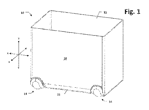
[0009] Figure 1 is a perspective view of an article movement system
including an
article supported for omni-directional rolling motion by a plurality of ball
wheels;
[0010] Figure 2 is a rear view of the article of Figure 1;
[0011] Figure 3 is an side view of the article of Figure 1, in vertical
orientation;
[0012] Figure 4 is a side view of the article of Figure 1, in an inclined
orientation;
[0013] Figure 5 is a side view of the article of Figure 1, in a
horizontal orientation;
[0014] Figure 6 is a perspective view of a representative one of the ball
wheels of
Figure 1;
[0015] Figure 7 is a side view of the ball wheel of Figure 6;
[0016] Figure 8 is a front view of the ball wheel of Figure 6;
[0017] Figure 9 is a bottom view of the ball wheel of Figure 6;
[0018] Figure 10 is a side view of another embodiment of a ball wheel;
[0019] Figure 11 is a bottom view of the ball wheel of Figure 10;
[0020] Figure 12 is a sectional view taken along line 12-12 of Figure 7;
[0021] Figure 13 is a sectional view taken along line 13-13 of Figure 8;
[0022] Figure 14 is a detail view of area 14 of Figure 13;
[0023] Figure 15 is a side view of a further embodiment of a ball wheel,
including
a plurality of micro-casters;
[0024] Figure 16 is a top view of the ball wheel of Figure 15;
[0025] Figure 17 is a sectional view taken along line 17-17 of Figure 16;
[0026] Figure 18 is a sectional view taken along line 18-18 of Figure 16;
[0027] Figure 19 is a sectional view taken along line 19-19 of Figure 16;
[0028] Figure 20 is an exploded perspective view of a representative one
of the
micro-casters of the ball wheel of Figure 15;
[0029] Figure 21 is another exploded perspective view of the micro-caster
of
Figure 20;
3
CA 03031755 2019-01-22
WO 2018/031648 PCT/US2017/046087
[0030] Figure 22 is a bottom view of the micro-caster of Figure 20;
[0031] Figure 23 is a sectional view taken along line 23-23 of Figure 22;
[0032] Figure 24 is a sectional view taken along line 24-24 of Figure 22;
[0033] Figure 25 is a detail view of area 25 of Figure 24;
[0034] Figure 26 is a perspective view of an upper section of a shell of
the ball
wheel of Figure 15;
[0035] Figure 27 is a perspective view of a lower section of the shell of
the ball
wheel of Figure 15;
[0036] Figure 28 is a sectional view of an additional embodiment of a
ball wheel,
taken along a line similar to that of Figure 13;
[0037] Figure 29 is a sectional view of the ball wheel of Figure 28,
taken along a
line similar to that of Figure 12;
[0038] Figure 30 is a sectional view of another embodiment of a ball
wheel, taken
along a line similar to that of Figure 13;
[0039] Figure 31 is a sectional view of a further embodiment of a ball
wheel,
taken along a line similar to that of Figure 18, including a tracker wheel;
[0040] Figure 32 is a bottom view of an upper section of the shell of the
ball
wheel of Figure 31;
[0041] Figure 33 is a detail view of area 33 of Figure 32;
[0042] Figure 34 is a side view of an article movement system, including
the ball
wheel of Figure 31 attached to an article in a vertical orientation;
[0043] Figure 35 is a side view of the article movement system of Figure
34,
including the ball wheel of Figure 31 attached to the article in an inclined
orientation;
[0044] Figure 36 is a perspective view of an additional embodiment of a
ball
wheel, including a suspension unit and a brake unit;
[0045] Figure 37 is a partially exploded perspective view of the ball
wheel of
Figure 36;
[0046] Figure 38 is a top view of the ball wheel of Figure 36;
[0047] Figure 39 is a sectional view taken along line 39-39 of Figure 37;
[0048] Figure 40 is a detail view of area 40 of Figure 39;
4
CA 03031755 2019-01-22
WO 2018/031648 PCT/US2017/046087
[0049] Figure 41 is an exploded view of the suspension unit of the ball
wheel of
Figure 36;
[0050] Figure 42 is an exploded view of the brake unit of the ball wheel
of Figure
36;
[0051] Figure 43 is a sectional view, taken along line 43-43 of Figure
42, of a
brake shoe and rod of the brake unit;
[0052] Figure 44 is a sectional view of an alternate embodiment of the
brake
shoe and rod of Figure 43, shown in position over a ball;
[0053] Figure 45 is a bottom view of the brake shoe of Figure 44;
[0054] Figure 46 is a perspective view of the ball wheel of Figure 36,
equipped
with a suspension replacement unit and a brake replacement unit in lieu of the
suspension unit and the brake unit;
[0055] Figure 47 is an exploded side view of the suspension replacement
unit
and the brake replacement unit of Figure 46; and
[0056] Figure 48 is sectional view of the ball wheel of Figure 36
incorporated into
an article movement system.
Detailed Description of Preferred Embodiments
[0057] Referring to Figures 1-3, according to an embodiment of the
present
invention, an article movement system 10 includes an article 12 and one or
more ball
wheels 14. The article 12 includes first and second article surfaces 16, 18
meeting at a
first article edge 22. The one or more ball wheels 14 are located at least
along the first
article edge 22 such that the article 12 is supported for omni-directional
rolling motion
over an underlying surface 24 with either of the first and second surfaces 16,
18
oriented generally parallel therewith, and at any orientation therebetween.
[0058] In the depicted embodiment, the first and second article surfaces
16, 18
are generally perpendicular. The article 12 additionally includes a third
article surface
26 generally opposite and parallel with the first article surface 16 and
generally
perpendicular with the second article surface 18. The second and third article
surfaces
18, 26 meet at a second article edge 30. Advantageously, one or more ball
wheels 14
are also located along the second article edge 30, supporting the article 12
for rolling
CA 03031755 2019-01-22
WO 2018/031648 PCT/US2017/046087
motion between the second and third article surfaces 18, 26 in the same manner
as the
one or more ball wheels 14 along the first article edge 22. Preferably, the
article 12
includes at least four ball wheels 14, with a ball wheel 14 located proximate
each end of
the first and second article edges 22, 30.
[0059] As used herein, the term "edge" refers generally to the zone along
which
adjacent surfaces of the article meet. An "edge" is not necessarily a "sharp"
edge, such
as a perpendicular junction between the surfaces. For instance, in the
depicted
embodiment, the first and second article edges 22 and 30 both traverse curves
between
their respective articles surfaces. The use of articles with curved edges
along which
ball wheels are mounted can be advantageous, as it allows the ball wheels to
recess
further into the article.
[0060] For efficiency of illustration, the article 12 is depicted as
generic, partially-
enclosed volume; it should be appreciated that the article movement system 10
is not
limited to this article, or to any particular type of article 12. Luggage
cases, crates,
carts, and dollies are some non-limiting examples of articles to which ball
wheels 14
could be advantageously mounted along one or more edges thereof. Likewise, the
article 12 could be completely or partially solid between surfaces thereof,
define a
permanently open or selectively closeable interior storage volume, or
incorporate one or
more open sides.
[0061] For the purposes of providing a common frame of reference, the
underlying surface 24 defines an x-z plane, with the y-direction being
perpendicular
thereto. The x-direction extends parallel with, and z-direction perpendicular
to the first
article edge 22. Thus, in Figures 1-3 the first and second article surfaces
16, 18 lie in x-
y and x-z planes, respectively. In Figure 4, the article 12 has rotated about
an x-axis
(though not necessarily the x-axis along which the first article edge 22
extends) with
neither of the first and second article surfaces 16, 18 lying in x-y or x-z
planes. In
Figure 5, the article 12 is now oriented with the first and second articles
surfaces 16, 18
in x-z and x-y planes, respectively. Naturally, the article movement system 10
is not
restricted to movement in these orientations. Also for reference purposes, the
article 12
orientation in Figures 1-3 will be called vertical, the article 12 orientation
in Figure 5 will
6
CA 03031755 2019-01-22
WO 2018/031648 PCT/US2017/046087
called horizontal, and any intermediate orientation rotated about an x-axis
between
vertical and horizontal (including that of Figure 4) will be called inclined.
[0062] Multiple embodiments of components of the invention will be
described
herein. Similar reference numerals will be used to label similar elements,
with a
terminal letter (e.g., 14, 14A, 14B... 14X) used for different embodiments.
Except as
specified herein, similarly labeled elements should be understood as
functioning in
essentially the same manner.
[0063] Referring also to Figures 6-9, each ball wheel 14 includes a shell
32 and
ball 34. The shell 32 defines a ball opening 36 through which a portion of the
ball 34
extends. A bearing arrangement 40 supports the ball 34 for motion relative to
the shell
32. The bearing arrangement 40 is depicted generically in Figures 7 and 8;
specific
embodiments of bearing arrangements will be described in greater detail below.
[0064] The shell 32 is fixed to the article 12 and is advantageously
completely
detachable therefrom, such that each ball wheel 14 can be formed separately
from the
article 12 and later affixed thereto. Alternately, some or all of the shell 32
can be
formed integrally with adjacent portions of the article 12. Parts also
offering different
functions, such as a brake and suspension mechanisms (described in greater
detail
below), can cooperatively form portions of the shell 32.
[0065] The overall shape of shell 32 can vary; for example, based on the
physical
configuration of the specific bearing arrangement 40 contained therein.
However, the
shell 32 is generally physically configured so as to retain the ball 34 and
bearing
arrangement 40 therein, while allowing enough the ball 34 to extend through
the ball
opening 36 to remain continuously in contact with the underlying surface 24
with the
article 12 in vertical, horizontal and inclined orientations, and when
transitioning
therebetween.
[0066] Allowing this contact means, in part, that the shell 32, ball 34,
ball opening
36 and bearing arrangement 40 should be dimensioned such that at least a 90
degree
arc of the ball 34 about an x-axis will protrude past the respective article
edge 22, 30. In
other words, the ball 34 is able to contact two orthogonal planes
simultaneously without
interference from the shell 32 or the surfaces of the article 12 (in Figure 7,
those would
be x-z and x-y planes). In the depicted embodiment, the respective article 12
surfaces
7
CA 03031755 2019-01-22
WO 2018/031648 PCT/US2017/046087
adjacent the edges 22, 30 are substantially flat. Where the respective article
12
surfaces adjacent the edges on which ball wheels are to be utilized are not
flat (e.g., a
suitcase where one or more sides bows outwardly), the ball 34 should extend
past the
intersection of perpendicular planes tangent to outermost points of the
adjacent article
surfaces (which is also the case in the depicted embodiment, except that there
is not a
single outermost point due to the flatness of the surfaces 16, 18, 26).
[0067] Theoretically, referring to Figures 10 and 11, a circular ball
opening 36X
could permit necessary arc of ball 34X to protrude therethrough without
interference.
However, the circular ball opening 36X presents a number of practical
shortcomings. If
too close to an equator of the ball 34X, the ball 34X risks simply falling out
of the shell
32X anytime the ball wheel 14X is moved out of contact with the underlying
surface
24X. Additionally, the dynamic forces acting on the ball 34X when an
associated article
is being pulled over the underlying surface 24X may similarly urge the ball
34X out the
shell 32X, as could the force exerted on the ball 34X by a brake mechanism or
the like.
[0068] Another practical problem is that engagement between the ball 34X
and a
peripheral lip 42X of the ball opening 36X will inhibit rotational motion,
particularly rapid
rotational motion. The geometry of the shell 32X must allow space for a
bearing
arrangement 40X to function to support the ball 34X proximate to the lip 42X.
If the
shell 32X is made large enough to do this around the circular opening 36X, it
would
likely extend into the planes of contact with the ball 34X in the horizontal
and vertical
orientations of the respective article.
[0069] By way of illustration, if an article attached to the ball wheel
14X is (in the
depicted orientation) being pulled in the direction represented by arrow 44X,
the ball
34X needs to rotate as indicated by arrow 46X. Since the ball 34X is not
pinned in
place by an axle, the ball 34X will tend to be urged against the lip 42X in
area 50X ¨
where the highest surface velocities on the ball 34X will be encountered. Any
bearing
arrangement must be able to engage the ball 34X sufficiently well proximate
the area
50X to prevent contact with the lip 42X.
[0070] Consequently, referring back to Figures 6-9, a non-circular ball
opening 36
is preferred. The ball opening 36 does not lie in a single plane, but rather
constitutes a
three-dimensional curved opening having major and minor angular extents 50,
52. The
8
CA 03031755 2019-01-22
WO 2018/031648 PCT/US2017/046087
major angular extent 50 is sufficient to allow the ball 34 contact two
orthogonal planes
simultaneously without interference from the shell 32 ¨ which, with the ball
wheel 14
mounted on an edge of the article 12 (e.g., the first edge 22) allows the ball
34 to
remain in contact with the underlying surface 24 in vertical, horizontal and
inclined
orientations of the article 12. In other words, the major angular extent 50 of
the ball
opening 36 must allow at least a 90 degree arc of the ball 34 to extend past
the shell 32
around the first edge 22 (or second edge 30) without interference.
[0071] Using the reference frame previously established, the article
edges 22, 30
extend along x-axes. Referring also to Figures 12 and 13, the major angular
extent 50
of the ball opening 36 will form an arc (although not necessarily a circular
arc) extending
partially around a x-axis 54 of the ball 34 parallel with the edges 22, 30.
The minor
angular extent 52 of the ball opening 36 will form a shorter arc (again, not
necessarily a
circular arc) extending partially around a z-axis 56 of the ball 34. The major
angular
extent 50 is preferably greater than approximately 90 degrees about the x-axis
54, and
more preferably between approximately 120 degrees to approximately 200
degrees.
The minor angular extent 52 is preferably less than approximately 160 degrees
about
the z-axis 56, and more preferably between approximately 60 degrees to
approximately
135 degrees. This non-circular ball opening 36 advantageously enhances ball 34
retention with the minor angular extent 52 ensuring that the ball 34 cannot be
urged out
of the shell 32, while major angular extent 50 permits the necessary degree of
ball 34
contact to offer rolling support to an article 12 in vertical, horizontal and
inclined
orientations.
[0072] A peripheral lip 42 forms the perimeter of the ball opening 36,
advantageously extending contiguously therearound. The geometry of the lip 42
is best
appreciated in the sectional views of Figures 12 and 13 and the detail view of
Figure 14.
In the depicted embodiment, the lip 42 tapers from a curved shoulder 60
forming its
inner edge to a point 62 forming its outer edge, with "inner' and "outer"
being used with
reference to the edge of the lip 42 where the inside of the shell 32, the ball
34 and the
bearing arrangement 40 converge and the edge of the lip 42 where the outside
of the
shell 32 converges with the ball 34, respectively. Additionally, the inner
face 64 of the
peripheral lip is advantageously angled such that a spacing 66 between the
ball 34 and
9
CA 03031755 2019-01-22
WO 2018/031648 PCT/US2017/046087
the shoulder 60 is greater than a spacing 68 between the ball 34 and the point
62. An
outer portion 70 of the inner face 64, inwardly of the point 62, also has the
same radius
of curvature as the ball 34.
[0073] The shoulder 60 configuration and spacing 66 are set such that any
freely
moving components of the bearing arrangement 40 (e.g., individual ball
bearings) are
retained between the ball 34 and the shell 32. Additionally, where the ball
wheel 14 is
equipped with a brake mechanism (as will be described below), the inner face
64 of the
lip 42, and more particularly the outer portion 70 thereof, can provide an
engagement
surface to enhance braking force.
[0074] The overall geometry and configuration of the lip 42 also help
prevent
fouling of the bearing arrangement 40 with debris picked up by the ball 34
when the
article 12 is pulled over the underlying surface 24. To illustrate this
function, referring
particularly to Figure 13, when the article is pulled in direction 44, the
ball 34 will rotate
in direction 46. With reference to direction 44, the edge of the lip 42 to the
left side of
Figure 13 is the leading edge 72 and the edge of the lip 42 to the right side
of Figure 13
is the trailing edge 74. The forces acting on the ball 34 will tend to urge it
closer to the
trailing edge 74 and further away from the leading edge 72 (primarily due to
the taking
up of tolerances and any compressibility of the ball 34). The resultant
smaller gap
between the ball 34 and the trailing edge 74 will facilitate the ability of
the point 62 to act
as a "wiper" at the trailing edge. While not actually contacting the ball 34
(as the
bearing arrangement 40 precludes such contact), the point 62 at the trailing
edge 74 will
be better positioned to engage debris carried on the rotating ball 34 and
remove the
debris before it is introduced into the bearing arrangement 40. On the leading
edge 72,
the resultant larger gap, aided by the funnel effect of spacing 66 being
larger than
spacing 68, will help funnel any previously introduced debris out of the
bearing
arrangement 40. This same general effect would be reproduced in any direction
of
article 12 motion.
[0075] To further assist in preventing debris from entering the bearing
arrangement 40, the lip 42 can be magnetized. Consequently, ferromagnetic
and/or
otherwise charged debris particles will be attracted to the lip 42 prior to
entering. A
CA 03031755 2019-01-22
WO 2018/031648 PCT/US2017/046087
magnetized lip 42 can also offer other benefits in connection with specific
bearing
arrangement 40 embodiments, as will be discussed in greater detail below.
[0076] Referring to Figures 12 and 13, the shell 32 is advantageously
formed in
multiple parts to facilitate manufacture and assembly of the ball wheel 14.
For example,
with reference to the Figure 12 orientation, the shell 32 includes upper and
lower shell
sections 80, 82. Preferably the sections 80, 82 are secured together by
releasable
fasteners 84, such as screws or the like. The upper section 80 advantageously
includes
a neck 86 which facilitates attachment of the ball wheel 14 to the article 12.
The
peripheral lip 42 is formed in the lower section. The ball 34 and all or a
portion of the
bearing arrangement 40 can be placed in the lower section 82, with the upper
section
80 then being connected to secure the ball and bearing arrangement 40 in place
within
the shell 32. In certain embodiments, the neck 86 can be configured to
facilitate the
installation of a remainder of the bearing arrangement 40, as well as various
accessories (explained in greater detail below), once the sections 80, 82 are
connected.
[0077] The bearing arrangement 40 can be made in a variety of
configurations to
achieve the operational objectives of the ball wheel 14 in connection with its
rolling
support of the article 12. In a particularly advantageous embodiment,
referring to
Figures 15-19, the bearing arrangement of a ball wheel 14A includes a
plurality of
micro-casters 90A engaging the ball 34A from within the shell 32A. The micro-
casters
90A are closely fitted into caster seats 92A formed in the shell 32A. The
micro-casters
90A are rotatable relative to their seats 92A to support the ball 34A for
omnidirectional
rolling motion in the vertical, horizontal, and inclined orientations of an
attached article
(e.g., the article 12).
[0078] For additional rolling support of the ball 34A, a plurality of
ball bearings
94A can also be arranged between the ball 34A and the shell 32A, being free to
circulate through a volume 96A therebetween, the radial width of the volume
96A
between the ball 34A and the shell 32A being slightly greater than the
diameter of the
bearings 94A. As explained in greater detail below, the micro-casters 90A are
preferably configured such that the ball bearings 94A are free to travel over
most of the
ball-facing surface of each micro-caster 90A.
11
CA 03031755 2019-01-22
WO 2018/031648 PCT/US2017/046087
[0079] The volume 96A is preferably a partial sphere, terminating at the
lip 42A.
The curvature of the spherical volume 96A preferably matches that of the ball
34A.
Preferably, the micro-casters 90A are arranged to approximately center the
ball 34A
within the volume 96A under load (through vertical, horizontal and
intermediate
orientations of an article 12), while also maintaining a predetermined spacing
from the
lip 42A. As described above in connection with Figures 13 and 14, this spacing
will vary
during rolling motion, and the geometry of the lip 42A is preferably as
described therein.
The bearings 94A help ensure this spacing is maintained, even during very
extreme
motion. By employing a magnetized lip 42A and ferromagnetic bearings 94A, the
presence of sufficient bearings 94A in the vicinity of the lip 42 can also be
facilitated.
[0080] Preferably four micro-casters 90A are included, spaced
symmetrically in
quadrants around an upper section 80A of the shell 32A, as can best be seen in
Figure
16. Additionally, a central axis of each micro-caster 90A is offset by an
angle 98A (see
Figure 17) of approximately 45 ¨ 90 degrees from a central axis of the neck
86A, and
most preferably between approximately 60-70 degrees. Advantageously, the micro-
caster 90A locations do not coincide with the maximum and minimum angular
extents
50A, 52A of the ball opening 36A. Instead, one micro-caster 90A is located in
each
quadrant between the y-z and y-x planes containing the maximum and minimum
angular extents 50A, 52A.
[0081] Referring to Figures 20-24, each micro-caster 90A includes an
inner
housing 100A in which a caster wheel 102A is rotatably mounted about an axle
104A,
and outer housing 106A. Advantageously, the caster wheel 102A can be formed as
a
sealed, deep groove bearing. The outer housing 106A is fixedly mounted into a
respective caster seat 92A. The inner housing 100A is mounted within the outer
housing 106A so as to be freely rotatable relative to the outer housing 106A
and seat
92A. Advantageously, the inner housing 100A is rotatably supported relative to
the
outer housing 106A via a plurality of ball bearings 108A riding between tracks
110A,
111A formed in an upper surface (relative to the Figure 23 and 24 orientation)
of the
inner housing 100A and a lower surface of the outer housing 106A,
respectively.
[0082] The axle 104A is mounted eccentrically within the inner housing
100A,
such that the rotational axis of the inner housing 100A extends at a right
angle to, but
12
CA 03031755 2019-01-22
WO 2018/031648 PCT/US2017/046087
does not intersect, the rotational axis of the axle 104A. Thus, the rotational
axis of the
axle 104A is parallel with a plane tangent to the lower (relative to the
Figure 23 and 24
orientation) peripheral edge of the micro-caster 90A, while the rotational
axis of the
inner housing 100A is perpendicular to such a plane.
[0083] As noted above, one micro-caster 90A is advantageously located in
each
quadrant formed between the maximum and minimum angular extents 50A, 52A (as
best appreciated in Figure 16) and at an angle 98A from a central axis of the
neck 86A.
Preferably, the location of the micro-casters 90A within the quadrants is
selected such
that, if the ball 34A were divided into leading and trailing hemispheres
during rolling
motion throughout the vertical, horizontal and inclined orientations of an
article 12, two
of the contact points between the ball 34A and caster wheels 102A will be in
the leading
hemisphere and two will be in the trailing hemisphere ¨ except for an
exceptional case.
In the exceptional case, an article 12 is being pulled in a direction of
motion that aligns
two opposing ball wheels (e.g., if an article were being pulled in the
direction of the
sectional line 17-17 in Figure 16). In this case, the aligned micro-casters
90A are
centered and in the leading and trailing hemispheres, respectively, and the
other two
micro-casters 90A are essentially located along the division between the
leading and
trailing hemispheres. To achieve this, each of the micro-casters 90A is
preferably within
+/-30 degrees of the plane bisecting its quadrant (in Figure 16, sectional
line 17 lies in
such a plane), and more preferably, within +/- 5 degrees. The phrase
"positioned for
dual engagement" is herein defined to refer to the positioning of micro-
casters 90A as
described in this paragraph.
[0084] It should be noted that the sectional view of Figure 23 is taken
along the
line of the rotational axis of the axle 104A, and not through the center of
the micro-
caster 90A. Figure 24 is a true cross-section, taken perpendicular to the
Figure 23
section along a line intersecting the rotational axis of the inner housing
100A.
Preferably, the inner housing 100A is closed by a cap 112A. The cap 112A
defines a
caster wheel opening 114A through which enough of the caster wheel 102A
extends to
engage the ball 34A. The cap 112A is fixed to, and rotates with, the inner
housing
100A. An outer surface 116A (i.e., facing away from the inner housing 100A) of
the cap
112A is contoured to continue the curvature of the inner surface of the shell
32A (which
13
CA 03031755 2019-01-22
WO 2018/031648 PCT/US2017/046087
partially defines the volume 96A), except for a central protrusion 118A
extending around
the caster wheel opening 114A. Thus, the cap 112A allows any free bearings 94A
to
travel smoothly across the micro-caster 90A, while the central protrusion 118A
diverts
any free bearings around the caster wheel 102A. The cap 112A also helps
prevent the
entrance of any debris into the inner housing 100A which might inhibit
rotation of the
caster wheel 102A about its axle 104A, as does the protrusion 118A ¨ which is
also
effective to deflect and remove debris from the caster wheel 102A.
[0085] The central protrusion 118A can also help transfer impact loads
from the
caster wheel 102A to the shell 32A. The compressibility of the ball 34A by the
caster
wheel 102A can result in the ball 34A also coming into contact with the
central
protrusion 118A under impact loads above a certain threshold. That threshold
can be
varied by adjusting the amount of the wheel 102A that clears the central
protrusion
118A.
[0086] The volume between the inner and outer housings 100A, 106A is
preferably enclosed by a sealing ring 120A. The sealing ring 120A prevents the
introduction of any debris between the inner and outer housings 100A, 106A,
preventing
fouling of the bearings 108A. Like the cap 112A with its contoured outer
surface 116A,
the sealing ring 120A advantageously has an outer surface 122A contoured to
continue
the curvature of the inner volume 96A of the shell 32A. Thus, around the
central
protrusion 118A, the entire outer surface of the micro-caster 90A is composed
of the
outer surfaces 116A, 122A and does not interrupt the preferably spherical
curvature of
the volume 96A. As best seen in Figure 25, a narrow, step-shaped gap 124A
separates
the cap 112A and the sealing ring 120A, such that free rotation of the inner
housing
100A and cap 112A is not inhibited by the sealing ring 120A.
[0087] Referring to Figures 26 and 27, the shell 32A of the ball wheel
14A also is
preferably formed with separate, connectable upper and lower sections 80A,
82A. The
upper section 80A includes the neck 86A and the caster seats 92A. The ball
opening
36A is defined in the lower section 82A surrounded by the peripheral lip 42A,
as are
notches 126A dimensioned to closely accommodate the caster seats 92A. This
arrangement easily allows the micro-casters 90A to be mounted in their seats
92A, any
bearings 94A to be introduced and the ball 34A to be put in place. The lower
section
14
CA 03031755 2019-01-22
WO 2018/031648 PCT/US2017/046087
82A can then be attached (preferably by fasteners 84A ¨ see Figure 19),
securing the
entire bearing arrangement and the ball 34A in place.
[0088] In another embodiment, referring to Figures 28 and 29, a ball
wheel 14B
utilizes a bearing arrangement including a plurality of ball bearings 94B
which freely
circulate through a bearing volume 96B formed between the ball 34B and the
shell 32B,
the volume 96B preferably forming a partial sphere with the same curvature as
the ball
34B. The circulating ball bearings 94B support the ball 34B for omni-
directional rolling
motion in the vertical, horizontal, and inclined orientations of an attached
article (e.g.,
the article 12). Only a portion of the ball bearings 94B are shown for clarity
of
illustration; nonetheless, it is preferred that the number of ball bearings
94B not result in
the volume 96B being tightly packed with ball bearings, as this could inhibit
free
circulation. At the same time, the number should be sufficient to ensure at
least some
ball bearings will be adequately positioned to offer support throughout the
desired range
of article orientations.
[0089] Advantageously, the geometry of the bearing volume 96B within the
non-
circular opening 36B results in the highest concentration of ball bearings 94B
being
proximate to the x-axis 54B about which the ball 34B rotates during rolling
motion in the
z-direction. Conversely, less ball bearings 94B will be contacting the ball
34B proximate
the rotational "equator" (lying in the y-z plane dividing the ball 34B into
hemispheres).
Proximate the x-axis 54B, the surface velocities of the ball 34B will be
lower, while
surface velocities will be highest near the y-z equator. Therefore, the
rotational drag is
reduced, and the ball wheel 34B enjoys higher speed and load limitations.
[0090] As with the ball wheels 14, 14A, the shell 32B of the ball wheel is
advantageously formed with upper and lower sections 80B, 82B, with the upper
section
80B carrying the neck 86B and the lower section 82B defining the ball opening
36B with
the peripheral lip 42B. As described above, the use of separate sections
facilitates
assembly of the ball wheel 14B. Due to the large number of ball bearings 94B
it may
also be desirable for a sealable passage 126B to be formed extending axially
though
the neck 86B to the bearing volume 96B. The diameter of the passage 126B
should be
sufficient to allow the ball bearings 94B to pass therethrough. It may not be
practical to
contain the desired number of ball bearings 94B between the upper and lower
sections
CA 03031755 2019-01-22
WO 2018/031648 PCT/US2017/046087
80B, 82B during connection thereof. A final number of the ball bearings 94B
could then
be introduced through the passage 126B after the shell 32B was connected
around the
ball wheel 34B.
[0091] As noted above, in a ball wheel with a bearing arrangement like
that of the
ball wheel 14B, there is a preferred balance to be achieved between too many
ball
bearings, resulting in undesirable binding, and too few ball bearings,
resulting in
insufficient support. In a ball wheel 14C (see Figure 30), the bearing
arrangement again
includes a plurality of ball bearings 94C freely circulating in a bearing
volume 96C
defined between the shell 32C and the ball 34C. However, peripheral edges of
the
bearing volume 96C communicate with a bearing well 130C defined in the shell
32C
away from the ball 34C. Thus, filling the bearing volume 96C with ball
bearings 94C
does not present a potential binding problem, as excess bearings 94C can
freely
circulate into and out of the bearing well 130C as necessary.
[0092] As will be appreciated from the foregoing, the present invention
offers
multiple embodiments of bearing arrangements 40 for ball wheels 14 that will
support
the article 12 for omni-directional rolling motion in vertical, horizontal,
and inclined
orientations. However, when pulling an article 12 over a distance (which is
most likely
to occur in the inclined or horizontal orientations), is can be desirable to
ensure that the
article 12 will track in an essentially straight line. Some degree of
beneficial tracking is
already provided by the specific bearing arrangements described above in
connection
with the ball wheels 14A, 14B and 14C. For example, the alignment of the micro-
casters 90A when pulling an article in the inclined orientation will tend to
favor continued
straight-line motion. Similarly, the circulation pattern established by the
ball bearings
94B (or 94C) when pulling an article in the inclined orientation will tend to
favor
continued straight-line motion.
[0093] Nonetheless, in a further embodiment, referring to Figures 31-33,
a ball
wheel 14D incorporates a tracker wheel 132D rotatably mounted in a tracker
recess
134D in the shell 32D and extending toward the ball 34D. Preferably,
tolerances are
such that, absent any force urging the ball 34D toward the tracker wheel 132D
(e.g., the
weight of an article 12D supported by the ball wheel 14D when inclined or
horizontal),
there is a slight gap between the ball 34D and the tracker wheel 132D.
16
CA 03031755 2019-01-22
WO 2018/031648 PCT/US2017/046087
Advantageously, the tracker wheel 132D can be formed as a sealed, deep groove
bearing, like the caster wheel 102A. The tracker wheel 132D is mounted with a
fixed
axis of rotation about an axle 136D, or other rotational mounting mechanism.
The axle
136D is a x-axis generally parallel with the axis 54D about which the maximum
angular
extent 50D of the ball opening 36D extends.
[0094] Advantageously, the tracker wheel 132D is surrounded by a
protrusion
138D surrounding the periphery of the recess 134D, which, like the central
protrusion
118A, diverts any free bearings (like the bearings 94A, 94B, 94C) ¨ and
deflects any
debris ¨ therearound. In the depicted embodiment, the ball wheel 14D uses
micro-
casters 90D as bearing arrangement and the tracker whee1132D is preferably
positioned intermediate two of the micro-casters 90D and their seats 92D.
However, it
will be appreciated that a tracker wheel could be advantageously employed with
other
bearing arrangements, including any of the disclosed bearing arrangements.
[0095] Referring to Figure 34, the tracker wheel 132D is positioned so
that its
axle 136D (and hence the rotational axis thereof) is on a level with the x-
axis 54D
passing through the center of the ball 34D with the article 12D in the
vertical orientation.
In other words, the tracker wheel 132D is essentially to the side of the ball
34D. Gravity
and the weight of the article 12D therefore do not urge the ball 34D into
engagement
with the tracker wheel 132D in the vertical orientation, such that the tracker
wheel 132D
essentially does not impact the movement of the ball 34D relative to the
bearing
arrangement 40D and the shell 32D.
[0096] Referring to Figure 35, with the article 12D moved into an
inclined
orientation, the axle 136D of the tracker wheel 132D moves above the x-axis
54Dof the
ball 34D. Now gravity, the weight of the article 12D and the forces acting on
the ball
34D as the article 12D is pulled in direction of arrow 140D all act to engage
the tracker
wheel 132D with the ball 34D. Frictional engagement with the tracker wheel
132D,
which can only rotate about its axle 136D, now helps constrain the ball 34D in
rotation
about its x-axis 54D. Consequently, the straight line tracking of the article
12D when
pulled in an inclined or horizontal orientation is enhanced. This is even the
case when
the article 12D is being pulled over a surface with a slope offset to either
side of the
desired direction of motion.
17
CA 03031755 2019-01-22
WO 2018/031648 PCT/US2017/046087
[0097] As discussed above, various additional functional components can be
integrated into the ball wheel 14. For example, referring to Figures 36-39, a
ball wheel
14E includes a suspension unit 146E and a brake unit 150E. The suspension unit
146E
mounts between the neck 86E of the ball wheel 14E and the article 12E and
absorbs
bumps and shocks experienced by the ball wheel 14E as it passes over the
underlying
surface, thereby offering a smoother ride and reducing the likelihood of
damage to
components of the article 12E, ball wheel 14E or the associated structure. The
brake
unit 150E is mounted in an internal passage 152E extending axially through the
neck
86E and is effective to apply a braking force to the ball 34E to slow or cease
rotational
movement thereof relative to the shell 32E.
[0098] The suspension unit 146E, referring more particularly to Figures 40
and
41, includes upper and lower sections 156E, 160E that are slidable relative to
each
other, with the lower section 160E being seated on the shell 32E around the
neck 86E.
To regulate the relative motion of the upper and lower sections 156E, 160E, a
compression spring 162E extends therebetween, and can be brazed, or otherwise
connected, to the upper section 156E at the top and to the lower section 160E
at the
bottom. A retention ring 164E at the top of the spring 162E further enhances
fit and
connection.
[0099] For ease of assembly, the lower section 160E includes a lower
spring seat
166E and an outer cover 170E. Likewise, the upper section 156E includes an
upper
spring seat 172E and an outer cover 174E. To facilitate smooth relative
movement, a
lubricant can be applied between the adjacent surfaces of the lower and upper
spring
seats 166E, 172E. The outer covers 170E, 174E can be attached after assembly
of the
spring seats 166E, 172E and the spring 162E, by brazing or other connection
means.
[00100] Concentric bores 176E, 180E are defined through the spring seats
166E,
172E respectively to facilitate securing the ball wheel 14E to the article
12E, and for
allowing retraction of the ball wheel 14E further within the article 12E, as
will be
explained further below. A cushioned dampener 184E, also with a concentric
bore
186E, is arrayed between the spring seats 166E, 172E to prevent sharp impacts
therebetween.
18
CA 03031755 2019-01-22
WO 2018/031648 PCT/US2017/046087
[00101] The brake unit 150E, referring more particularly to Figures 40, 42
and 43,
is located in the internal passage 152E located within the neck 86E of the
ball wheel
14E. The brake unit 150E includes a brake housing 190E from which a brake shoe
192E is extendable toward the ball 34E. The brake shoe 192E is connected via a
brake
rod 194E to a brake piston 196E. A cam operator 200E is operable via a brake
cable
202E to urge the brake shoe 192E, via the rod 194E and piston 196E, toward the
ball
34E. A tension spring 204E acts to retract the brake shoe 192E automatically
when
braking force is not applied via the cam operator 200E. Design tolerances are
preferably such that, even with the spring 204E fully compressed, the brake
shoe 192E
will not completely exit the internal passage 152E ¨ further ensuring proper
brake shoe
192E alignment.
[00102] The brake housing 190E includes opposed slots 206E to allow a full
range
of motion of the cam operator 200E and an exit path for the brake cable 202E.
A cam
mounting sleeve 210E is received within the brake housing 190E having slots
212E
aligned with the slots 206E. The cam mounting sleeve 210E mounts a cam axle
214E
via axle notches 216E. The cable 202E is attached to an opposite end of the
cam
operator 200E via a cable axle 220E and bushing 222E.
[00103] When assembled, the brake unit 150E can simply be "plugged" into
the
internal passage 152E or removed with relative ease. A shoulder 224E on the
housing
190E limits insertion to the proper distance via engagement with a
corresponding
constriction 226E in the internal passage 152E. A threaded plug 230E is
threaded into
the internal passage 152E, closing the neck 86E and holding the brake unit
150E in
place. The plug 230E has an internal bore 232E. Hex surfaces or the like are
formed
on an upper portion of the bore 232E to facilitate insertion and removal of
the plug
230E, while a lower portion of the bore 232E is threaded to facilitate
connection of the
ball wheel 14E to the article 12E (as described below).
[00104] When braking force is applied, the shoe 192E extends and applies
braking
force on the ball 34E by directly engaging the ball 34E. To improve
engagement, a
lower face 234E of the brake shoe 192E is contoured to match the curvature of
the ball
34E. A peripheral edge 236E of the brake shoe 192E is advantageously curved to
direct bearings 94E (and any debris) therearound. (A hex opening 240E extends
into
19
CA 03031755 2019-01-22
WO 2018/031648 PCT/US2017/046087
the lower face 234E to facilitate threading the shoe 192E/rod 194E into the
cap 196E.)
The ball wheel 14E can be configured such that the braking force exerted by
the shoe
192E urges the ball 34E into contact with the peripheral lip 42E, further
enhancing the
effective braking action.
[00105] The clearance between the lower surface 234E of the shoe 192E and
the
ball 34E is preferably relatively small, which allows for quicker braking
action with less
shoe travel 192E and also minimizes fouling problems that might be engendered
by a
larger clearance. With a small clearance, high impact forces (e.g., when a
heavily laden
article 12E is rolled off a high curb) might cause sufficient relative
movement between
the brake shoe 192E and the ball 34E to result in unwanted braking action. In
an
alternate embodiment (see Figures 44 and 45), the brake shoe 192F has a
plurality of
bearings 242F embedded in lower face 234F via low friction seats 244F. The
seats
244F are located within openings 246F extending into the face 234F (a
hexagonal seat
can be located within the hex opening 240F. The bearings 242F reduce the
incidence
and/or severity of unwanted braking action in high impact force scenarios.
[00106] Referring again to Figures 36 and 40, routing of the brake cable
202E out
of the ball wheel 14E is facilitated by aligned cable openings 250E formed in
the
suspension unit 146E and the neck 86E of the shell 32E. The openings 250E in
the
suspension unit 146E include aligned openings in both the lower spring seat
166E and
outer cover 170E of the lower section 160E. A cable notch 252E formed in the
outer
cover 174E of the upper section 156E ensures that compression of the
suspension unit
146E will not interfere with the brake cable 202E.
[00107] The modular design of the suspension unit 146E and brake unit 150E
allow for easy upgrading, and "plug and play" usability of such units. For
instance,
referring to Figures 46 and 47, a more basic configuration of the ball wheel
14E is
achieved by replacing the suspension unit 146E with a suspension replacement
unit
260E and replacing the brake unit 150E with a brake replacement unit 262E. The
replacement unit 260E fits over the neck 86E just like the suspension unit
146E, but
lacks the internal suspension components. A concentric bore 264E is formed
through
the replacement unit 260E like the opening 176E, to allow attachment to the
article 12
(explained below). Preferably, a cable opening 266E is formed through a side
of the
CA 03031755 2019-01-22
WO 2018/031648 PCT/US2017/046087
suspension replacement unit 260E, further enabling a ball wheel 14E
configuration
where a brake unit 150E is used without a suspension unit 146E.
[00108] Likewise, the brake replacement unit 262E is a unitary piece
lacking
braking components that seats in the internal passage 152E via a shoulder 270E
and is
secured in place by the threaded plug 230E just like the brake unit 150E. It
will be
appreciated that in yet another ball wheel 14E configuration, the brake
replacement unit
262E could also be used with a suspension unit 146E.
[00109] Referring to Figure 48, a socket 272E is formed along the edge 22E
(30E)
of the article 12E (preferably proximate the ends thereof ¨ see, e.g., Figures
1 and 2)
into which the neck 86E of the ball wheel 14E is received, along with attached
suspension unit 146E (or suspension replacement unit 260E). A connecting bolt
274E
is inserted from the interior of the article 12E through an opening 276E (and
preferably
also a washer 280E), and threaded into the plug 230E to secure the ball wheel
14E into
the socket 272E. As the head of the connecting bolt 274E (and washer 280E)
cannot
pass through the opening 276E, the connecting bolt 274E also effectively
delimits the
maximum extension of the suspension unit 146E, when the ball wheel 14E is so
equipped.
[00110] A retraction cable 282E is preferably routed through the interior
of the
article 12E along with the brake cable 202E. The retraction cable 282E allows
the ball
wheel 14E to be further retracted within the article 12E by compressing the
suspension
unit 146E via the cable 282E. Thus, the article 12E can require even less
space when
stowed. The routing of the brake and retraction cables 202E, 282E is depicted
schematically. It will be appreciated that similar cables from each of the
ball wheels
14E attached to the article 12E could be routed together to allow remote
operation of all
brake units 150E, and/or retraction of ball wheels 14E, simultaneously from a
single
point elsewhere on the article 12 (e.g., on a handle thereof).
[00111] To ensure proper alignment of the ball wheel 14E relative to the
article
12E, indexing surfaces 284E, 286E are formed on the exterior of the suspension
unit
146E (and suspension replacement unit 260E) and the interior of the socket
272E,
respectively. To ensure proper alignment of the suspension unit 146E (and
suspension
replacement unit 260E) over the neck 86E, respective indexing surfaces 290E,
292E
21
CA 03031755 2019-01-22
WO 2018/031648 PCT/US2017/046087
are also formed thereon. To ensure proper alignment of the upper and lower
sections
80E, 82E (as well as suspension and suspension replacement units 146E, 260E),
indexing marks 294E are formed thereon (see Figures 36 and 46). With all
components
indexed properly, the non-circular ball wheel opening 36E (and tracker wheel
132E) will
be properly oriented relative to the article 12E when the ball wheel 14E is
connected
thereto.
[00112] In an exemplary implementation of the article movement system 10,
the
article 12E is sold with ball wheels 14E with the suspension replacement unit
260E and
the brake replacement unit 262E. A user could later opt to upgrade to the
suspension
unit 146E and/or the brake unit 150E, and simply remove the ball wheels 14E
from the
article 12E by removing their respective connecting bolts 274E. With the ball
wheels
14E detached, the suspension replacement unit 260E would be taken off, the
threaded
plug 230E removed, and the brake replacement unit 262E pulled out. The brake
unit
150E would be installed, the threaded plug 230E replaced, the suspension unit
146E
placed over the neck 86E, and each ball wheel 14E reattached via its
connecting bolt
274E. Similarly, repair or replacement of damaged components is greatly
facilitated.
[00113] The foregoing embodiments are provided for exemplary and
illustrative
purposes; the present invention is not necessarily limited thereto. For
example, the
features of the above-described embodiments are described separately for
clarity of
illustration; however, features of different embodiments are readily
combinable. For
instance, any of the ball wheels 14-14E can be used in the system 10 with the
article
12. Likewise, the suspension and brake units 146E, 150E (as well as respective
replacement units 260E, 262E) of the ball wheel 14E could be integrated into
any of the
ball wheels 14-14D; the tracker wheel 132D-132E of the ball wheels 14D- 14E
could be
integrated into any of the other ball wheels 14-14C; and so on.
[00114] Different numbers of ball wheels 14-14E could be used on an
article 12
than shown. For example, more or fewer ball wheels 14 could be placed along
edges
22, 30. Ball wheels 14 could be placed on other edges, such as top edges of an
article
12. Ball wheels 14 could be placed on fewer edges; e.g., only along a single
edge, with
a more basic rolling support on other edges. Differently configured ball
wheels 14 could
be used on different edges. For instance, ball wheels 14 on edge 22 could be
equipped
22
CA 03031755 2019-01-22
WO 2018/031648 PCT/US2017/046087
with brake and suspension units, while ball wheels 14 on edge 30 could be
equipped
with replacement units. An article 12 could be configured to receive the neck
86 of a
ball wheel 14 directly without an intervening suspension or replacement unit.
[00115] Additionally, any suitable construction materials can be employed
for the
ball wheels; the present invention is not necessarily limited with respect
thereto.
Stainless steel, titanium, carbon fiber reinforced polymers and high strength
plastics are
advantageous for the ball wheels and housings. To minimize noise while
rolling, as well
as the generation of static electricity, balls in the ball wheels are
preferably coated with
a polyurethane or similar shell and may have a hard plastic core, or be a
solid ball.
[00116] As used in the context of the claims, ball wheels are
"substantially
identical" if they include all of the same elements recited in the claim in
which they are
both/all recited ¨ including elements recited directly in such claim, as well
as elements
incorporated as a result of dependence. "Substantially identical" ball wheels
could still
differ with respect to elements not recited.
[00117] The present inventor has previously filed patent applications
disclosing
various embodiments of ball wheels and uses therefor, including: U.S. Patent
Applications Serial No. 61/139,153, filed on December 19, 2008; Serial
No.12/641,845,
filed on December 18, 2009; Serial No. 12/718,063, filed on March 5, 2010;
Serial No.
61/789,101, filed on March 15, 2013; Serial No. 61/792,217, filed on March 15,
2013;
Serial No. 14/215,814, filed on March 17, 2014; Serial No. 14/215,854, filed
on March
17, 2014; and Serial No. 62/106,836, filed on January 23, 2015, the contents
of which
applications are herein incorporated by reference in their entirety. To the
extent such
features and uses are not expressly disclosed herein, it will be appreciate
that they
could readily be incorporated into the various ball wheel embodiments
disclosed herein.
[00118] The foregoing is not an exhaustive list of variations. Rather,
those skilled
in the art will appreciate that these and other modifications and adaptations
are possible
within the scope of the invention as herein shown and described and of the
claims
appended hereto.
23