Note : Les descriptions sont présentées dans la langue officielle dans laquelle elles ont été soumises.
I
SYSTEM AND METHOD FOR DEAERATING BEVERAGES
Lawrence M. Lucas
CROSS REFERENCE TO RELATED APPLICATIONS
[0001] This application claims priority to U.S. Provisional Patent
Application No.
62/366,590, filed on July 25, 2016, entitled "SYSTEM AND METHOD FOR DEAERAT1NG
BEVERAGES."
BACKGROUND
[0002] Beverages are typically packaged into cans, bottles (glass or
plastic) and other
containers using high speed blending and filling systems. Various product
components (e.g.,
water and a syrup) are blended together in precisely controlled amounts to
provide a "product
blend" that is subsequently filled into containers. Carbonated beverages such
as soft drinks
further include a carbonation step between the blending and filling stages,
wherein CO2 is
dissolved into the beverage These processes are usually performed at high
speeds, requiring
precise control of various parameters such that even a small deviation in one
process condition
can reduce throughput or result in deleterious effects on the process and/or
the packaged
beverage.
[0003] For example, levels of air (as dissolved oxygen and nitrogen)
within the product
blend generally should be as low as possible. If the levels of dissolved
oxygen and/or nitrogen
are too high, excessive foaming will occur during filling¨especially with
carbonated beverages.
This not only results in excessive product loss and short fills, but also
typically requires slower
line speeds and/or filling at reduced temperatures in an attempt to limit
foaming caused by air in
die product blend.
[0004] In addition to causing foaming during container filling,
dissolved air can be
problematic after packaging. For example, high levels of oxygen can cause
corrosion of the
container (particularly metal cans) as well as product degradation, thereby
reducing the shelf life
of the packaged beverage.
Date Recue/Date Received 2023-11-22
CA 03031814 2019-01-23
WO 2018/022671
PCT/US2017/043811
2
[0005] In a
typical beverage, e.g., a carbonated beverage such as a soft drink, "syrup" is
blended with process water according to product specifications to provide a
product blend. If
appropriate for the particular beverage being produced, the product blend is
then carbonated
prior to filing containers. As used herein, the term "syrup" means any
concentrated flavoring
composition that is combined with water to form a potable beverage. Syrups,
particularly those
used in the production of soft drinks, are typically of a higher viscosity
than water. Syrups
generally include a small amount of water to facilitate manufacture of the
syrup, as well as
blending (e.g., so the syrup can be metered and delivered to a blending stage
for blending with
process water). Syrups are typically mixtures of several ingredients,
including one or more
flavoring components, sweeteners (e.g., sugar) and other functional additives.
In other instances,
the syrup for a particular beverage comprises only a flavoring component(s)
and water.
[0006] In
filling beverages into containers such as cans or bottles, containers are
conveyed to a filling machine where the product blend is dispensed into
individual containers
that are then sealed (e.g., a lid or cap is joined to the filled container).
The product blend is
delivered into the container at a relatively high pressure (e.g., 50 to 70
psig, or 1.5 to 2 times the
saturation pressure for the targeted CO2 volumes of a carbonated beverage at
the filling
temperature). These high pressures not only maintain the CO2 in solution
(i.e., dissolved), but
also any air that is present in the product blend. The container is then
vented to atmosphere just
prior to being sealed closed (e.g., by capping in the case of bottles, or by
seaming a metal lid
onto cans). High-speed filling machines ¨ especially when dispensing
carbonated beverages ¨
typically produce some amount of foam when the filled, pressurized container
is vented. Foam is
produced by the release of air (dissolved oxygen and nitrogen) that is present
in the product
blend. The pressure drop from venting causes the dissolved air to come out of
solution, When too
much oxygen and/or nitrogen is present in the product blend, excessive foaming
will occur. This
results in spillage (i.e., product loss) and incomplete filling ("short fill")
of the container. In
order to reduce foaming, manufacturers typically will reduce the filling rate
in order to limit
agitation of the product (thereby slowing the entire production process)
and/or run their filling
system at lower temperatures (since the solubility of oxygen and nitrogen in
the product blend
increases as the temperature decreases).
CA 03031814 2019-01-23
WO 2018/022671
PCT/US2017/043811
3
[0007]
Foaming can be especially problematic in the packaging of carbonated
beverages.
After blending of process water and syrup according to predetermined product
specifications
(i.e., a product recipe), the product blend is carbonated prior to bottling.
Carbonation provides
fizz (bubbles) that many consumers enjoy, as well as enhanced flavor (the
carbon dioxide forms
carbonic acid, which counteracts the sweetness of the soft drink). The level
of carbonation is
dependent upon the product recipe, which specifies the desired carbonation
level for that
product. Carbonation levels can vary significantly from one product to
another, with beverages
being produced at higher and higher carbonation levels. These higher
carbonation levels result in
even more foaming, as the higher amount of CO2 in solution will force out even
more air which
in turn causes additional agitation of a product that is more volatile (due to
the increased level of
CO2).
[0008] In
order to reduce foaming as well as other problems resulting from too much air
in the product blend, the process water is typically deaerated prior to being
blended with syrup in
order to reduce the levels of dissolved oxygen and nitrogen in the water.
Process water is usually
deaerated by vacuum deaeration or membrane deaeration, with the oxygen level
typically
reduced to 0.7 to 1.5 ppm and the nitrogen level typically reduced to 1.5 to 3
ppm before the
process water is blended with syrup to form the product blend.
[0009]
Although syrups also contain dissolved oxygen and nitrogen, deaerating syrup
is
problematic. For example, vacuum deaeration of the syrup is usually not
feasible since it will
result in significant losses of syrup components, especially more volatile
components such as
flavoring agents. In addition, since most syrups are highly concentrated, they
tend to have a high
viscosity, which is incompatible with conventional deaeration processes.
Deaerating syrups also
results in excessive foaming. In addition, the highly concentrated nature of
syrups means that
extensive and time-consuming cleaning of deaeration equipment would be
necessary in order to
remove residual flavoring agents and other syrup components between runs of
different products.
Because of these and other issues, typically only the process water used in
final blending is
deaerated in beverage manufacturing. However, syrups can have as much as 6-12
ppm of
dissolved oxygen and up to 20 ppm dissolved nitrogen, and the addition of the
process water
introduces even more air into the product blend prior to packaging. Thus, even
when produced
CA 03031814 2019-01-23
WO 2018/022671
PCT/US2017/043811
4
with deaerated process water, product blends typically contain 1.5 to 2.5 ppm
oxygen and 2 to 5
ppm nitrogen prior to carbonation.
[0010] As
noted previously, excessive foaming is particularly problematic when bottling
carbonated beverages. Carbonation is measured in volumes: a relative
measurement of the
volume of CO2 that is dissolved in one volume of the carbonated product. In
this measurement,
the "volume" of dissolved CO2 is the volume that dissolved gas would occupy at
atmospheric
pressure (1 atm) and 0 C. For example, 4 volumes of CO2 correlates to 4
liters of CO2 dissolved
in one liter of carbonated product. The amount of CO2 that can be dissolved in
a given quantity
of liquid (i.e., CO2 solubility) depends not only on the nature of that
liquid, but also its
temperature and the partial pressure of CO2 in the gaseous atmosphere in
contact with the liquid
(i.e., Henry's Law). This relationship allows one to determine how much CO2
can be maintained
in solution in a given liquid at a particular temperature and pressure, using
a predetermined CO2
solubility table such as shown in FIG. 1 (or other predetermined data set or
mathematical
approximation), It should be noted that the CO2 solubility table in FIG. 1 is
for water. However,
such tables are sufficient for use in carbonating most beverages, and their
use is standard in the
beverage industry.
[0011] From
the predetermined carbonation level for a particular product, the required
saturation pressure (i.e., the CO2 pressure above the liquid that is required
dissolve and maintain
a specified amount of CO2 in solution) can be calculated from a chart similar
to FIG. 1 (or other
predetermined data set or mathematical approximation) for any given
temperature. Such a table
or other data set or mathematical approximation indicates the amount of
pressure (as CO2)
required to keep the CO2 absorbed in the liquid relative to the temperature of
the product for
various carbonation levels. As shown by the chart of FIG. 1, a greater volume
of CO2 gas will
dissolve in a cold liquid under high pressure. It is also well known that
oxygen and nitrogen are
significantly less soluble than CO2 in water. At 20 C and one atmosphere, for
example, the
solubility of oxygen in water is about 2% that of CO2, and the solubility of
nitrogen in water is
about 1% that of CO2. This same relationship is true in water-based beverages
comprising
process water blended with syrup (wherein the volume of process water in the
blend is
significantly greater than the volume of syrup), such as soft drinks.
CA 03031814 2019-01-23
WO 2018/022671
PCT/US2017/043811
[0012]
Existing processes for carbonating beverages typically operate at pressures
from
35 to 80 psig in order to allow for complete absorption of the desired volume
of CO2 gas (as
specified for the product). The carbonated product is stored in a pressurized
(with CO2) product
tank for distribution to the filling equipment. The pressure at which the
carbonated product is
stored is generally greater than the saturation pressure requirement for the
product with the
specified carbonation level in order to maintain the CO2 dissolved in the
product blend even if
there are temperature variations. Typically, carbonated beverage product
storage tanks operate at
1.5 to 2 times the calculated saturation pressure in order to not only
maintain the CO2 in solution,
but also to assist in the filling process. Also, the carbonated product is
usually stored for only a
few minutes prior to filling, and therefore any additional carbonation
absorbed from the
headspace in the storage tank is minimal.
[0013] Due to
the operating pressures used in the carbonation process in order to meet
product specifications as well as the increased pressure required by the
filling equipment, oxygen
and nitrogen are retained in the product blend during carbonation. However,
when the pressure
drops during post-fill venting prior to sealing, the oxygen and nitrogen
dissolved in the product
are released, thereby producing foam.
[0014] While
a variety of systems and methods may exist for deaerating beverages prior
to packaging, it is believed that no one prior to the inventors have made or
used an invention as
described herein.
BRIEF DESCRIPTION OF THE DRAWINGS
[0015] While
the specification concludes with claims particularly pointing out and
distinctly claiming the invention, it is believed that the invention will be
better understood from
the detailed description of certain embodiments thereof when read in
conjunction with the
accompanying drawings. -Unless the context indicates otherwise, like numerals
are used in the
drawings to identify similar elements in the drawings. In addition, some of
the figures may have
been simplified by the omission of certain elements in order to more clearly
show other
elements. Such omissions are not necessarily indicative of the presence or
absence of particular
CA 03031814 2019-01-23
WO 2018/022671
PCT/US2017/043811
6
elements in any of the exemplary embodiments, except as may be explicitly
stated in the
corresponding detailed description.
[0016] FIG. I depicts a carbon dioxide saturation table, indicating the
volumes of CO2
that can be dissolved in one volume of water-based beverage at the indicated
pressure and
temperature (i.e., the solubility of CO2 in water or a water-based beverage at
a given temperature
and pressure). Also referred to as a carbonation volume test chart, the table
of FIG. 1 provides
the required pressure to dissolve a given volume of carbon dioxide at a given
temperature.
Likewise, the table of FIG. 1 indicates the amount of pressure required to
keep the CO2 absorbed
in the liquid relative to the temperature of the product for various
carbonation levels. It should
also be noted that although FIG. 1 is based on data for water, this data
closely approximates
water-based beverages such as carbonated soft drinks and is generally used in
the beverage
industry.
[0017] FIG. 1A is an enlarged view of a portion of the saturation table of
FIG. 1.
[0018] FIG. 2 depicts a schematic illustration of one embodiment of a
deaeration system,
as described herein, incorporated into a typical beverage production system.
[0019] FIGS. 3 and 4 depict schematic illustrations of one embodiment of a
deaerator
tank for use in the deaeration systems described herein.
[0020] The drawings are intended to illustrate rather than limit the scope
of the present
invention. Embodiments of the present invention may be carried out in ways not
necessarily
depicted in the drawings. Thus, the drawings are intended to merely aid in the
explanation of the
invention. Thus, the present invention is not limited to the precise
arrangements shown in the
drawings.
DETAILED DESCRIPTION
[0021] The following detailed description describes examples of embodiments
of the
invention solely for the purpose of enabling one of ordinary skill in the
relevant art to make and
use the invention. As such, the detailed description and illustration of these
embodiments are
purely illustrative in nature and are in no way intended to limit the scope of
the invention, or its
CA 03031814 2019-01-23
WO 2018/022671
PCT/US2017/043811
7
protection, in any manner. It should also be understood that the drawings are
not to scale and in
certain instances details have been omitted, which are not necessary for an
understanding of the
present invention.
[0022] Unless
the context indicates otherwise, references herein to "bottling" and the like
are intended to encompass not only the production of beverages packaged in
bottles (glass or
plastic), but also beverages packaged in metal cans and other types of
containers whether
currently known or hereafter developed.
[0023] The
present disclosure relates to controlling levels of dissolved gases in a
beverage during the beverage production process. Embodiments of the present
disclosure provide
systems, apparatus and methods for producing beverages comprising water and
syrup,
particularly carbonated beverages, wherein the product blend (not just the
process water) is
deaearated prior to packaging. In some embodiments, oxygen (and nitrogen in
the case of
carbonated products) are removed from the beverage by pre-injecting into the
total blended
product (water and syrup) the desired gas type (CO2 for carbonated products or
N2 for non-
carbonated products) followed by introducing the gas-containing product blend
into a vented
atmospheric vessel such that the undesired gasses (02 and N2, or 02) are
released from the
product blend. The water does not need to be deaerated prior to being blended
with syrup
(although it can be, if desired).
100241 In the
case of carbonated beverages, not only are the levels oxygen and nitrogen
significantly reduced compared to products in which only the process water has
been deaerated,
the deaerated product blend includes dissolved CO2 at an intermediate
carbonation level that can
be precisely determined based solely on the temperature of the product blend
during deaeration
(e.g., the temperature within the vented atmospheric vessel or the temperature
of the product
blend entering or leaving the vented atmospheric vessel. The intermediate
carbonation level is
less than the predetermined final carbonation level for the bottled product.
However, since this
intermediate carbonation level can be determined, the amount of CO2 necessary
for injection
into the product to meet the product specification can be readily determined.
CA 03031814 2019-01-23
WO 2018/022671
PCT/US2017/043811
8
[0025]
Similarly, for non-carbonated beverages the retained amount of nitrogen in the
product blend after deaeration can be readily determined based on the
temperature of the product
blend during deaeration.
[0026] In one particular embodiment, the product blend _____________ not
just the process water is
sparged with CO2 (i.e., CO2 is injected into the product blend in the form of
bubbles). The
resulting CO2-containing product blend is then introduced into a vented
atmospheric vessel
(referred to herein as a "deaerator tank"). Oxygen and nitrogen are released
from the product
blend within the vented vessel into the headspace, along with a portion of the
CO2 previously
injected, and are vented therefrom (e.g., to the ambient atmosphere through a
vent stack). Not
only is the amount of dissolved 02 and N2 in the product blend significantly
reduced, it has been
surprisingly found that the product blend leaving the vented vessel will be
fully saturated with
CO2. The amount of dissolved CO2 in the product blend leaving the vented
vessel can be readily
determined using only the product blend temperature within the vented vessel
and the
predetermined CO2 solubility in the product at atmospheric pressure and
measured temperature
(using the table of FIG. 1 or other predetermined data set or mathematical
approximation of CO2
solubility at atmospheric pressure for a given temperature). As a result, the
amount of CO2
needed in the subsequent carbonation stage to meet the product specification
can be calculated.
Thus, given only the temperature of the product blend during aeration and
predetermined CO2
solubility data applicable to the product blend, the precise amount of CO2
needed to meet the
carbonation specification can be metered into the product during final
carbonation.
[0027]
Embodiments described herein can also be used in the production of non-
carbonated beverages by sparging the product blend with N2 rather than CO2 in
order to reduce
the amount of dissolved 02 in the product blend prior to packaging. (For
simplicity of
description, this process is also referred to as deaeration, although it will
be understood that only
the amount of dissolved 02 is reduced rather than 02 and N2-)
[0028] By
reducing the amount of dissolved air (or dissolved 02 in the case of non-
carbonated beverages), embodiments of the systems and methods described herein
can produce a
more stable product. Lower amounts of dissolved air also allow for faster
filling of containers
CA 03031814 2019-01-23
WO 2018/022671
PCT/US2017/043811
9
(e.g., bottle or cans), and/or filling at product temperatures warmer than
would otherwise be
possible if the product has higher levels of dissolved air. Production losses
due to spillage and
short fills from product foaming during packaging are also diminished. In some
instances, lower
energy usage is accomplished, since less refrigeration is needed for bottling
as well as less
container warming following bottling (as is often required when filling at
reduced temperatures,
as necessitated by the presence of higher amounts of dissolved air). For many
products, shelf-life
is also increased due to the lower oxygen levels in the product, as well as
reduced corrosion in
the case of aluminum containers.
[0029] One
embodiment of the present disclosure comprises a method of producing a
carbonated beverage (e.g., a soft drink) having a predetermined final
carbonation level,
comprising the steps of:
(a) introducing CO2 (e.g., as bubbles, such as by sparging) into a flowing
stream of a product blend comprising water and syrup, wherein that
product blend includes dissolved oxygen, such that at least a portion of the
introduced CO2 is dissolved in the blend;
(b) deaerating the CO2-containing product blend by introducing the blend
into
a vented atmospheric vessel, the interior of which is at ambient pressure
with a hcadspacc is maintained above the product blend within the vessel,
whereby a portion of the dissolved oxygen (as well as nitrogen) is released
from the product blend and vented from the vessel;
(c) withdrawing (e.g., pumping) the deaerated blend from the vessel,
wherein
the deaerated blend includes dissolved CO2 at an intermediate carbonation
level which is less than the predetermined final carbonation level; and
(d) carbonating the deaerated blend to the final carbonation level
downstream
of the vented vessel to produce a carbonated beverage for subsequent
packaging (e.g., filling bottles or cans).
CA 03031814 2019-01-23
WO 2018/022671
PCT/US2017/043811
The above process is unique in that the CO2-injected product is reduced to
atmospheric pressure
such that displaced gasses (02 and N2) are released from the product, and the
retained level of
CO2 is consistent with known saturation tables relative to temperature and
atmospheric pressure.
This known level of residual carbonation following deaeration allows the
additional carbonation
necessary to meet product specification to be added against a known volume of
residual CO2 in
the product post-deaeration. The retained volume of CO2 is subtracted from the
final product
carbonation specification in order to determine the amount of CO2 needed for
carbonation. For
example, if the required carbonation level of the finished product is 3.7
volumes and the
deaerated product contains 0.9 volumes of CO2 based on a deaeration
temperature of 66 F (19
C, the final CO2 injection necessary for carbonation will be 2.8 volumes.
100301 The
above-described method can be performed with conventional meter-based
blending and carbonation systems, modified to include an additional CO2
sparging arrangement
and a vented atmospheric vessel between the blending and carbonation stages. A
temperature
sensor associated with the atmospheric vessel (or the product blend entering
or leaving the
vessel) provides a temperature signal that is used to control the amount of
CO2 injected into the
product blend at the carbonation stage. It is not necessary to regulate or
even monitor the
pressure within the vented vessel (other than maintaining ambient, atmospheric
pressure via an
open vent). Nor is it necessary to monitor the amount of CO2 dissolved in the
product blend
leaving the vented vessel. As a result, the deaeration process and system is a
simple, inexpensive
addition to existing bottling lines. Existing deaeration systems used to
deaerate the process water
prior to blending can also be eliminated, if desired. Alternatively,
conventional deaeration of the
process water can be employed prior to blending the process water with syrup,
particularly if the
process water has higher levels of 02 or in the case of non-carbonated
beverages to be sparged
with N2 rather than CO2.
100311 While
the deaeration methods and systems will be described primarily in
conjunction with the production of carbonated beverages, these methods and
systems can also be
used for non-carbonated beverages simply by using nitrogen in place of CO2 for
purposes of
deaeration. Thus, N2 is injected upstream of the vented atmospheric deaeration
vessel, and the N2
CA 03031814 2019-01-23
WO 2018/022671
PCT/US2017/043811
11
will cause 02 to be expelled from the product blend within the deaeration
vessel. The non-
carbonated beverage is then bottled in the usual manner.
[0032] The
methods and systems described herein employ CO2 (or N2 in some instances)
sparging in order to remove dissolved oxygen and nitrogen (or oxygen alone
when N2 sparging is
used). Carbon dioxide sparging and nitrogen sparging are well-known methods of
removing
dissolved air (or dissolved oxygen when nitrogen sparging is used). Sparging
is based on Henry's
Law, which states that the solubility of a gas in a liquid is proportional to
the partial pressure of
that gas in the gaseous atmosphere in contact with the liquid. The sparge gas
(CO2 or N2) is
introduced into an air-containing liquid in the form of bubbles. A difference
in partial pressure is
created between the sparge gas (N2 or CO2) and the gas (02, or 02 and N2)
dissolved in the
liquid. This difference in partial pressure causes the dissolved, undesirable
gas (02, or 02 and N2)
to be expelled from the liquid as the sparge gas is absorbed (i.e., dissolved)
into the liquid. In the
case of nitrogen sparging, even though nitrogen is less soluble than oxygen in
water, the smaller
size of the nitrogen molecules allows these molecules to drive out oxygen.
[0033]
Although sparging can be accomplished simply by injecting bubbles of any size
into an air-containing liquid, sparging is more efficient when the sparge gas
is injected as fine
bubbles. For this reason, spargers typically employ sintered metal sparge
tubes for introducing
the sparge gas through thousands of tiny pores in the tube, with the sparge
tube positioned within
a fluid passageway such as a section of pipe. The configuration of the sparge
tubes, particularly
pore size, will dictate the size of the sparge gas bubbles, with smaller
bubbles providing greater
gas/liquid contact area. The efficiency of sparging is also influenced by
contact time between the
gas and liquid, temperature, gas pressure, and the flow rate of gas in
relation to the flow rate of
liquid. While a variety of different types of sparging devices can be used in
the systems and
methods described herein, in some embodiments one or more sparge tubes are
used to create
bubbles less than 30 microns in diameter, less than 10 microns in diameter,
less than 5 microns
in diameter, or even about 2 microns in diameter.
[0034] No
sparging process can remove all of the undesirable gases from a liquid. In the
systems and methods described herein, not all of the dissolved oxygen and
nitrogen are removed
CA 03031814 2019-01-23
WO 2018/022671
PCT/US2017/043811
12
from the product blend. However, embodiments of the methods and systems
described herein are
capable of, for example, reducing the levels of dissolved 02 in a product
blend from as high as
12 to 14 ppm (parts per million) to less than 500 ppb (parts per billion,
i.e., 0.5 ppm), less than
200 ppb, less than 150 ppb, less than 100 ppb, less than 50 ppb, or even less
than 30 ppb in the
product blend prior to packaging, as desired or as necessary (e.g., to meet
product
specifications). In some embodiments wherein the product blend is a sugar-
sweetened soft drink,
the amount of dissolved oxygen in the product blend delivered to the filler is
25 to 50 ppb. hi
some embodiments wherein the product blend is a sugar-free soft drink, the
amount of dissolved
oxygen in the product blend delivered to the filler is 125 to 200 ppb. Levels
of N2 can also be
reduced by similar amounts (or even more since N2 is less soluble in the
product blend than 02).
It should be noted that one ppm of dissolved 02 or N2 corresponds to one mg of
dissolved gas
per liter of product blend Also, during packaging the product will typically
pick-up some
additional air, depending on the nature of the bottle filling process.
[0035] The
amount of oxygen and nitrogen removed from the product blend, as well as
how much remains following deaeration, will depend on a number of factors,
including how
much air is present prior to sparging, the temperature of the product blend
during sparging, the
amount of CO2 injected during sparging and the period of time between sparging
and the when
the product blend enters the vented atmospheric tank (i.e., the contact time
between the CO2 and
product blend prior to the discharge of air in the vented vessel). However, it
has been discovered
that the amount of dissolved carbon dioxide remaining in the product blend
pumped from the
vented atmospheric vessel is largely dependent only on the temperature of the
product blend.
Provided that the volume of CO2 injected during sparging is sufficiently in
excess of that needed
for full saturation at atmospheric pressure for the given product blend
temperature, and that the
system is configured to provide sufficient contact time upstream to the vented
vessel, the amount
of dissolved CO2 in the product blend leaving the vented vessel will be within
0.1 volumes of
full saturation, or even within 0.05 volumes of full saturation for the
measured product blend
temperature (at atmospheric pressure).
[0036] The
amount of CO2 in excess of the saturation volume needed for sparging to
ensure that the amount of dissolved CO2 in the product blend leaving the
vented vessel is within
CA 03031814 2019-01-23
WO 2018/022671
PCT/US2017/043811
13
0.1 volumes, or even within 0.05 volumes of full saturation will depend, in
part, on the
configuration of the sparging system. In addition, the amount of deaeration of
the product blend
leaving the vented vessel will also vary with the amount of CO2 injected for
sparging upstream
of the vented vessel. In general, injecting more CO2 will result in higher
levels of deaeration.
Thus, in some embodiments the amount of CO2 injected during sparging should be
an amount
sufficient to ensure that the product blend leaving the vented vessel is
within 0.1 volumes, or
even within 0,05 volumes of full saturation, and that the product blend has
been sufficiently
deaerated to prevent excessive foaming during filling and (in some instances)
to meet product
specifications for dissolved 02 and/or N2.
[0037] For
example, in some instances, particularly where the contact time (the time
between the sparger and vented vessel for a given flow rate) is at least I to
2 seconds, injecting
about twice the saturation volume of CO2 per volume of product blend will be
sufficient for the
product blend leaving the vented vessel to be within about 0.05 volumes of
saturation (at
atmospheric pressure). In most instances, a contact time of about 1 to about 4
seconds is
sufficient to ensure saturation.
[0038] While
the amount of CO2 injected during sparging will vary and the optimal level
can be determined for each system and/or product, in general at least about
1.2 times the
saturation volume at atmospheric temperature and process blend temperature, or
at least about
1.5 times the saturation volume per volume of product blend is injected. At
the upper end, the
only limits are apparatus limitations and, to a lesser extent, consideration
of the loss of CO2 from
the vented vessel when higher levels are injected during sparging.
Accordingly, in some
embodiments about 1.2 to about 1.5 times the saturation volume of CO2 (for
atmospheric
pressure and product temperature) is injected during sparging. In other
embodiments, particularly
if there are higher levels of dissolved air in the product blend, about 2 to
about 3.5 times
saturation volume of CO2 is injected, while in still further embodiments about
2 to about 3 times
saturation volume of CO2 is injected during sparging.
[0039] By way
of a specific example, from FIG. 1A it can be seen that at atmospheric
pressure and 40 F (4 C), full saturation of a water-based product blend at
atmospheric pressure
CA 03031814 2019-01-23
WO 2018/022671
PCT/US2017/043811
14
is about 1.45 volumes of CO2 per volume of product. Therefore, if the product
blend to be
deaerated is at 40 F (e.g., as measured in the vented vessel), in one
embodiment between about
2 and about 3 times the saturation volume¨i.e., about 3 to about 4.5 volumes
of CO2 per volume
of product¨is injected during sparging. If the product blend is, on the other
hand, 70 F (21 C),
full saturation of the product blend at atmospheric pressure is about 0.85
volumes of CO2 per
volume of product. Therefore, if the product blend to be aerated is at 70 F
(e.g., as measured in
the vented vessel), in one embodiment between about 2 and about 3 times the
saturation
volume¨i.e., about 1.75 to about 2.5 volumes of CO2 per volume of product¨is
injected during
sparging. Although less CO2 injection for sparging is needed at the higher
temperature, the
product blend leaving the vented vessel will be within 0.1 volumes, or even
about 0.05 volumes
of full saturation (i.e., about 1.45 volumes at 40 F, and about 0.85 volumes
at 70 F). In both
instances the amount of dissolved 02 remaining in the product blend leaving
the vented vessel
will be at acceptable levels (e.g., less than 200 ppb). If an even lower level
of dissolved 02 is
desired, the amount of CO2 injected for sparging can be increased and/or the
contact time
between the sparger and vented vessel increased.
[0040] The
product blend temperature during sparging and deaeration is largely a
function of the temperature of the process water, and can vary seasonally.
Typical process water
temperatures range from about 40 F to about 90 F (32 C). One additional
advantage of the
systems and methods described herein is that the product temperature for
deaeration does not
need to be controlled¨only measured. The deaeration system and methods can
function
effectively at any of these temperatures. However, in some embodiments the
temperature of the
product blend during deaeration is at least about 50 F (10 C)¨e.g., about 50
F to about 90 F.
Cooler product temperatures can require the injection of more CO2 during
sparging in order to
achieve desired levels of air in the product, as the lower temperature allows
some 02 to be
reabsorbed. In still further embodiments, the temperature of the product blend
during deaeration
is about 60 F (16 C) to about 85 F (29 C). In other embodiments, the
temperature of the
product blend during deaeration is about 70 F (21 C) to about 85 F (29 C).
[0041]
Assuming the liquid pressure during sparging is not too high, the product
blend
will quickly become saturated with CO2, with excess CO2 remaining as bubbles
(i.e., not
CA 03031814 2019-01-23
WO 2018/022671
PCT/US2017/043811
dissolved) in the flowing product blend. When the gas-containing product blend
is introduced
into the vented atmospheric vessel, these bubbles will not only rise to the
surface of the liquid in
the vented vessel, but will also strip additional oxygen and nitrogen from the
product blend.
Thus, by injecting an excess of CO2 during sparging, not only has it been
found that the product
leaving the vented vessel will be at full CO2 saturation, the bubbles
resulting from the excess
CO2 injection results in even greater deaeration. While a simple vented tank
can be used for the
vented deaeration vessel, as further described herein the vessel can include
additional internal
features that facilitate gas separation (i.e., reduce the amount of entrained
02 and N2 in the
product blend leaving the vented vessel) and/or limit foam production in the
vented vessel.
[0042] The
liquid pressure during sparging is not critical. In fact, the liquid pressure
(i.e.,
the pressure of the product blend) can be as low as 5 to 15 psig¨just enough
to overcome
frictional losses, allow the use of an inline static mixer to improve
deaeration and inject the
product blend into the vented vessel. In some instances the product blend is
injected into the
vented vessel at or slightly above the liquid level therein (e.g., less than 2
feet, less than one foot,
or about 4 to 6 inches above the liquid level). In other instances the product
blend is injected into
the vented vessel at or slightly below the liquid level therein (e.g., less
than 2 feet, less than one
foot, or about 4 to 6 inches below the liquid level). The CO2 pressure for
sparging is also not
critical, and can be, for example, about 50 psi above the liquid product blend
pressure at the
sparger.
[0043] In
terms of the actual volumes of CO2 injected for sparging, in some embodiments
about 0.8 to about 5 volumes of CO2 per volume of product blend are injected
during sparging
(i.e., between blending and carbonation) for purposes of deaeration, depending
on product blend
temperature, levels of dissolved air and desired level of deaeration. In other
embodiments, about
1.5 to about 4 volumes of CO2 per volume of product blend is injected during
sparging between
blending and carbonation for purposes of deaeration. And in still other
embodiments about 0.8 to
about 1.5 volumes of CO2 per volume of product blend are injected during
sparging between
blending and carbonation for purposes of deaeration.
16
100441 Despite an excess of injected CO., the deaerated product blend
discharged from
the vented atmospheric vessel will be between about 0.6 and about 1.45 volumes
of CO2 per
volume of product blend, with the exact amount determined almost exclusively
on the basis of
the temperature of the product blend within the vented vessel (e.g., within
0.1 volumes, or within
0.05 volumes compared to the full saturation level at atmospheric pressure, as
determined, for
example, from FIG. 1). This allows for precise control of the amount of CO2
needed for final
carbonation simply by monitoring the deaeration temperature. While final
carbonation
specifications vary from product to product, in general the intermediate
carbonation level
following deaeration will be about 2 to about 4 volumes of CO2 less than the
final carbonation
level.
[0045] FIG. 2 is a schematic illustration of one embodiment of a
system for producing
carbonated beverage for subsequent filling, wherein a Deaeration Stage has
been incorporated
therein. Although not shown in FIG 2, the system will further include various
othe- conventional
components used in beverage blending and carbonation systems, particularly
meter-based control
features that control blending and carbonation based on mass flow metering and
the like. Thus,
the system of FIG. 2 will further include, for example, one or more
controllers for storing and
retrieving product specification data (i.e., product recipes), as well as
receiving signals from
various sensors and other devices and controlling various actuators, and other
devices in
accordance with stored instructions and acquired data.
[0046] By way of example, the Deaeration Stage can be incorporated
into the beverage
blending and carbonation methods and systems described, for example, in U.S.
Patent Nos.
5,068,116, 5,314,703, 5,537,914, 5,552,171, and 5,656,313.
Such methods and systems, available commercially from Bevcorp LLC
MicroBlendTM System, provide precision blending of two or more streams to an
accuracy of
0.2% of target with repeatability of +1- 0.001. The Micro-BlendTm System uses
Coriolis mass
flow meters and calculates volumetric mass flows based on the absolute density
of the syrup and
temperature of the process water. Gas flow rates (CO2 or N2) for deaeration
can be calculated
and controlled using Coriolis mass flow meters to provide accuracies of within
1%. For example,
as discussed previously, the control system can calculate and control the
appropriate volume of
Date Recue/Date Received 2023-11-22
CA 03031814 2019-01-23
WO 2018/022671
PCT/US2017/043811
17
CO2 to inject for deaeration based on the temperature of the product blend and
the product blend
flow rate, thereby ensuring full saturation of the product blend leaving the
Deaeration Stage as
well as the desired levels of dissolved 02 and N2.
100471 In the
system of FIG. 2, a supply of syrup (1) as well as a supply of process water
(2) are provided. The latter may be deaearated in the conventional manner
prior to blending with
the syrup, particularly if the level of dissolved 02 in the process water is
high (e.g., above 2 to 3
ppm 02). Deaeration of the process water prior to blending with the syrup is
also desirable in
some instances when N2 is used for deaeration of the product blend in the
Deaeration Stage in
order to reduce foaming in the Deaeration Stage. However, in most instances
such an additional
deaeration step is not necessary given the product blend deaeration provided
by Deaeration Stage
of the system shown in FIG.2.
100481 The
supply of syrup (1) is in fluid communication with a syrup mass flow meter
(2) and the flow of syrup is controlled by a syrup flow control valve (3)
based on the product
recipe and control signals received from the controller. Similarly, the supply
of process water (4)
is in fluid communication with a water mass flow meter (5) and the flow of
process water is
controlled by a water flow control valve (6) based on the product recipe and
control signals
received from the controller. By way of specific example, liquid mass flow can
be controlled
using variable frequency drives (or VFD's) to control the liquid pumps. Gas
flow can be
controlled using flow control valves.
[0049] The
combined flow of syrup and process water, i.e., the process blend, is supplied
to a sparger (10) having a sparge pipe located therein. A source (7) of sparge
gas (CO2 or N2,
depending on the product being produced) is in fluid communication with a gas
mass flow meter
(8) and the flow of sparge gas into the sparge pipe is controlled by a gas
control valve (9). The
gas flow rate is determined by the desired level of deaeration and the product
blend temperature,
based on the product recipe and control signals received from the controller.
The product blend
having the sparge gas therein (typically both dissolved and as bubbles) is
supplied to a static
mixer (11) (e.g., a static tube mixer) or other mixing device, and is
thereafter introduced into a
vented atmospheric deaerator tank (12). Tank (12) operates at atmospheric
pressure and is vented
CA 03031814 2019-01-23
WO 2018/022671
PCT/US2017/043811
18
thru an open vent line (13). The excess injection gas and displaced 02 and N2
are removed via
the vent line (13), typically to the ambient, thereby significantly reducing
the amount of 02 and
N2 in the product blend (or reducing the amount of 02 when N2 is used instead
of CO2 for
purposes of deaeration, i.e., deoxygenation.
[0050] As
seen in FIG. 2, the product blend inlet is located below the operating level
within the tank (12), with the liquid level in tank (12) controlled
accordingly, in order to reduce
agitation. The deaeration tank level is measured by a level sensor (15) and
the system controller
controls the liquid level in the tank (12) so as to maintain the liquid level
above the product blend
inlet (e.g., a liquid level approximately 40-60% of the height of the tank, or
about 50% of the
height of the tank). The liquid level is maintained via a deaerator level
control valve (17), and a
deaerator pump (16) delivers the deaerated product blend to the final
carbonation step. The
temperature of the product blend within tank (12) is monitored by a
temperature sensor (14). A
temperature signal from the sensor (14) is supplied to the controller, and is
used to determine the
amount of dissolved CO2 retained in the product blend leaving the tank (12).
As noted in FIG. 2,
the deaerated product blend is discharged from or adjacent to the bottom of
tank (12), spaced
away from the product blend inlet a sufficient amount so as to provide
sufficient residence time
within tank (12) for deaeration, and to provide sufficient movement within
tank (12) so that there
are no dead zones (i.e., areas of liquid that are stagnant). The agitation
within tank (12) also
ensures that the excess CO2 is released from the product blend. If desired, a
mixer or other
device for increasing agitation and movement can be added to tank (12) in
order to further ensure
that the product blend leaving the tank is within 0.1 or 0.05 volumes of
saturation (CO2 or N2).
[0051] In one
embodiment, the vented atmospheric vessel is an atmospheric tank (made
of, e.g., stainless steel) having a capacity sufficient to provide an average
residence time of
product within the tank of at least about 30 seconds, at least about 45
seconds, or at least about
60 seconds. In some embodiments, the average residence time is less than about
240 seconds,
less than about 120 seconds, or less than about 90 seconds. In one particular
embodiment, the
average residence time is about 45 to about 75 seconds, and the liquid level
within the tank is
maintained at about 40% to about 60% of capacity.
CA 03031814 2019-01-23
WO 2018/022671
PCT/US2017/043811
19
[0052] For
carbonation to the predetermined final carbonation level (as dictated by the
product recipe), a source (18) of CO2 (which may the same source as source
(7)) is in fluid
communication with a gas mass flow meter (19) and the flow of CO2 into a
carbonator, such as
carbonation sparger (21) comprising a sparge pipe, is controlled by a gas
control valve (20). The
controller determines the necessary flow of CO2 into the carbonation sparger
based on the
desired level of final carbonation (based on the product recipe), as well as
the carbonation level
of the product blend pumped from the deaeration tank (12) predicted on the
basis of product
blend temperature within tank (12). The product blend having the final level
of CO2 dissolved
therein is supplied to a static mixer (22) (e.g., a static tube mixer), and
thereafter delivered to a
product chiller (23) for chilling the carbonated product to the product
specification (i.e., each
product often has a specified product temperature that has been determined to
be optimal for
filling purposes). By product recipe the chilled carbonated product flows to a
back pressure valve
(24) that ensures adequate pressure for complete CO2 saturation of the product
blend to meet the
product specification. Typically, the back pressure valve ensures a liquid
pressure of about 2 to
about 5 times the saturation pressure for a given product fill temperature and
carbonation level,
per product specifications (e.g. 80 to 100 psig).
100531 The
carbonated product blend is then delivered to a product storage tank (25),
below the operating level to reduce agitation. The level is measured by the
product tank level
sensor (28). Pressure in the product tank (25) is controlled by a pressure
controller (26), based on
product specification. For example, since the filling system operates at the
same pressure as the
product tank, products that are less volatile can be stored (and filled) at
lower pressures. Product
temperature is measured by temperature sensor (27). When filling is to
commence, the
carbonated product flows from the product tank (25) to a container fill (not
shown) through
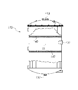
outlet line (29).
[0054] As
mentioned previously, the retained level of CO2 in the product blend supplied
to the final carbonation sparser is fully saturated relative to product
temperature at atmospheric
pressure. Accordingly, the retained volume of CO2 is subtracted from the final
product
carbonation specification. For example, if the required carbonation in the
final product is 3.7
volumes and the deaerated product retains .9 volumes of CO2 based on the
deaeration
CA 03031814 2019-01-23
WO 2018/022671
PCT/US2017/043811
temperature, the final CO2 injection for carbonation will be 2.8 volumes. By
way of one specific
example, the following equations can be used to determine the required amount
of CO2 needed to
be injected for final carbonation:
GasVoldissolved - final carbonation level, per product specification
GasVolumepre-inject = retained CO2 volumes of product blend (at 0 psig)
calculated
according to the following 3rd degree polynomial derived from FIG. 1:
Gas Volume-pre-inject = 3.288 - 0.06613 * (Temp F) + 0.0005850 *
(Temp F)2 - 0.000001976 * (Temp F)3
Gas Offset = the correction for carbonation due to gains or losses due to the
filling
process (based on lab results)
Liquiddth = Total GPM * 0.13368
Gasam is the gas flow setpoint for final carbonation:
Gascr. = (GasVoldissoived + Gas Offset) ¨ GasVolumepre-iniect Liquidcrm
Since the final control will be in lbs/min, Gasefir is converted into lbs/min
as follows:
Gastbsimin = Gasam * 0.11366
Of course, various other mathematical correlations can be used in the same or
similar manner.
[0055] While
the deaerator tank can comprise a simple vented vessel having suitable
connections for introducing the product blend, venting gases and removing
deaerated product, it
has also been found that the vessel can include additional internal features
that facilitate gas
separation in order to reduce the amount of entrained 02 and N2 in the product
blend leaving the
vessel and/or to limit foam production in the vented vessel.
[0056] FIGURE
3 is a schematic elevational view of a generally cylindrical deaerator
tank (112), and FIG. 4 is a partial cross-sectional view of the deaerator tank
(112). Tank (112)
once again operates at atmospheric pressure, and includes an atmospheric vent
(133). The
CA 03031814 2019-01-23
WO 2018/022671
PCT/US2017/043811
21
product blend enters tank (112) through three inlets (131) in order to reduce
the flow velocity.
The inlets (131) are located at the same level, and are spaced apart about a
portion of the
circumference of the tank. During operation, the tank (112) is operated such
that the liquid level
(LL) is at or slightly below the height of the inlets (131). An outlet (132)
is provided at the
bottom of the tank (112) for removing the deaerated product blend for
bottling.
[0057] In
some instances, particularly when bottling low calorie (i.e., "diet")
beverages
containing artificial sweeteners and/or with large fluid throughputs, foam can
be produced in the
upper portion of the deaerator tank and microscopic oxygen bubbles are
entrained in the liquid
leaving the bottom of the deaerator tank. While such problems can be addressed
by using a larger
deaerator tank, the embodiment of FIGS. 3 and 4 includes a coalescer (142) in
the form of a pad,
pack or plate (or series of plates), as well as a foam breaker (140) in the
form of a pad, pack or
plate (or series of plates).
[0058] The
foam breaker (140) is located above the liquid level (LL). In one
embodiment, the foam breaker (140) comprises a series of corrugated metal
plates that break-up
bubbles that pass though the plates, allowing oxygen and nitrogen to be vented
from the tank
(112). Any of a variety of alternative foam breakers can be employed for this
purpose, such as
various types of plates (also referred to as trays), pads, packing (also
referred to as a pack), and
combinations of the foregoing that are configured to break gas bubbles in a
foam.
100591 The
coalescer (142) is located below the surface of the liquid. In one embodiment,
the coalescer (142) comprises a mesh tray that allows smaller gas bubbles in
the liquid to form
larger bubbles that separate more easily from the liquid for subsequent
venting from the tank
(112). Any of a variety of alternative coalescers can be employed for this
purpose, such as
various types of plates (also referred to as trays), pads, packing (also
referred to as a pack), and
combinations of the foregoing that are configured to coalesce small gas
bubbles into larger
bubbles that can more readily escape from the liquid within the tank (112).
[0060] By
employing both a foam breaker (140) and a coalescer (142), the deaerator tank
(112) can be made smaller and/or have improved deaeration. It will also be
understood that the
CA 03031814 2019-01-23
WO 2018/022671
PCT/US2017/043811
22
deaerator tank can include a foam breaker only, or a coalescer only. Likewise,
the deaerator tank
can include more than one foam breaker only and/or more than one coalescer.
[0061]
Finally, while conventional bottling equipment and methods can be used for
bottling the deaerated product blend produced using the systems and methods
described herein,
in order to maintain low levels of 02 and N2 in the packaged product, bottling
should be
performed in a manner that avoids the re-introduction of air into the
container (e.g., a bottle or
can). This may be accomplished, for example, by evacuating air from the
product container
immediately prior to filling (e.g., using a CO2 purge). Alternatively, the
filling equipment can be
designed such that air is not introduced (or only a small amount of air is
introduced into the
container during filling and capping/can seaming.
[0062] While
various embodiments have been described in detail above, it will be
understood that the components, features and configurations, as well as the
methods of
manufacturing the devices and methods described herein are not limited to the
specific
embodiments described herein. Additional features of the invention will become
apparent to
those skilled in the art upon consideration of the description. Modifications
may be made without
departing from the spirit and scope of the invention. The methods and systems
described herein
can be used for oxygen and nitrogen removal from a variety of beverages,
including juices,
alcoholic beverages, soft drinks (aka sodas), flavored waters, energy drinks,
athletic drinks, etc.