Note : Les descriptions sont présentées dans la langue officielle dans laquelle elles ont été soumises.
CA 03032253 2019-01-28
WO 2018/020463
PCT/IB2017/054582
RUTHENIUM IMPREGNATED CERIA CATALYST
FIELD OF THE INVENTION
The present invention relates generally to the field of nitrogen oxides (NOõ)
adsorbers used in the
treatment of a NOR-containing exhaust gas stream and to methods of preparing
and using the same.
BACKGROUND OF THE INVENTION
A major problem encountered inthe treatment of automotive exhaust. gas stream
is the so-called
"cold start" period, which is the time period at the beginning of the
treatment process, when the exhaust gas
stream and the exhaust gas treatment system are at low temperatures (i.e.,
below 150 CC). At these low
temperanues, exhaust gas treatment systems generally do not display sufficient
catalytic activity for
effectively treating hydrocarbons (HC), nitrogen oxides (NOõ) and/or carbon
monoxide ((:O) emissions. As
a result, considerable effi)rts have been made to alleviate this probletn. For
instance, new trapping systems
have been developed, which can store these exhaust gas emissions at low
temperatures and subsequently
release them (i.e., HC, CO and NOx gases) at higher temperatures, when ate
remaining catalytic components
of the treatment, system have attained sufficient catalytic activity.
For example, zeol.ites are often used as adsorbent materials in catalytic
treatment systems in order to
adsorb and retain gaseous hydrocarbon pollutants during the initial cold-start
period. As the exhaust gas
temperature increases, the adsorbed hydrocarbons are driven from :,he
adsorbent material and subjected to
catalytic oxidation at higher temperatures. However, the NOx-adsorber
technology has been limited to use
in lean NO trap (LNT) applications where NO, (NO and NO2) is adsorbed on base
metal oxides (BaO,
MgO, Ce02 etc) under lean conditions and then released and reduced under
transient rich conditions. The
NO to NO2 conversion is a prerequisite to efficient NO trapping, however the
reaction rate is very slow
when temperature is below 200 C, which renders traditional [NT catalyst
unsuitable for trapping of cold-
start NO, emission.
Due to emission regulations becoming increasingly more stringent, it would be
highly desirable to
provide an improved NO storage component to capture cold-start NO emission. As
>80% of cold-start NO
emission consists of NO, it is imperative that advanced NO adsorption
materials have great efficiency for
NO adsorption.
SUMMARY OF THE INVENTION
In general, catalytic components such as SCR catalysts are very effective in
converting NO to N2 at
temperatures above 200 C but do not exhibit sufficient activities at lower
temperature regions (<200 C)
such as that found during cold-start or prolonged low-speed city driving.
Therefore, catalytic components
capable of capturing and storing such low-temperature NO emissions, and being
able to release it at higher
-1-
CA 03032253 2019-01-28
WO 2018/020463 PCT/IB2017/054582
temperatures (>200 C) when catalytic components (i.e. SCR catalysts) become
effective are in great
demand.
As such, the present disclosure generally provides such catalysts, catalyst
articles and catalyst
systems comprising such catalyst articles. In particular, such articles and
systems comprise a NO,, adsorber
suitable for adsorbing NO,, at low temperatures and releasing trapped NO,, at
elevated temperatures. In
particular the NO,, adsorber composition of the current invention maintains
adsorbing properties even in the
presence of water vapor (steam) and carbon dioxide (CO2) compared to
conventional NO,, adsorbers, which
exhibit a lower adsorption capacity in the presence of steam and CO2. The NOõ
adsorber Composition of the
current invention is unique in that it adsorbs NO at. low temperatures, while
previous INT catalysts
primarily adsorb NO2,
In this regard, aspects of the current invention are directed to a low-
temperature NO adsorber
composition comprising an active metal and a metal oxide support, wherein the
metal oxide support
comprises greater than 50% by weight ceria based on the total weight of the
NO,, adsorber composition, and
wherein the active metal comprises about 0.01% to about 5% by weight ruthenium
based on the total weight
of the NO,, adsorber composition. In some embodiments, the NO,, adsorber
composition is substantially free
of zirconium. In some embodiments, the NO,, adsorber composition is
substantially free of barium or
zeolites. In other embodiments, the metal oxide support comprises greater than
90% by weight ceria based
on the total weight of the NO,, adsorber composition. In some embodiments, the
metal oxide support
comprises at least one additional metal oxide, wherein the at least one
additional metal oxide is a rare earth
metal oxide. In some embodiment, the additional metal oxide is selected from
Pr601 1, ZrO2, Gd203, and
combinations thereof. In some embodiment, the additional metal oxide is
present in an amount of about
0.1% to about 10% by weight based on the total weight of the NO,, adsorber
composition. In some
embodiments, the NO,, adsorber composition comprises a surface concentration
of active Ru ions of at least
0.5% by weight based on the total weight of the NO,, adsorber composition. In
some embodiments, the NO,,
adsorber composition adsorbs NO from the exhaust gas stream at a temperature
of about 50 C to about 200
C in an amount of at least 30-60% by weight based on the total amount of NO
present in the exhaust gas
stream. In some embodiments, the low-temperature NO adsorber composition
oxidizes NO present in the
exhaust gas steam to NO2 at a temperature ranging from about 300 C to about
600 'C. In some
embodiments, the low-temperature NO adsorber composition releases NO back into
the exhaust gas stream
at a temperature of about 170 C to about 300 C in an amount of at least 55%
to about 100% by weight
based on the total amount of NO adsorbed onto the NO,, adsorber composition.
In some embodiments, the
catalyst composition is substantially free of any additional active metal. In
some embodiments, the NO,,
adsorber composition is included in a lean NO,, trap.
Another aspect of the invention is directed to a catalyst article comprising a
substrate carrier having
a plurality of channels adapted for gas flow and a NO,, adsorber composition
according to the invention
positioned to contact an exhaust gas passing through each channel. In some
embodiments, the substrate
-2-
CA 03032253 2019-01-28
WO 2018/020463 PCT/IB2017/054582
carrier is a metal or ceramic honeycomb. In another embodiment, the honeycomb
is a wall flow filter
substrate or a flow through substrate. In another embodiment, the NO,,
adsorber is applied to the substrate
carrier with a loading of at least about 0.5 Win'. In another embodiment, the
active metal is present in an
amount of about 10 to about 200 g/ft3. In some embodiments, the catalyst
article further comprises a second
catalyst composition, wherein the second catalyst composition comprises a DOC
catalyst composition or a
LNT catalyst composition; and wherein the second catalyst composition is
layered or zoned on the substrate
carrier with the NO,, adsorber composition. In some embodiments, the second
catalyst composition is
disposed directly on the substrate carrier.
Another aspect of the invention is directed to an exhaust gas treatment system
comprising a NO,,
adsorber composition and an SCR catalyst positioned downstream from an
internal combustion engine. In
some embodiments, the NO,, adsorber composition is disposed on a substrate
carrier and is positioned
upstream of the SCR catalyst. In another embodiment, the NO,, adsorber
composition and SCR catalyst are
disposed on the same substrate. In another embodiment, the internal combustion
engine is a gasoline or a
diesel engine.
The invention includes, without limitation, the following embodiments.
Embodiment 1: A low-temperature NO adsorber composition comprising: an active
metal and a metal
oxide support, wherein the metal oxide support comprises greater than 50% by
weight ceria based on the
total weight of the NOx adsorber composition, and wherein the active metal
comprises about 0.01% to about
5% by weight ruthenium based on the total weight of the NO,, adsorber
composition.
Embodiment 2: The low-temperature NO adsorber composition of any preceding or
subsequent
embodiment, wherein the low-temperature NO adsorber composition is
substantially free of zirconium.
Embodiment 3: The low-temperature NO adsorber composition of any preceding or
subsequent
embodiment, wherein the low-temperature NO adsorber composition is
substantially free of barium or
zeolite.
Embodiment 4: The low-temperature NO adsorber composition of any preceding or
subsequent
embodiment, wherein the metal oxide support comprises greater than 90% by
weight ceria based on the total
weight of the NO,, adsorber.
Embodiment 5: The low-temperature NO adsorber composition of any preceding or
subsequent
embodiment, wherein the metal oxide support comprises at least one additional
metal oxide, wherein the at
least one additional metal oxide is a rare earth metal oxide.
Embodiment 6: The low-temperature NO adsorber composition of any preceding or
subsequent
embodiment, wherein the at least one additional metal oxide is selected from
Pr6011, ZrO2, Gd203, and
combinations thereof.
Embodiment 7: The low-temperature NO adsorber composition of any preceding or
subsequent
embodiment, wherein the metal oxide support comprises at least one additional
metal oxide in an amount of
about 0.1% to about 10% by weight based on the total weight of the NOx
adsorber composition.
-3-
CA 03032253 2019-01-28
WO 2018/020463 PCT/IB2017/054582
Embodiment 8: The low-temperature NO adsorber composition of any preceding or
subsequent
embodiment, wherein the NO,, adsorber composition comprises a surface
concentration of active Ru ions of
at least 0.5% by weight based on the total weight of the NO,, adsorber
composition.
Embodiment 9: The low-temperature NO adsorber composition of any preceding or
subsequent
embodiment, wherein the NO,, adsorber composition adsorbs NO from the exhaust
gas stream at a
temperature of about 50 C to about 200 C in an amount of at least 30-60% by
weight based on the total
amount of NO present in the exhaust gas stream.
Embodiment 10: The low-temperature NO adsorber composition of any preceding or
subsequent
embodiment, wherein the NO,, adsorber composition oxidizes NO present in the
exhaust gas steam to NO2 at
a temperature ranging from about 300 'V to about 600 'C.
Embodiment 11: The low-temperature NO adsorber composition of any preceding or
subsequent
embodiment, wherein the NO,, adsorber composition releases NO back into the
exhaust gas stream at a
temperature of about 170 'V to about 300 C in an amount of at least 55 to
about 100% by weight based on
the total amount of NO adsorbed onto the NO,, adsorber composition.
Embodiment 12: The low-temperature NO adsorber composition of any preceding or
subsequent
embodiment, wherein the NO,, adsorber composition is substantially free of any
additional active metal.
Embodiment 13: The low-temperature NO adsorber composition of any preceding or
subsequent
embodiment, wherein the NO,, adsorber composition is comprised in a lean NO,,
trap.
Embodiment 14: A catalyst article comprising a catalyst substrate carrier
having a plurality of channels
adapted for gas flow and a low temperature NO,, adsorber composition according
to any preceding or
subsequent embodiment positioned to contact an exhaust gas passing through
each channel.
Embodiment 15: The catalyst article of any preceding or subsequent embodiment,
wherein the substrate
carrier is a metal or ceramic honeycomb.
Embodiment 16: The catalyst article of any preceding or subsequent embodiment,
wherein the honeycomb
is a wall flow filter substrate or a flow through substrate.
Embodiment 17: The catalyst article of any preceding or subsequent embodiment,
wherein the low
temperature NO,, adsorber composition is applied to the substrate carrier with
a loading of at least about 0.5
g/in3.
Embodiment 18: The catalyst article of any preceding or subsequent embodiment,
wherein the active metal
is present in an amount of about 10 to about 200 g/ft3.
Embodiment 19: The catalyst article of any preceding or subsequent embodiment,
further comprising a
second catalyst composition, wherein the second catalyst composition comprises
a DOC catalyst
composition or a LNT catalyst composition; and wherein the second catalyst
composition is layered or
zoned on the substrate carrier with the NO,, adsorber catalyst composition.
Embodiment 20: The catalyst article of any preceding or subsequent embodiment,
wherein the second
catalyst composition is disposed directly on the substrate carrier.
-4-
CA 03032253 2019-01-28
WO 2018/020463 PCT/IB2017/054582
Embodiment 21: An exhaust gas treatment system comprising a low-temperature NO
adsorber composition
according to any preceding or subsequent embodiment and an SCR catalyst
disposed downstream from an
internal combustion engine.
Embodiment 22: The exhaust gas treatment system of any preceding or subsequent
embodiment, wherein
.. the low-temperature NO adsorber composition is present on a substrate
carrier positioned upstream of the
SCR catalyst.
Embodiment 23: The exhaust gas treatment system of any preceding or subsequent
embodiment, wherein
the low-temperature NO adsorber composition and SCR catalyst are disposed on
the same substrate carrier.
Embodiment 24: The exhaust gas treatment system of any preceding or subsequent
embodiment, wherein
the internal combustion engine is a gasoline or a diesel engine.
These and other features, aspects, and advantages of the disclosure will be
apparent from a reading
of the following detailed description together with the accompanying drawings,
which are briefly described
below. The invention includes any combination of two, three, four, or more of
the above-noted
embodiments as well as combinations of any two, three, four, or more features
or elements set forth in this
disclosure, regardless of whether such features or elements are expressly
combined in a specific embodiment
description herein. This disclosure is intended to be read holistically such
that any separable features or
elements of the disclosed invention, in any of its various aspects and
embodiments, should be viewed as
intended to be combinable unless the context clearly dictates otherwise. Other
aspects and advantages of the
present invention will become apparent from the following.
BRIEF DESCRIPTION OF THE DRAWINGS
In order to provide an understanding of embodiments of the invention,
reference is made to the
appended drawings, which are not necessarily drawn to scale, and in which
reference numerals refer to
components of exemplary embodiments of the invention. The drawings are
exemplary only, and should not
be construed as limiting the invention.
FIG. 1 is a perspective view of a honeycomb-type substrate carrier which may
comprise a catalyst
article (i.e., low-temperature NO adsorber (LT-NA)) washcoat composition in
accordance with the present
invention;
FIG. 2 is a partial cross-sectional view enlarged relative to FIG. 1 and taken
along a plane parallel to
the end faces of the substrate carrier of FIG. 1, which shows an enlarged view
of a plurality of the gas flow
passages shown in FIG. 1, in an embodiment wherein the substrate carrier is a
monolithic flow-through
substrate;
FIG. 3 is a cutaway view of a section enlarged relative to FIG. 1, wherein the
honeycomb-type
substrate carrier in FIG.1 represents a wall flow filter substrate monolith;
FIG. 4A shows a schematic depiction of an embodiment of an emission treatment
system in which a
low-temperature NO adsorber (LT-NA) of the present invention is utilized,
wherein the LT-NA is located
-5-
CA 03032253 2019-01-28
WO 2018/020463 PCT/IB2017/054582
downstream of a diesel oxidation catalyst (DOC) and upstream of a catalyzed
soot filter (CSF) and selective
catalytic reduction catalyst (SCR);
FIG. 4B shows a schematic depiction of an embodiment of an emission treatment
system in which a
low-temperature NO adsorber (LT-NA) of the present invention is utilized,
wherein the LT-NA is located
upstream of a diesel oxidation catalyst (DOC), a catalyzed soot filter (CSF),
and selective catalytic reduction
catalyst (SCR);
FIG. 4C shows a schematic depiction of an embodiment of an emission treatment
system in which a
low-temperature NO adsorber (LT-NA) of the present invention is utilized,
wherein the LT-NA is located
downstream of a diesel oxidation catalyst (DOC) and upstream of a selective
catalytic reduction catalyst
(SCR) and a catalyzed soot filter (CSF);
FIG. 4D shows a schematic depiction of an embodiment of an emission treatment
system in which a
low-temperature NO adsorber (LT-NA) of the present invention is utilized,
wherein the LT-NA is located
upstream of a diesel oxidation catalyst (DOC), a selective catalytic reduction
catalyst (SCR) and a catalyzed
soot filter (CSF);
FIG. 5A shows a schematic depiction of an embodiment of an emission treatment
system in which a
low-temperature NO adsorber of the present invention combined with a diesel
oxidation catalyst (LT-
NA/DOC) is utilized, wherein the LT-NA/DOC is located upstream of a catalyzed
soot filter (CSF) and
selective catalytic reduction catalyst (SCR);
FIG. 5B shows a schematic depiction of an embodiment of an emission treatment
system in which a
low-temperature NO adsorber of the present invention combined with a diesel
oxidation catalyst (LT-
NA/DOC) is utilized, wherein the LT-NA/DOC is located upstream of a catalyzed
soot filter (CSF) and
selective catalytic reduction catalyst (SCR);
FIG. 5C shows a schematic depiction of an embodiment of an emission treatment
system in which a
low-temperature NO adsorber of the present invention combined with a diesel
oxidation catalyst (LT-
NA/DOC) is utilized, wherein the LT-NA/DOC is located upstream of a combined
selective catalytic
reduction catalyst catalyzed soot filter (SCRoF);
FIG. 5D shows a schematic depiction of an embodiment of an emission treatment
system in which a
low-temperature NO adsorber of the present invention combined with a catalyzed
soot filter (LT-NA/CSF)
is utilized, wherein the LT-NA/CSF is located upstream of a diesel oxidation
catalysts (DOC) and
downstream of a selective catalytic reduction catalyst (SCR);
FIG. 5E shows a schematic depiction of an embodiment of an emission treatment
system in which a
low-temperature NO adsorber of the present invention combined with a selective
catalytic reduction
catalyst (LT-NA/SCR) is utilized, wherein the LT-NA/SCR is located upstream of
a catalyzed soot filter
(CSF) and a diesel oxidation catalysts (DOC);
FIG. 5F shows a schematic depiction of an embodiment of an emission treatment
system in which a
low-temperature NO adsorber of the present invention combined with a joint
selective catalytic reduction
-6-
CA 03032253 2019-01-28
WO 2018/020463 PCT/IB2017/054582
catalyst/catalyzed soot filter (LT-NA/SCRoF) is utilized, wherein the LT-
NA/SCROF is located upstream of
a diesel oxidation catalysts (DOC);
FIG. 6A shows a cross-sectional view of a zoned NO,, adsorber composition of
the present
invention;
FIG. 6B shows a cross-sectional view of a layered NO,, adsorber composition of
the present
invention;
FIG. 7 is a line graph showing catalyst-out NO and NO2 concentration of
catalyst compositions
containing ceria (Ce02) and ceria containing 2% ruthenium (Ru);
FIG. 8 is a line of graph showing the presence or absence of RuO2 phase
present for ruthenium
impregnated alumina and ceria supports measured by X-ray diffraction (XRD);
FIG. 9 is a line graph showing NO,, conversion and release as a function of
temperature for catalyst
compositions having different ruthenium concentrations;
FIG. 10 is a line graph showing the catalyst outlet NO concentration as a
function of time of various
catalyst composition samples during 0-300 s of WHTC cycle;
FIG. 11 is a line graph showing the difference of cumulative NO,, of inlet and
outlet (i.e., delta NOR)
as a function of time for various catalyst composition samples; and
FIG. 12 is a line graph showing the cumulative NO2 concentration as a function
of time of various
catalyst composition samples; wherein the catalyst compositions of the current
invention adsorb NO2 at low
temperature and catalyze NO to NO2 oxidation at greater than 300 'C.
DETAILED DESCRIPTION OF THE PREFERRED EMBODIMENTS
The present invention now will be described more fully hereinafter. This
invention may, however,
be embodied in many different forms and should not be construed as limited to
the embodiments set forth
herein; rather, these embodiments are provided so that this disclosure will be
thorough and complete, and
will fully convey the scope of the invention to those skilled in the art. As
used in this specification and the
claims, the singular forms "a," "an," and "the" include plural referents
unless the context clearly dictates
otherwise.
The present disclosure provides catalysts, catalyst articles and catalyst
systems comprising such
catalyst articles suitable for the adsorption and subsequent thermal release
of NOR. In particular, such
articles and systems comprise a NO,, adsorber suitable for adsorbing NO,, at
low temperatures (LT-NA) and
thermally releasing trapped NO,, at elevated temperatures. This is of
particular importance when the low-
temperature NO,, adsorber is placed upstream of a SCR catalyst that is very
effective in converting NO,, to
N2 at temperatures above 200 'V, but does not exhibit sufficient activities at
lower temperature regions
(<200 C) such as during cold-start and before urea can be injected into the
exhaust. Beneficially, the NO,,
adsorber of the current invention maintains adsorbing properties even in the
presence of steam and carbon
-7-
CA 03032253 2019-01-28
WO 2018/020463 PCT/IB2017/054582
dioxide in contrast to conventional NO,, adsorbers, which exhibit a decline in
adsorption capacity when
steam and CO2 is present.
As used herein, the term "catalyst" or "catalyst composition" refers to a
material that promotes a
reaction. As used herein, the phrase "catalyst system" refers to a combination
of two or more catalysts, for
example a combination of a first low-temperature NO adsorber (LT-NA) catalyst
and a second catalyst
which may be a diesel oxidation catalyst (DOC), a lean NO,, trap (LNT) or a
selective catalytic reduction
(SCR) catalyst. The catalyst system may alternatively be in the form of a
washcoat in which the two
catalysts are mixed together or coated in separate layers.
As used herein, the terms "upstream" and "downstream" refer to relative
directions according to the
flow of an engine exhaust gas stream from an engine towards a tailpipe, with
the engine in an upstream
location and the tailpipe and any pollution abatement articles such as filters
and catalysts being downstream
from the engine.
As used herein, the term "stream" broadly refers to any combination of flowing
gas that may contain
solid or liquid particulate matter. The term "gaseous stream" or "exhaust gas
stream" means a stream of
gaseous constituents, such as the exhaust of a combustion engine, which may
contain entrained non-gaseous
components such as liquid droplets, solid particulates, and the like. The
exhaust gas stream of a combustion
engine typically further comprises combustion products (CO2 and H20), products
of incomplete combustion
(carbon monoxide (CO) and hydrocarbons (HC)), oxides of nitrogen (N0,),
combustible and/or
carbonaceous particulate matter (soot), and un-reacted oxygen and nitrogen.
As used herein, the term "substrate" refers to the monolithic material onto
which the catalyst
composition is placed.
As used herein, the term "support" refers to any high surface area material,
usually a metal oxide
material, upon which a catalytic precious metal is applied.
As used herein, the term "washcoat" has its usual meaning in the art of a
thin, adherent coating of a
catalytic or other material applied to a substrate material, such as a
honeycomb-type carrier member, which
is sufficiently porous to permit the passage of the gas stream being treated.
A washcoat is formed by
preparing a slurry containing a certain solid content (e.g., 30%-90% by
weight) of particles in a liquid
vehicle, which is then coated onto a substrate and dried to provide a washcoat
layer.
As used herein, the term "catalyst article" refers to an element that is used
to promote a desired
reaction. For example, a catalyst article may comprise a washcoat containing
catalytic compositions on a
substrate.
As used herein, "impregnated" or "impregnation" refers to permeation of the
catalytic material into
the porous structure of the support material.
-8-
CA 03032253 2019-01-28
WO 2018/020463 PCT/IB2017/054582
Catalyst Composition
The low-temperature NO adsorber (LT-NA) composition of the invention comprises
an active
metal impregnated onto a metal oxide support, wherein the active metal is
predominately ruthenium. As
used therein "predominantly" ruthenium refers to an amount of ruthenium of at
least 50% by weight based
on the total amount of active metal present. As used herein, "active metal"
refers to platinum group metals
or oxides thereof, including platinum (Pt), palladium (Pd), ruthenium (Ru),
rhodium (Rh), osmium (Os),
iridium (Jr), and mixtures thereof. The concentration of active metal
ruthenium can vary, but will typically
be from about 0.01 wt% to about 5 wt% relative to the total weight of the
impregnated metal oxide support.
In some embodiments, the NO,, adsorber composition is substantially free of
any further active metal. As
used herein, the term "substantially free of additional active metal" means
that there is no additional active
metal intentionally added to the NO,, adsorber composition, and that there is
less than about 0.01wt% of an
additional active metal by weight present in the NO,, adsorber composition.
In other embodiments, the NO,, adsorber composition contains another active
metal, such as in a
weight ratio of about 1:10 to about 10:1, more typically in a weight ratio of
ruthenium to other active metal
equal to or greater than about 1:1, equal to or greater than about 2:1, or
equal to or greater than about 5:1. In
each instance, in some embodiments, the listed ratio may have an upper limit
of a ratio of 10:1.
As used herein, "metal oxide support" refers to metal-containing oxide
materials exhibiting
chemical and physical stability at high temperatures, such as the temperatures
associated with diesel engine
exhaust. In some embodiments, the metal oxide support comprises greater than
50% by weight ceria based
on the total weight of the NO,, adsorber composition. In further embodiments,
the metal oxide support
comprises greater than about 60%, or greater than about 70%, or greater than
about 80%, or greater than
about 90% by weight ceria based on the total weight of the NO,, adsorber
composition. In additional
embodiments, the metal oxide support comprises from about 50% to about 99.9%,
or from about 70% to
about 99.5%, or from about 80% to about 99.0% by weight ceria based on the
total weight of the NO,,
adsorber composition. In additional embodiments, the metal oxide support
comprises 100.0% by weight
ceria based on the total weight of the NO,, adsorber composition.
In some embodiments, additional metal oxides can be combined as physical
mixtures or chemical
combinations with ceria to form the metal oxide support. Examples of
additional metal oxides include
alumina, silica, zirconia, titania, or a combination thereof. In some
embodiments, additional metal oxides
include rare earth metal oxides, e.g., Y, La, Pr, Nd, Pm, Sm, Eu, Gd, Tb, Dy,
Ho, Er, Tm, Yb, Lu, or a
combination thereof. In some embodiments, the additional metal oxide is
selected from Pr601 1, ZrO2,
Gd203, and combinations thereof. In some embodiments, the total amount of the
additional metal oxide
ranges from about 0.1% to about 10%, preferably from about 1% to about 5%, by
weight based on the total
weight of the NO,, adsorber composition (or less than 10%, or less than 9%, or
less than 8%, or less than 7%,
or less than 6%, or less than 5%, or less than 4%, or less than 3%, or less
than 2%, or less than 1%, or less
than 0.5% by weight based on the total weight of the NO,, adsorber
composition).
-9-
CA 03032253 2019-01-28
WO 2018/020463 PCT/IB2017/054582
In some embodiments, the metal oxide support comprises atomically-doped
combinations of metal
oxides. For example, in some embodiments, the metal oxide support comprises
atomically-doped
combinations of metal oxides containing a dopant metal selected from Si, Nb,
Zr, and combinations thereof.
In some embodiments, atomically-doped combinations of metal oxides comprise at
least one rare earth metal
oxide or a combination thereof. For example, in some embodiments, the at least
one rare earth metal oxide
is modified to contain a dopant metal in oxide form, the dopant metal being
selected from Y, La, Pr, Nd, Pm,
Sm, Eu, Gd, Tb, Dy, Ho, Er, Tm, Yb, Lu and combinations thereof. In some
embodiments, the dopant metal
is Pr, Gd, Zr, or a combination thereof. In some embodiments, the total amount
of the dopant metal ranges
from about 0.1% to about 10%, preferably from about 1% to about 5% by weight
based on the total weight
of the NO,, adsorber composition (less than 10%, less than 9%, less than 8%,
less than 7%, less than 6%, less
than 5%, less than 4%, less than 3%, less than 2%, less than 1%, or less than
0.5% by weight based on the
total weight of the NO,, adsorber composition).
In other embodiment the NO,, adsorber composition is substantially free of
zirconium. In some
embodiments, the catalyst composition is substantially free of barium or
zeolite. As used herein, the term
"substantially free of zirconium" or "substantially free of barium or zeolite"
means that there is no zirconium
or barium or zeolite intentionally added to the NO,, adsorber composition, and
that there is less than about
5% of zirconium or barium or zeolite by weight in the NO,, adsorber
composition. As such, in specific
embodiments, there is less than about 5% by weight, less than about 4%, less
than about 3%, less than about
2%, or less than about 1% by weight of zirconium or barium or zeolite present
in the NO,, adsorber
composition.
In some embodiments, the NO,, adsorber composition comprises a surface
concentration of Ru ions
of at least 0.5% by weight based on the total weight of the NO,, adsorber
composition, as measured by x-ray
photoelectron spectroscopy (XPS). Without intending to be bound by theory, it
is thought that the
concentration of active Ru ions (e.g., ions having an oxidation state of Ru
(+IV), Ru (+VI) or any oxidation
state in between) can be correlated to the extent of catalytic activity
provided by Ru metal. For example, the
same amount of Ru can be impregnated onto various metal oxides supports
comprising different active Ru
ion concentrations and hence NO,, adsorbing efficiencies. For example, XPS
measurements have shown that
metal oxide supports, in terms of their active Ru species surface
concentration can be ranked as follows:
Ce02 >Zr02> Ce02-ZrO2-Y203-La203> A1203>Ti02, wherein the Ru concentration is
2% by weight based
on the total weight of the NOx adsorber composition. Likewise, measurements
have shown that NO,,
adsorbing efficiencies can be ranked as follows: Ce02 >Zr02> Ce02-ZrO2-Y203-
La203>A1203>Ti02. Since
both rankings are essentially identical, active Ru ion surface concentration
may be used as a reasonable
guide to determine relative NO,, adsorbing efficiencies of the catalytic
composition.
-10-
CA 03032253 2019-01-28
WO 2018/020463 PCT/IB2017/054582
Substrate Carrier
According to one or more embodiments, the substrate carrier for the
composition of a low-
temperature NO,, adsorber may be constructed of any material typically used
for preparing automotive
catalysts and will typically comprise a metal or ceramic honeycomb structure.
The substrate typically
provides a plurality of wall surfaces upon which the washcoat composition is
applied and adhered, thereby
acting as a substrate carrier for the catalyst composition.
Exemplary metallic substrate carriers include heat resistant metals and metal
alloys, such as titanium
and stainless steel as well as other alloys in which iron is a substantial or
major component. Such alloys
may contain one or more of nickel, chromium, and/or aluminum, and the total
amount of these metals may
advantageously comprise at least 15 wt% of the alloy, e.g., 10-25 wt% of
chromium, 3-8 wt% of aluminum,
and up to 20 wt% of nickel. The alloys may also contain small or trace amounts
of one or more other
metals, such as manganese, copper, vanadium, titanium and the like. The
surface of the metal substrate
carriers may be oxidized at high temperatures, e.g., 1000 C and higher, to
form an oxide layer on the surface
of the substrate carrier, improving the corrosion resistance of the alloy and
facilitating adhesion of the
washcoat layer to the metal surface.
Ceramic materials used to construct the substrate carrier may include any
suitable refractory
material, e.g., cordierite, mullite, cordierite-a alumina, silicon nitride,
zircon mullite, spodumene, alumina-
silica magnesia, zircon silicate, sillimanite, magnesium silicates, zircon,
petalite, a alumina, aluminosilicates
and the like.
Any suitable substrate design may be employed, such as a monolithic flow-
through substrate having
a plurality of fine, parallel gas flow passages extending from an inlet to an
outlet face of the substrate such
that passages are open to fluid flow. The passages, which are essentially
straight paths from the inlet to the
outlet, are defined by walls on which the catalytic material is coated as a
washcoat so that the gases flowing
through the passages contact the catalytic material. The flow passages of the
monolithic substrate are thin-
walled channels which can be of any suitable cross-sectional shape, such as
trapezoidal, rectangular, square,
sinusoidal, hexagonal, oval, circular, and the like. Such structures may
contain from about 60 to about 1200
or more gas inlet openings (i.e., "cells") per square inch of cross section
(cpsi), more usually from about 300
to 600 cpsi. The wall thickness of flow-through substrates can vary, with a
typical range being between
0.002 and 0.1 inches. A representative commercially-available flow-through
substrate is a cordierite
substrate having 400 cpsi and a wall thickness of 6 mil, or 600 cpsi and a
wall thickness of 4 mil. However,
it will be understood that the invention is not limited to a particular
substrate type, material, or geometry.
In alternative embodiments, the substrate carrier may be a wall-flow
substrate, wherein each passage
is blocked at one end of the substrate body with a non-porous plug, with
alternate passages blocked at
opposite end-faces. This requires that gas flow through the porous walls of
the wall-flow substrate to reach
the exit. Such monolithic substrates may contain up to about 700 or more cpsi,
such as about 100 to 400
cpsi and more typically about 200 to about 300 cpsi. The cross-sectional shape
of the cells can vary as
-11-
CA 03032253 2019-01-28
WO 2018/020463 PCT/IB2017/054582
described above. Wall-flow substrates typically have a wall thickness between
0.002 and 0.1 inches. A
representative commercially available wall-flow substrate is constructed from
a porous cordierite, an
example of which has 200 cpsi and 10 mil wall thickness or 300 cpsi with 8 mil
wall thickness, and wall
porosity between 45-65%. Other ceramic materials such as aluminum-titanate,
silicon carbide and silicon
nitride are also used in wall-flow filter substrates. However, it will be
understood that the invention is not
limited to a particular substrate type, material, or geometry. Note that where
the substrate carrier is a wall-
flow substrate, the NO,, adsorber composition can permeate into the pore
structure of the porous walls (i.e.,
partially or fully occluding the pore openings) in addition to being disposed
on the surface of the walls.
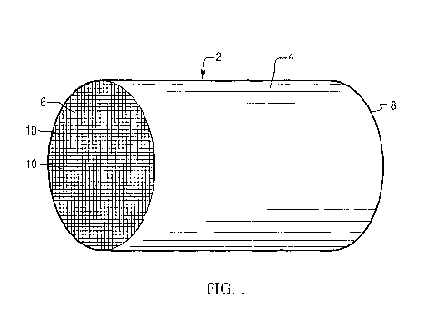
FIGS. 1 and 2 illustrate an exemplary substrate 2 in the form of a flow-
through substrate coated with
a washcoat composition as described herein. Referring to FIG. 1, the exemplary
substrate 2 has a cylindrical
shape and a cylindrical outer surface 4, an upstream end face 6 and a
corresponding downstream end face 8,
which is identical to end face 6. Substrate 2 has a plurality of fine,
parallel gas flow passages 10 formed
therein. As seen in FIG. 2, flow passages 10 are formed by walls 12 and extend
through carrier 2 from
upstream end face 6 to downstream end face 8, the passages 10 being
unobstructed so as to permit the flow
of a fluid, e.g., a gas stream, longitudinally through carrier 2 via gas flow
passages 10 thereof. As more
easily seen in FIG. 2, walls 12 are so dimensioned and configured that gas
flow passages 10 have a
substantially regular polygonal shape. As shown, the washcoat composition can
be applied in multiple,
distinct layers if desired. In the illustrated embodiment, the washcoat
consists of both a discrete bottom
washcoat layer 14 adhered to the walls 12 of the carrier member and a second
discrete top washcoat layer 16
coated over the bottom washcoat layer 14. The present invention can be
practiced with one or more (e.g., 2,
3, or 4) washcoat layers and is not limited to the illustrated two-layer
embodiment.
Alternatively, FIGS. 1 and 3 can illustrate an exemplary substrate 2 in the
form a wall flow filter
substrate coated with a washcoat composition as described herein. As seen in
FIG. 3, the exemplary
substrate 2 has a plurality of passages 52. The passages are tubularly
enclosed by the internal walls 53 of the
filter substrate. The substrate has an inlet end 54 and an outlet end 56.
Alternate passages are plugged at the
inlet end with inlet plugs 58, and at the outlet end with outlet plugs 60 to
form opposing checkerboard
patterns at the inlet 54 and outlet 56. A gas stream 62 enters through the
unplugged channel inlet 64, is
stopped by outlet plug 60 and diffuses through channel walls 53 (which are
porous) to the outlet side 66.
The gas cannot pass back to the inlet side of walls because of inlet plugs 58.
The porous wall flow filter
used in this invention is catalyzed in that the wall of said element has
thereon or contained therein one or
more catalytic materials. Catalytic materials may be present on the inlet side
of the element wall alone, the
outlet side alone, both the inlet and outlet sides, or the wall itself may
consist all, or in part, of the catalytic
material. This invention includes the use of one or more layers of catalytic
material on the inlet and/or outlet
walls of the element.
In some embodiments, each catalyst composition of the current invention is
supported on their own
individual substrate carrier. For example, in some embodiments, catalyst
compositions such as low-
-12-
CA 03032253 2019-01-28
WO 2018/020463 PCT/IB2017/054582
temperature NO,, adsorber composition, SCR composition, DOC composition,
catalytic soot filter (CSF),
SCR/soot filter component (SCRoF) can all be supported on their own individual
substrate carrier. Each
substrate carrier may be the same or different.
In some embodiments, however the same substrate carrier may be used for
multiple catalyst
compositions of the invention. For example, the substrate carrier can be
coated with at least two catalyst
compositions contained in a separate washcoat slurries in an axially zoned
configuration. For example, the
same substrate carrier is coated with washcoat slurry of one catalyst
composition and a washcoat slurry of
another catalyst composition, wherein each catalyst composition is different.
This may be more easily
understood by reference to FIG. 6A, which shows an embodiment in which the
first washcoat zone 24 and
the second washcoat zone 26 are located side by side along the length of the
substrate carrier 22. The first
washcoat zone 24 of specific embodiments extends from the inlet end 25 of the
substrate carrier 22 through
the range of about 5% to about 95% of the length of the substrate carrier 22.
The second washcoat zone 26
extends from the outlet 27 of the substrate carrier 22 from about 5% to about
95% of the total axial length of
the substrate carrier 22. The catalyst compositions of at least two components
within a treatment system as
described in the current invention can be zoned onto the same substrate
carrier. In some embodiments, the
catalyst composition of a low-temperature NO adsorber and an SCR component are
zoned onto the same
substrate carrier. For example referring back to FIG.6A, the first washcoat
zone 24 represents the catalyst
composition of the low-temperature NO adsorber and extends from the inlet end
25 of the substrate carrier
through the range of about 5% to about 95% of the length of the substrate
carrier 22. Hence, the second
washcoat zone 26 comprising the SCR component is located side by side to zone
24 extending from the
outlet 27 of the substrate carrier 22. In one embodiment, the first washcoat
zone 24 can represent the SCR
component and the second washcoat zone 26 con comprise the low-temperature NO
adsorber composition.
In other embodiments, the catalyst composition of a DOC and a low-temperature
NO adsorber are
zoned onto the same substrate carrier. For example referring back to FIG.6A,
the first washcoat zone 24
represents the catalyst composition of the low-temperature NO adsorber and
extends from the inlet end 25
of the substrate carrier through the range of about 5% to about 95% of the
length of the substrate carrier 22.
Hence, the second washcoat zone 26 comprising the DOC component is located
side by side to zone 24
extending from the outlet 27 of the substrate carrier 22. In one embodiment,
the first washcoat zone 24 can
represent the DOC component and the second washcoat zone 26 con comprise the
low-temperature NO,,
adsorber composition.
In other embodiments, the catalyst composition of a soot filter and a low-
temperature NO adsorber
are zoned onto the same substrate carrier. For example referring back to
FIG.6A, the first washcoat zone 24
represents the catalyst composition of the low-temperature NO adsorber and
extends from the inlet end 25
of the substrate carrier through the range of about 5% to about 95% of the
length of the substrate carrier 22.
Hence, the second washcoat zone 26 comprising the soot filter component is
located side by side to zone 24
extending from the outlet 27 of the substrate carrier 22. In one embodiment,
the first washcoat zone 24 can
-13-
CA 03032253 2019-01-28
WO 2018/020463 PCT/IB2017/054582
represent the soot filter component and the second washcoat zone 26 con
comprise the low-temperature NO,,
adsorber composition.
In other embodiments, the catalyst composition of a soot filter and a low-
temperature NO adsorber
are zoned onto the same substrate carrier. For example referring back to
FIG.6A, the first washcoat zone 24
represents the catalyst composition of the low-temperature NO adsorber and
extends from the inlet end 25
of the substrate carrier through the range of about 5% to about 95% of the
length of the substrate carrier 22.
Hence, the second washcoat zone 26 comprising the soot filter/SCR component is
located side by side to
zone 24 extending from the outlet 27 of the substrate carrier 22. In one
embodiment, the first washcoat zone
24 can represent the soot filter/SCR component and the second washcoat zone 26
con comprise the low-
temperature NO,, adsorber composition. In additional embodiments, the same
substrate carrier is zoned
using three different catalyst compositions.
In some embodiments, however the same substrate carrier is layered with at
least two catalyst
compositions contained in separate washcoat slurries in a horizontal
configuration. For example, the same
substrate carrier is coated with washcoat slurry of one catalyst composition
and a washcoat slurry of another
catalyst composition, wherein each catalyst composition is different. This may
be more easily understood
by reference to FIG. 6B, which shows an embodiment in which the first washcoat
zone 34 is deposited on
substrate carrier 32 and the second washcoat zone 36 is layered on top of the
first washcoat zone 36 to
render the coated substrate carrier 30. The first washcoat zone 34 and the
second washcoat zone 36 are
deposited over the entire length of the substrate carrier 32, i.e., from inlet
35 to outlet 37. For example
referring back to FIG. 6B, the first washcoat zone 34 represents a DOC
composition coating substrate carrier
32, while the second washcoat zone 36 represents the catalyst composition of
the low-temperature NO,,
adsorber and is layered on top of the first washcoat zone 34, wherein both
washcoat zones extend from inlet
35 to outlet 37. In one embodiment, the first washcoat zone 34 can represent
the composition of the low-
temperature NO,, adsorber, while the DOC composition in the second washcoat
zone 36 is layered on top of
the first washcoat zone 34.
In some embodiments, referring back to FIG. 6B, the first washcoat zone 34
represents a SCR
composition coating substrate carrier 32, while the second washcoat zone 36
represents the catalyst
composition of the low-temperature NO adsorber and is layered on top of the
first washcoat zone 34,
wherein washcoat both zones extend from inlet 35 to outlet 37. In one
embodiment, the first washcoat zone
34 can represent the composition of the low-temperature NO adsorber, while the
SCR composition in the
second washcoat zone 36 is layered on top of the first washcoat zone 34.
In some embodiments, referring back to FIG. 6B, the first washcoat zone 34
represents a soot filter
composition coating substrate carrier 32, while the second washcoat zone 36
represents the catalyst
composition of the low-temperature NO adsorber and is layered on top of the
first washcoat zone 34,
wherein washcoat both zones extend from inlet 35 to outlet 37. In one
embodiment, the first washcoat zone
-14-
CA 03032253 2019-01-28
WO 2018/020463 PCT/IB2017/054582
34 can represent the composition of the low-temperature NO adsorber, while the
soot filter composition in
the second washcoat zone 36 is layered on top of the first washcoat zone 34.
In some embodiments, referring back to FIG. 6B, the first washcoat zone 34
represents a soot
filter/SCR composition coating substrate carrier 32, while the second washcoat
zone 36 represents the
catalyst composition of the low-temperature NO adsorber and is layered on top
of the first washcoat zone
34, wherein washcoat both zones extend from inlet 35 to outlet 37. In one
embodiment, the first washcoat
zone 34 can represent the composition of the low-temperature NO adsorber,
while the soot filter/SCR
composition in the second washcoat zone 36 is layered on top of the first
washcoat zone 34.
In describing the quantity of washcoat or catalytic metal components or other
components of the
composition, it is convenient to use units of weight of component per unit
volume of catalyst substrate.
Therefore, the units, grams per cubic inch ("g/n3") and grams per cubic foot
("g/ft3") are used herein to
mean the weight of a component per volume of the substrate, including the
volume of void spaces of the
substrate. Other units of weight per volume such as g/L are also sometimes
used. The total loading of the
catalyst composition on the substrate carrier, such as a monolithic flow-
through substrate, is typically from
about 0.1 to about 6 g/in3, and more typically from about 0.5 to about 4
g/in3. Total loading of the active
metal without support material (i.e., Ruthenium) is typically in the range of
about 10 to about 200 g/ft3 for
each individual catalyst substrate.
It is noted that these weights per unit volume are typically calculated by
weighing the catalyst
substrate before and after treatment with the catalyst washcoat composition,
and since the treatment process
involves drying and calcining the catalyst substrate at high temperature,
these weights represent an
essentially solvent-free catalyst coating since all of the water of the
washcoat slurry has been removed.
Method of Making the Catalyst Composition
Preparation of the active metal-impregnated metal oxide support typically
comprises impregnating
the metal oxide support in particulate form with an active metal solution,
such as a ruthenium precursor
solution. The active metal can be impregnated into the same support particles
or separate support particles
using an incipient wetness technique.
Incipient wetness impregnation techniques, also called capillary impregnation
or dry impregnation
are commonly used for the synthesis of heterogeneous materials, i.e.,
catalysts. Typically, a metal precursor
is dissolved in an aqueous or organic solution and then the metal-containing
solution is added to a catalyst
support containing the same pore volume as the volume of the solution that was
added. Capillary action
draws the solution into the pores of the support. Solution added in excess of
the support pore volume causes
the solution transport to change from a capillary action process to a
diffusion process, which is much slower.
The catalyst can then be dried and calcined to remove the volatile components
within the solution,
depositing the metal on the surface of the catalyst support. The maximum
loading is limited by the
-15-
CA 03032253 2019-01-28
WO 2018/020463 PCT/IB2017/054582
solubility of the precursor in the solution. The concentration profile of the
impregnated material depends on
the mass transfer conditions within the pores during impregnation and drying.
The support particles are typically dry enough to absorb substantially all of
the solution to form a
moist solid. Aqueous solutions of water soluble compounds or complexes of the
active metal are typically
utilized, such as ruthenium chloride, ruthenium nitrate (e.g., Ru (NO) and
salts thereof) hexaammine
ruthenium chloride, or combinations thereof. Following treatment of the
support particles with the active
metal solution, the particles are dried, such as by heat treating the
particles at elevated temperature (e.g.,
100-150 C) for a period of time (e.g., 1-3 hours), and then calcined to
convert the active metal to a more
catalytically active form. An exemplary calcination process involves heat
treatment in air at a temperature
of about 400-550 C for 10 min to 3 hours. The above process can be repeated as
needed to reach the desired
level of active metal impregnation.
In some embodiments, the metal oxide support is modified to contain a dopant
metal in oxide form.
The dopant metal can be selected from Y, La, Pr, Nd, Pm, Sm, Eu, Gd, Tb, Dy,
Ho, Er, Tm, Yb, Lu, Si, Nb,
Zr and combinations thereof. In some embodiments, the dopant metal is Si, Pr,
Gd, Zr, or a combination
thereof. In some embodiments, the metal oxide support is modified with the
dopant metal to yield a
modified oxide support material prior to impregnation with the active metal.
For example, the metal oxide
support is combined with a solution of dopant metal salt (e.g., nitrate) to
allow impregnation of the dopant
metal onto the metal oxide support using incipient wetness techniques. This
modified metal oxide support
can then be dried and subsequently calcined. For example, in some embodiments
such dopant metal
modified metal oxide is dried at 110 C for 2 hours and then calcined at 500 C
for 2 hours. The resulting
activated modified metal oxide can then be impregnated with another active
metal according to the same
methodology as described above to achieve a desirable active metal loading.
The resulting material(s) can
be stored as a dry powder.
Substrate Coating Process
The above-noted catalyst composition(s), in the form of carrier particles
containing an active metal-
impregnated metal oxide support therein, is mixed with water to form a slurry
for purposes of coating a
catalyst substrate carrier, such as a honeycomb-type substrate.
In addition to the catalyst particles, the slurry may optionally contain a
binder (e.g., alumina, silica), water-
soluble or water-dispersible stabilizers, promoters, associative thickeners,
and/or surfactants (including
anionic, cationic, non-ionic or amphoteric surfactants). A typical pH range
for the slurry is about 3 to about
6. In some embodiments, the stabilizer is substantially free of Barium. In
other embodiments, the promoter
is substantially free of Lanthanium.
In addition to the catalyst particles, the slurry may optionally contain a
binder, associative
thickeners, and/or surfactants (including anionic, cationic, non-ionic or
amphoteric surfactants). The pH of
the slurry typically ranges from about 2.5 to about 5. Addition of acidic or
basic species to the slurry can be
-16-
CA 03032253 2019-01-28
WO 2018/020463 PCT/IB2017/054582
carried out to adjust the pH accordingly. For example, in some embodiments,
the pH of the slurry is
adjusted by the addition of ammonium hydroxide or aqueous nitric acid.
When present, the binder is typically used in an amount of about 1-5 wt% of
the total washcoat
loading. The binder can be, for example, bohemite, gamma-alumina, or
delta/theta alumina. Alternative the
binder can be zirconia-based or silica-based, for example zirconium acetate,
zirconia sol or silica sol.
When present, the alumina binder is typically used in an amount of about 0.05
g/in3 to about 1 g/in3.
The slurry can be milled to enhance mixing of the particles and formation of a
homogenous
material. The milling can be accomplished in a ball mill, continuous mill, or
other similar equipment, and
the solids content of the slurry may be, e.g., about 20-60 wt%, more
particularly about 20-40 wt%. In one
.. embodiment, the post-milling slurry is characterized by a D90 particle size
of about 10 to about 40 microns,
preferably 10 to about 30 microns, more preferably about 10 to about 15
microns. The D90 is defined as the
particle size at which 90% of the particles have a finer particle size.
The slurry is then coated on the catalyst substrate using any washcoat
technique known in the art. In
one embodiment, the catalyst substrate is dipped one or more times in the
slurry or otherwise coated with the
slurry. Thereafter, the coated substrate is dried at an elevated temperature
(e.g., 100-150 C) for a period of
time (e.g., 10 min ¨ 3 hours) and then calcined by heating, e.g., at 400-600
C, typically for about 10
minutes to about 3 hours. Following drying and calcining, the final washcoat
coating layer can be viewed as
essentially solvent-free.
After calcining, the catalyst loading obtained by the above described washcoat
technique can be
.. determined through calculation of the difference in coated and uncoated
weights of the substrate. As will be
apparent to those of skill in the art, the catalyst loading can be modified by
altering the slurry rheology. In
addition, the coating/drying/calcining process to generate a washcoat can be
repeated as needed to build the
coating to the desired loading level or thickness, meaning more than one
washcoat may be applied.
The catalyst composition can be applied as a single layer or in multiple
layers. In one embodiment,
.. the catalyst is applied in a single layer (e.g., only layer 16 or only
layer 14 of FIG. 2). In one embodiment,
the catalyst composition is applied in multiple layers with each layer having
a different composition, for
example a low-temperature NO,, adsorption layer and a DOC layer. In another
embodiment, the catalyst
composition can comprise one single layer. The relative amount of the NO,,
adsorber composition in each
layer can vary, with an exemplary dual layer coating comprising about 10-90%
by weight of the total weight
of NO,, adsorber composition in the bottom layer (adjacent to the substrate
surface) and about 10-90% by
weight of the total weight of the NO,, adsorber composition in the top layer
respectively.
Method of trapping and releasing NO,,
In a traditional lean NO,, trap (LNT) system the NO,, adsorber contains a
basic sorbent component (e.g.,
Ce02 or BaO) for NO,, storage and a platinum group metal for catalytic NO
oxidation (e.g., Pt) and
reduction (e.g., Rh). The traditional LNT catalyst operates under cyclic lean
(trapping mode) and rich
-17-
CA 03032253 2019-01-28
WO 2018/020463 PCT/IB2017/054582
(regeneration mode) exhaust conditions during which the engine out NO is
converted to N2 as shown in
equations 1-6:
Lean condition: 2 NO + 02 ¨> 2 NO2 (1)
(Trapping mode) 4 NO2 + 2 MC03 + 02 ¨> 2 M(NO3)2 + 2 CO2
(2)
Rich condition: M(NO3)2 + 2 CO ¨> MC03 + NO2 + NO + CO2 (3)
(Regeneration mode) NO2 + CO ¨> NO + CO2 (4)
2 NO + 2 CO ¨> N2 2 CO2 (5)
2 NO + 2 H2 ¨> N2 2 H20 (6)
For example, ceria or baria can be used in LNT applications for the purpose of
adsorbing NOx from
the engine exhaust. However, during startup of the vehicle when the catalyst
is cold the oxidation catalyst is
not active for oxidation of NO to NO2 and therefore the NO,, adsorber is
unable to store NO,, (cold start).
.. Only when the temperature of the exhaust increases to the point when the
platinum group metal, in the
catalyst becomes active for NO oxidation can NO,, be stored. After a later
time, when the catalyst is hot, a
transient rich condition is introduced by engine management and NO,, is
released from the adsorber, and is
subsequently converted into N2.
The low-temperature NO adsorber (LT-NA) of the invention is able to adsorb NO,
NO2, and
mixtures thereof, whereas conventional LNT typically only adsorb NO2. Here,
the low-temperature NO,,
adsorber can adsorb NO,, in the temperature range between 50-200 C. Then when
the low temperature NO,,
adsorber is in the range of 200-300 C and the downstream SCR catalyst has
attained a temperature sufficient
for urea injection (180 C) the low-temperature NO adsorber releases NO back
into the exhaust, where it can
be converted to N2 across a downstream SCR catalyst. In some embodiments, the
low temperature NO,,
adsorber is also used in lean NO,, trap compositions.
Some aspects of the current invention are drawn to a method for adsorbing NO,,
(NO, NO2, or
mixtures thereof) in an exhaust gas stream. Such methods can comprise
contacting the gas stream with a
low temperature NO,, adsorber composition as described herein for a time and
temperature sufficient to
reduce the level of NOx, in the exhaust gas stream.
In some embodiments, the amount of NO adsorbed from the exhaust gas stream is
about 15% to
about 99.9%, preferably from about 30% to about 99.9% by weight based on the
total amount of NO
present in the exhaust gas stream. The amount of NO adsorbed can be, in some
embodiments, at least 15% ,
25%, 35%, 45%, 55%, 65%, 75%, 85%, or 95% by weight based on the total amount
of NO present in the
exhaust gas stream, with each value being understood to have an upper boundary
of 100%.
In some embodiments, the temperature range for adsorbing NO using the low
temperature NOx
adsorber as described in the present embodiments, ranges from about 50 'V to
about 200 'C.
In some embodiments, the amount of NO,, (i.e., a mixture of NO and NO2)
adsorbed from the
exhaust gas stream is about 15% to about 99.9%, preferably from about 30% to
about 99.9% by weight
-18-
CA 03032253 2019-01-28
WO 2018/020463 PCT/IB2017/054582
based on the total amount of NO,, present in the exhaust gas stream. The
amount of NO,, adsorbed can be, in
some embodiments at least 15% , 25%, 35%, 45%, 55%, 65%, 75%, 85%, or 95% by
weight based on the
total amount of NO,, present in the exhaust gas stream, with each value being
understood to have an upper
boundary of 100.
In some embodiments, at least 90%, or at least 80% of NO that is adsorbed onto
the low temperature
NO adsorber is adsorbed during the first 60 seconds during cold start having a
temperature below 100 'C.
In some embodiments, the temperature required for adsorbing a mixture of NO
and NO2 using a low
temperature NO,, adsorber as described in the present embodiments ranges from
about 50 C to about 200 'C.
In some embodiments, the NO,, adsorption capacity of the low-temperature NOx
adsorber
compositions of the current invention ranges from about 0.5 to about 1.0 g/L,
preferably greater than 0.75
g/L, during the entire WHTC cycle.
Another aspect of the current invention is directed towards a method for
releasing NO,, (i.e., a
mixture of NO and NO2) from a low temperature NO,, adsorber back into the
exhaust gas stream at a
temperature sufficient for any additional downstream catalyst present in the
exhaust gas treatment system to
convert NO to N2.
In some embodiments, the amount of NO released back into the exhaust gas
stream is at least about
55% to about 100%, preferably at least about 75% to about 100% (or at least
about 55%, or at least about
65%, or at least about 75%, or at least about 85%, or at least about 95%, or
at least about 99.9%) by weight
based on the total amount of NO adsorbed onto the NO,, adsorber, wherein the
temperature for release of NO
from the low temperature NO,, adsorber ranges from about 170 `V to about 300
`V, preferably about 250 C
to about 350 'C.
In some embodiments, the amount of NO,, (i.e., a mixture of NO and NO2)
released back into the
exhaust gas stream is at least about 55% to about 100%, preferably at least
about 75% to about 100% (or at
least about 55%, or at least about 65%, or at least about 75%, or at least
about 85%, or at least about 95%, or
at least about 99.9%) by weight based on the total amount of NO,, adsorbed
onto the NO,, adsorber, wherein
the temperature for release of NO,, from the low temperature NO,, adsorber
ranges from about 170 `V to
about 300 `V, preferably about 250 `V to about 350 'C.
In some embodiments, the temperature for release of NO from the low
temperature NO,, adsorber is
dependent upon the ruthenium concentration present in the low temperature NO,,
adsorber composition. In
general, the higher the ruthenium concentration present in the NO,, adsorber
composition the higher will be
the NO release temperature.
Another aspect of the current invention is directed towards the conversion of
released NO to NO2 in
the presence of the low-temperature NO adsorber composition at a temperature
of at least 300 'C. For
example, in some embodiments, the low temperature NO,, adsorber composition is
effective to oxidize NO
present in the exhaust gas steam to NO2 at a temperature ranging from about
300 `V to about 600 `V (or at
least 300 `V, or at least 350 `V, or at least 400 `V, or at least 450 `V, or
at least 500 `V, or at least 600 `V). In
-19-
CA 03032253 2019-01-28
WO 2018/020463 PCT/IB2017/054582
some embodiments, the amount of NO oxidized to NO2 in the presence of the low
temperature NO,, adsorber
is about 15% to about 70%.
Emission Treatment System
The emission gas treatment system of the present invention comprises one or
more components for
the treatment of exhaust gas emissions from a diesel engine or a lean burn
gasoline engine such as a diesel
oxidation catalyst (DOC), a low-temperature NO adsorber (LT-NA), and/or a
selective catalytic reduction
(SCR) catalyst. The emission treatment system may also further comprise a soot
filter component and/or
additional catalyst components, although the relative placement of the various
components of the emission
treatment system can be varied.
The diesel oxidation catalyst (DOC) component of the exhaust gas treatment
system of the present
invention may be located, for example, upstream of the SCR component and/or
soot filter. A suitable DOC
catalyst component for use in the emission treatment system is able to
effectively catalyze the oxidation of
CO and HC to carbon dioxide (CO2). Preferably, the oxidation catalyst is
capable of converting at least 50%
of the CO or HC component present in the exhaust gas.
In addition to treating the exhaust gas emissions via use of a diesel
oxidation component may
employ a soot filter for removal of particulate matter. The soot filter may be
located upstream or
downstream from the DOC, but typically, the soot filter will be located
downstream from the DOC. In one
embodiment, the soot filter is a catalyzed soot filter (CSF). The CSF may
comprise a substrate coated with
washcoat particles containing one or more catalysts for burning trapped soot
and or oxidizing exhaust gas
stream emissions. In general, the soot burning catalyst can be any known
catalyst for combustion of soot.
For example, the CSF can be coated with one or more high surface area
refractory oxides (e.g., an aluminum
oxide or ceria-zirconia) for the combustion of CO and unburned hydrocarbons
and to some degree
particulate matter. The soot burning catalyst can be an oxidation catalyst
comprising one or more precious
metal catalysts (e.g., platinum and/or palladium).
The exhaust gas treatment system of the present invention must further
comprise a selective catalytic
reduction (SCR) component. The SCR component may be located upstream or
downstream of the DOC
and/or soot filter. A suitable SCR catalyst component for use in the emission
treatment system is able to
effectively catalyze the reduction of the NO,, exhaust component at
temperatures as high as 650 C. In
addition, the SCR must be active for reduction of NO,, even under conditions
of low load which typically are
associated with lower exhaust temperatures. Preferably, the catalyst article
is capable of converting at least
50% of the NO,, (e.g., NO) component to N2, depending on the amount of
reductant added to the system.
Another desirable attribute for the SCR composition is that it possesses the
ability to catalyze the reaction of
02 with any excess NH3 to form N2, so that NH3 is not emitted to the
atmosphere. Useful SCR catalyst
compositions used in the emission treatment system should also have thermal
resistance to temperatures
-20-
CA 03032253 2019-01-28
WO 2018/020463 PCT/IB2017/054582
greater than 650 C. Such high temperatures may be encountered during
regeneration of the catalyzed soot
filter.
Suitable SCR catalyst compositions are described, for instance, in U.S. Pat.
Nos. 4,961,917 and
5,516,497, which are both hereby incorporated by reference in their entirety.
Furthermore, the exhaust gas treatment system of the present invention
comprises a low-temperature
NO adsorber as described herein including a metal oxide support impregnated
with a PGM component, e.g.,
Ru/Ce02 catalyst. The low-temperature NO adsorber catalyst component adsorbs
NO species present in the
exhaust gas stream at low temperatures, which may have optionally been treated
with at least a DOC and/or
CSF component. Preferably, the low-temperature NO adsorber is capable of
adsorbing greater than 30% of
the NO present in the exhaust gas stream. More importantly however, the NO,,
adsorber does not release NO
species until the exhaust gas stream and/or the exhaust gas emission system
has reached a temperature high
enough for other catalytic components to be active. Only then can the released
NO be converted efficiently
to N2 and exit the exhaust gas treatment system. As such the NO,, adsorber has
to be located upstream of
any catalytic components responsible for the conversion of NO released from
the LT-NA.
In addition, the NO,, adsorber does not need to be located in a separate
component but can be
included in the same component, such as the DOC, CSF, or SCR component,
wherein the catalytic
compositions for such components is applied to the substrate carrier in a
zoned or layered configuration.
Exemplified emission treatment systems may be more readily appreciated by
reference to FIGS. 4A-
4D and 5A-5F, which depict schematic representations of emission treatment
systems in accordance with
embodiments of the present invention. Referring to FIG. 4A, and emission
treatment system 320 shows an
exhaust gas stream containing gaseous pollutants (e.g., unburned hydrocarbons,
carbon monoxide and NO)
and particulate matter is conveyed via line 322 from an engine 321 to a diesel
oxidation catalyst (DOC) 323.
In the DOC 323, unburned gaseous and non-volatile hydrocarbons and carbon
monoxide are largely
combusted to form carbon dioxide and water. The exhaust stream is next
conveyed via line 324 to a low-
temperature NO,, adsorber (LT-NA 325) for the adsorption and/or storage of NO.
The treated exhaust gas
stream 326 is next conveyed to a catalyzed soot filter (CSF) 327, which traps
particulate matter present
within the exhaust gas stream. After removal of particulate matter, via CSF
327, the exhaust gas stream is
conveyed via line 328 to a downstream SCR catalyst 329, which provides
treatment and/or conversion of
NO. The exhaust gas passes through the SCR component 329 at a flow rate which
allows sufficient time for
the catalyst composition to reduce the level of NO,, (in combination with a
reductant) in the exhaust gas at a
given temperature in the exhaust gas before exiting the system.
Another embodiment of an emission gas treatment system of the invention is
shown in FIG. 4B,
which depicts a schematic representation of an emission treatment system 330
also, in accordance with this
embodiment of the present invention. Referring to FIG. 4B, an exhaust gas
stream is conveyed via line 332
from an engine 331 to a low-temperature NO adsorber (LT-NA) 333. Next, the
exhaust stream is conveyed
-21-
CA 03032253 2019-01-28
WO 2018/020463 PCT/IB2017/054582
via line 334 to a DOC 335 and further conveyed via line 336 to CSF 337.
Treated exhaust gas stream 338 is
conveyed to SCR 339 before being expelled into the atmosphere.
Another embodiment of an emission gas treatment system of the invention is
shown in FIG. 4C,
which depicts a schematic representation of an emission treatment system 340
also, in accordance with this
__ embodiment of the present invention. Referring to FIG. 4C, an exhaust gas
stream is conveyed via line 342
from an engine 341 to a DOC 343 and further via exhaust gas stream 344 to low-
temperature NO adsorber
(LT-NA) 345. Next, the exhaust stream is conveyed via line 346 to a SCR 347
and further conveyed via line
348 to CSF 349. Treated exhaust gas stream 338 is conveyed to SCR 339 before
exiting the system.
Another embodiment of an emission gas treatment system of the invention is
shown in FIG. 4D,
which depicts a schematic representation of an emission treatment system 350
also, in accordance with this
embodiment of the present invention. Referring to FIG. 4D, an exhaust gas
stream is conveyed via line 352
from an engine 351 to a to low-temperature NO adsorber (LT-NA) 353 and further
via gas exhaust line 354
to DOC 355. Exhaust gas line 356 is conveyed to SCR catalyst 357, the exhaust
stream 358 is conveyed to
CSF 359 before exiting the system.
Another embodiment of an emission gas treatment system of the invention is
shown in FIG. 5A,
which depicts a schematic representation of an emission treatment system 420
also, in accordance with this
embodiment of the present invention. Referring to FIG. 5A, an exhaust gas
stream is conveyed via line 422
from an engine 421 to a combination catalyst 423 having a low-temperature NO
adsorber (LT-NA) and a
DOC on the same substrate carrier. Exhaust gas stream 426 is further conveyed
to a CSF 427 and further via
gas exhaust line 428 to SCR 429 before exiting the system.
Another embodiment of an emission gas treatment system of the invention is
shown in FIG. 5B,
which depicts a schematic representation of an emission treatment system 430
also, in accordance with this
embodiment of the present invention. Referring to FIG. 5B, an exhaust gas
stream is conveyed via line 432
from an engine 431 to a combination catalyst 433 having a low-temperature NO
adsorber (LT-NA) and a
DOC on the same substrate carrier. Exhaust gas stream 436 is further conveyed
to a SCR 437 and further
via gas exhaust line 438 to CSF 439 before exiting the system.
Another embodiment of an emission gas treatment system of the invention is
shown in FIG. 5C,
which depicts a schematic representation of an emission treatment system 440
also, in accordance with this
embodiment of the present invention. Referring to FIG. 5C, an exhaust gas
stream is conveyed via line 442
from an engine 441 to a combination catalyst 443 having a low-temperature NO
adsorber (LT-NA) and a
DOC on the same substrate carrier. Exhaust gas stream 446 is further conveyed
to a combination catalyst
SCR and soot filter (SCRoF) 447 before exiting the system.
Another embodiment of an emission gas treatment system of the invention is
shown in FIG. 5D,
which depicts a schematic representation of an emission treatment system 450
also, in accordance with this
embodiment of the present invention. Referring to FIG. 5D, an exhaust gas
stream is conveyed via line 452
from an engine 451 to a DOC 453 and exhaust gas stream 456 is further conveyed
to a to a combination
-22-
CA 03032253 2019-01-28
WO 2018/020463
PCT/IB2017/054582
catalyst 457 having a low-temperature NO adsorber (LT-NA) and a CSF on the
same substrate carrier.
Exhaust gas stream 458 is further conveyed to a SCR 459 before exiting the
system.
Another embodiment of an emission gas treatment system of the invention is
shown in FIG. 5E,
which depicts a schematic representation of an emission treatment system 461
also, in accordance with this
embodiment of the present invention. Referring to FIG. 5E, an exhaust gas
stream is conveyed via line 462
from an engine 461 to a DOC 463 and exhaust gas stream 466 is further conveyed
to a CSF 467. The
resulting exhaust gas stream 468 is further conveyed a combination catalyst
469 having a low-temperature
NO adsorber (LT-NA) and a SCR on the same substrate carrier before exiting the
system.
Another embodiment of an emission gas treatment system of the invention is
shown in FIG. 5F,
which depicts a schematic representation of an emission treatment system 470
also, in accordance with this
embodiment of the present invention. Referring to FIG. 5F, an exhaust gas
stream is conveyed via line 472
from an engine 471 to a DOC 473 and exhaust gas stream 476 is further conveyed
to a combination catalyst
477 having a low-temperature NO adsorber (LT-NA) and a SCRoF on the same
substrate carrier before
exiting the system.
Any exemplified emission treatment system depicted by Figure 4A-4D and Figure
5A-5F may be
followed by a selective ammonia oxidation catalyst to remove NH3 released from
the SCR and selectively
oxidize it to N2.
EXAMPLES
Aspects of the present invention are more fully illustrated by the following
examples, which are set
forth to illustrate certain aspects of the present invention and are not to be
construed as limiting thereof.
EXAMPLE 1: PREPARATION OF POWDER CATALYST SAMPLES
Most powder samples were prepared similarly according to the procedures below:
The carrier material (Ce02, A1203, TiO2 etc) was made into a 30% solid slurry
with addition of water, and
the slurry was milled to particle size 90% less than 15 pm. A portion of the
milled carrier slurry was taken,
to which a metal precursor solution at appropriate concentration based on
desired loading was added. The
mixture was dried while stirring, and calcined at 450 C for 2 hours in air,
crushed and sieved to produce a
calcined powder with an average particle size of about 500-1000 E m. The
calcined powder was aged at
600 C for 12 hours in 10% steam air.
The following precursors were used:
1. Nitrate precursors of Ru(NO), Pd, Rh, Cu, Ni, Ag, Fe
2. Sn oxalate
3. Ammonium molybdate
4. Pt ammine complex
-23-
CA 03032253 2019-01-28
WO 2018/020463 PCT/IB2017/054582
For Jr and Au containing samples, the carrier material was impregnated with
chloride precursor solution,
dried and calcined at 500 C for 2 hours in air. The calcined powder was washed
with water saturated with
CO2 to remove Cl ions. The washed material was made into a 30% solid slurry
with addition of water, and
the slurry was milled to particle size 90% less than 15 pm, dried while
stirring, calcined at 550 C for 2 hours
in air, crushed and sieved to produce a calcined powder with an average
particle size of about 500-1000
The calcined powder was aged at 600 C for 12 hours in 10% steam air.
EXAMPLE 2: POWDER SAMPLE TEST PROTOCOL
The adsorption and desorption experiment for powder catalysts was conducted on
a flow through
reactor. Three grams of each individual powder from Example 1 (500-1000 lim)
were employed for testing.
The feed gas composition consisted of 250 ppm NO, 50 ppm NO2, 150 ppm CO, 50
ppm C3H6, 10% 02,
10% H20 in balanced N2, at flow rate 750 L/h.
In some experiments feed w/o NO2 was used (Table 4): 400 ppm NO, 150 ppm CO,
50 ppm C3H6,
10% 02, 10% H20, 5% CO2 in balanced N2.
The reactor was set at 50 C, and the feed gas composition was set via a by-
pass line. At the start of
reaction, the feed gas was switched from by-pass to reactor, and the
temperature was ramped at 20 C/min
from 50 C to 400 C, while NO,, adsorption and desorption was measured. The
catalyst was then cooled
down in H20/air to 50 C and the experiment was repeated a second time as
described. The concentrations of
NO and NO2 were monitored at the reactor outlet. Data from the 2nd run was
used for comparison among
different catalysts. Unless otherwise stated, NO,, adsorption is described as
percentage of NO,, adsorbed from
50 C to the temperature of release (Table 4).
EXAMPLE 3: DETERMINATION OF THE EFFECT OF Ru ON Ce02 FOR NO AND NO2
ADSORPTION
The powder catalyst 2%Ru/Ce02 prepared in Example 1 was compared to pure Ce02
for NO and
NO2 adsorption as shown in Figures 7. The inlet NO and NO2 concentrations are
250 ppm and 50 ppm
respectively. The 2%Ru/Ce02 sample showed nearly 100% NO and NO2 adsorption at
the start of the test.
Although NO adsorption steadily decreased as the temperature ramped up, there
was no NO2 breakthrough
until after 300 C. On the other hand, on pure Ce02 only ¨ 25% NO was adsorbed
at the beginning of the
test. Although NO2 adsorption was much stronger, the first NO2 breakthrough
was observed at around
200 C. Desorption started when NO/NO2 concentrations surpassed the inlet
concentrations. The 2%Ru/Ce02
sample had two desorption peaks: one shoulder peak at around 200 C and one
intense peak at around 260 C.
The lower temperature desorption peak was similar to the single desorption
peak observed for pure Ce02.
Another unique feature of Ru/Ce02 was that NO to NO2 oxidation was observed at
> 300 C, as
demonstrated by decreasing NO concentration and increasing NO2 concentration.
Pure Ce02 does not show
any activity for NO oxidation.
-24-
CA 03032253 2019-01-28
WO 2018/020463 PCT/IB2017/054582
EXAMPLE 4: COMPARISON STUDY OF DIFFERENT CARRIERS FOR Ru
The effect of different carrier materials for 2%Ru was evaluated, and the
results are shown in Table
1. The highest NO% adsorption was observed for Ce02, the next highest NO,,
adsorption was observed on
ZrO2 support, which is < 40% of that of Ce02. Doped Ce02 material (OSC) with
higher hydrothermal
stability did not lead to any advantages in NO,, adsorption.
Table 1. NOx adsorption efficiency of 2% Ru on different carriers
Carrier Ce02 ZrO2 -y-A1203 TiO2 OSC*
NO% ads. 46 18 10 1 15
*OSC: 40-50-5-5% Ce02-ZrO2-Y203-La203
The XPS measurements of the samples in Table 1 show that Ru was found in two
different oxidation
states, an oxidized form of Ru with a binding energy between those of Ru4+ and
Ru6+, and the Ru metal
form. The concentration of different Ru species is listed in Table 2.
Comparison of Table 1 and 2 suggests a
correlation between the surface concentration of Ru4+/Ru6+ and NO,, adsorption
efficiency. The highest NO,,
adsorption efficiency was observed on the Ce02 support where Ru exclusively
existed as Ru4+/Ru6+, whereas
little NO,, adsorption was observed on the TiO2 support where Ru exclusively
existed as metal Ru.
Table 2. Surface Ru species concentration measured by XPS (atom percent)
Carrier Ce02 ZrO2 -y-A1203 TiO2 OSC*
Ru4+/Ru6+ 0.97 0.4 0.06 0.3
Ru 0.1 0 0.1 0.1
The Ru4+/Ru6+ form which was active for low temperature NO,, adsorption was
not necessarily
equivalent to RuO2 or Ru03. As shown in Figure 8, a distinct RuO2 phase was
observed for 2%Ru/A1203,
but not for 2%Ru/Ce02, which suggests that a highly dispersed phase of
Ru4+/Ru6+ in Ce02 was probably
responsible for the NO,, adsorption activity.
EXAMPLE 5: STUDY TO INVESTIGATE THE EFFECT OF DIFFERENT METAL ELEMENTS ON
Ce02
The effect of a range of metals other than Ru is shown in Tables 3 and 4. The
data was divided into
two groups, one group (Table 3) contained metals at the same weight% loading
and was tested with NO/NO2
feed; the other group (Table 4) contained metals at different weight% loading
but identical mole% loading
and was tested with the NO-only feed. Under either condition, the Ru/Ce02
sample showed far higher NO,,
adsorption efficiency.
-25-
CA 03032253 2019-01-28
WO 2018/020463 PCT/IB2017/054582
Table 3. Effect of different metals on Ce02
Supported Metal (2% wt) Ru Jr Au
NO% ads. 45 12 10
Table 4. Effect of different metal on Ce02 (NO-only feed)
Supported 3.8%Ru 4%Pd 7.3%Pt 3.9%Rh 4.1%Ag 2.4%Cu 2.2%Ni 4.5%Sn
Metal,
wt%
NO% 25 10 12 9 3 5 1 1
ads.
- All samples contain the same mole number of metal elements
EXAMPLE 6: STUDY TO INVESTIGATE THE EFFECT OF DOPANT TYPE AND
CONCENTRATION ON Ce02
Ru was deposited at 2 wt% onto pure Ce02, or Ce02 doped with different oxides
at 2-30 wt%
loading. The NO,, adsorption results are shown in Table 5. The data clearly
demonstrates that 5% Si, Nd
and Zr oxides and 10% Pr oxide resulted in lower NO,, adsorption capacity.
Table 5. Dopant effect on Ce02
Dopant No 2%Si02 5 %
Si02 5 %Pr60ii 5 %Ga203 5 %Nb205 10%Pr601 30%Zr02
dopant
NO%
ads. 46 48 18 53 51 8 31 29
EXAMPLE 7: STUDY TO INVESTIGATE THE EFFECT OF Ru loading ON Ce02
The effect of Ru concentration (0.5% to 5% ) on NO,, adsorption was evaluated,
and the results are
shown in Table 6. A slight increase in NO,, adsorption was observed from 0.5%
to 3%Ru, and then a gradual
downward trend ensued with further increase in Ru loading.
Table 6. Effect of Ru% on Ce02
Dopant 0.5% 1% 2% 3% 4% 5%
NO% ads. 41 48 46 48 43 39
The Ru% loading also impacted the NO,, desorption kinetics as shown in Figure
9. At 0.5% Ru, two
distinct desorption peaks were observed at 215 C and 300 C. At 2% Ru, the low
temperature peak decreased
-26-
CA 03032253 2019-01-28
WO 2018/020463
PCT/IB2017/054582
to a mere shoulder, whereas the higher temperature peak became dominant and
sharper, and the peak
temperature also shifted downward to ¨ 280 C.
EXAMPLE 8: STUDIES WITH CATLYST MONOLITH SAMPLES
Comparative Sample: A diluted alumina binder solution was prepared by adding
boehmite alumina
powder (5% of total solid) to DI water while stirring. After a homogeneous
solution was obtained, the Ce02
carrier was added to form a slurry suspension at approximately 50% solid
content. The slurry pH was
adjusted with 1:1 wt/wt HNO3 to pH 4-5 and milled until the final particle
size 1)90 reached 12-15 The
slurry was then coated at 42-46% solid content onto a 400/4 honeycomb
substrate. After drying, the catalyst
was calcined at 590 C for 1 hour in air. The resulting washcoat loading was
2.0 g/in3.
Inventive Sample: A pure ceria carrier was incipient wetness impregnated with
a diluted
Ru(N0)(NO3)3 solution, then dried in air at 110 C/2h, followed with
calcination in air at 590 C for 1 hour. A
diluted alumina binder solution was prepared by adding boehmide alumina powder
(5% of total solid) to DI
water, after a homogeneous solution was obtained; the calcined Ru/Ce02 powder
was added to form a slurry
suspension at approximately 50% solid content. The slurry pH was adjusted with
1:1 wt/wt HNO3 to pH 4-5,
and milled until the final particle size 1)90 reached 12-15 The
slurry was then coated at 42-46% solid
content onto a 400/4 honeycomb substrate. After drying, the catalyst was
calcined at 590 C for 1 hour in air.
The resulting washcoat loading was 2.0 g/in3.
EXAMPLE 9: TESTING PROCEDURES OF MONOLITH SAMPLE(S) FROM EXAMPLE 8
The monolith catalysts were tested under transient diesel conditions using
exhaust condition from a
Euro VI calibrated heavy duty diesel engine. The catalyst was evaluated via
six repeated cold-start WHTC
tests. The concentrations of NO, NO2 and NO,, were simultaneously monitored by
a FTIR detector at the
catalyst outlet. The data shown in the following discussion were obtained from
the 5th cycle. An uncoated
monolith substrate was used for the blank experiment.
Figure 10 shows the NO concentration at the catalyst outlet during the first
300 seconds of the
WHTC test, which captured the coldest temperature region where passive NO,,
adsorption effect can be fully
evaluated. It can be seen that the inventive sample provided nearly 100% NO
adsorption during 0-60
seconds when the temperature was below 100 C, whereas the comparative sample
mostly tracked the blank
sample in the NO concentration trace, i.e. nearly no adsorption. Although NO
concentration started to
increase for the inventive sample when the temperature trended higher, the
inventive sample continued to
show significant NO adsorption compared to the comparative sample.
The NO,, adsorption capacity was expressed in Figure 11 as delta NO,, in g/L
(difference between
the cumulative inlet NO,, and cumulative outlet NO,;) during the entire WTHC
test. Inventive sample showed
much higher delta NO,, than the comparative sample up to 1200 seconds. For the
inventive sample, eventual
NO,, desorption completed during 1200-1400 seconds.
-27-
CA 03032253 2019-01-28
WO 2018/020463 PCT/IB2017/054582
The NO,, capacity measured as shown in Figure 11 from six consecutive WHTC
runs were
compared in Table 7. For both samples the activity appeared to stabilize after
the first run, i.e. all adsorbed
NO,, also desorbed at the completion of the cycle, the inventive sample showed
twice the amount of NO,,
adsorption capacity as the comparative sample.
Table 7. NO,, capacity comparison from 1-6 WHTC test runs
Cycle# 1 2 3 4 5 6
Inventive 0.792 0.872 0.859 0.858 0.879 0.879
sample
Comparative 0.398 0.414 0.420 0.369 0.399 0.395
sample
Figure 12 shows the cumulative NO2 (g/L) at catalyst outlet. Inventive sample
showed higher NO2
adsorption than the comparative sample during 0-1400 seconds; beyond 1400
seconds when the catalyst
inlet temperature was consistently above 300 C, higher NO2 concentration was
observed at the catalyst
outlet due to catalytic activity of Ru/Ce02 on NO oxidation. This data
confirms the finding from pure
powder sample testing shown in Figure 7.
In summary, Ru/Ce02 demonstrated not only excellent NO,, (both NO and NO2)
adsorption activity
at low temperature and moderate desorption temperature, but also NO to NO2
conversion activity at >300 C.
It can be advantageous to apply such material onto either a DOC or a CSF
catalyst situated in front of a SCR
catalyst. The Ru/Ce02 material adsorbed NO,, from the gas phase during low
temperature operation region
(<200 C) when SCR catalyst was not yet functional, desorbed NO,, when
temperature reaches beyond
200 C, and produced NO2 at >300 C when NO2 + soot reaction accelerated. The NO
oxidation activity of
Ru/Ce02 can be useful to reduce the amount of PGM needed to produce NO2 for
passive soot regeneration.
-28-