Note : Les descriptions sont présentées dans la langue officielle dans laquelle elles ont été soumises.
CA 03033114 2019-02-06
WO 2018/027277 PCT/AU2017/050849
A recovery tow hitch assembly
Field of the Invention
[1] This invention relates to a tow hitch assembly and, more particularly,
to a tow hitch assembly
for bogged vehicle and trailer recovery.
Background of the Invention
[2] Towing trailers in mud, sand and the like may cause the vehicle wheels
to bog down wherein
the associated trailer tow load hinders freeing of the wheels from their
depressions causing both
vehicle and trailer to become immovably stuck, requiring manual digging,
utilisation of traction plates
and the like.
[3] Conventional arrangements for freeing bogged vehicles and trailers
involve utilisation of
elastic "bungee" cords which store potential energy for jerking trailers free.
[4] However, bungee cords cannot be used for continual towing and are used
only during bogging.
Furthermore, bungee cords are inconvenient to deploy, typically requiring
decoupling of the trailer.
[5] Furthermore, bungee cords are dangerous in that tow balls have been
known to shear from
the hitch assembly under excessive forces, thereby become dangerous
projectiles.
[6] The present invention seeks to provide a mechanism which will overcome
or substantially
ameliorate at least some of the deficiencies of the prior art, or to at least
provide an alternative.
[7] It is to be understood that, if any prior art information is referred
to herein, such reference
does not constitute an admission that the information forms part of the common
general knowledge
in the art, in Australia or any other country.
Summary of the Disclosure
[8] There is provided herein a recovery tow hitch assembly which may be
utilised in a standard
configuration much like a conventional tow hitch assembly. However, during
bogging, a locking
mechanism may be unlocked so as to free a sliding member slidably retained
within a sleeve.
[9] A compression member acts between the sliding member and the sleeve
such that, when
unlocked, the vehicle may be driven forwards free of trailer tow load until
such time that the
compression member acts on the extended sliding member to pull the trailer
free. In embodiments,
at the full extent of travel of the sliding member, the present tow hitch
assembly initially jerks the
trailer under the inertia of the vehicle and wherein the potential energy
stored within the compression
member further assist the freeing of the trailer wheels.
[10] In embodiments, the present tow hitch assembly is configured so as to
allow the vehicle to
escape prior applying trailer tow loads, thereby effectively allowing the
vehicle to be freed
independent of the trailer. Such configuration may take into account the
radius of the vehicle wheels
1
CA 03033114 2019-02-06
WO 2018/027277
PCT/AU2017/050849
such that the present tow hitch assembly allows the vehicle wheels to escape
their respective
depressions prior applying trailer tow load forces.
[11] Furthermore, in embodiments, the present tow hitch assembly allows for
extensions of up to
approximately 1600 mm utilising a telescopic arrangement.
[12] As such, with the foregoing in mind, in accordance with one
embodiment, there is provided a
recovery tow hitch assembly comprising: an elongate sliding member having a
slidably retained within
a vehicle affixed sleeve, the sliding member having a hitch fastener at a
distal end thereof and a stop
at an opposite proximal end; a compression member operative between the stop
and the sleeve; and
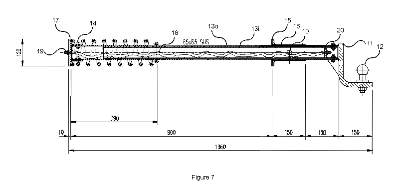
a locking mechanism for locking the tow hitch assembly in a standard
configuration wherein the sliding
member is locked relative to the sleeve and wherein, when the locking
mechanism is unlocked, the
tow hitch assembly assumes a recovery configuration wherein the sliding member
is able to slide with
respect to the sleeve and wherein tow pulling force applied to the hitch
fastener pulls the sliding
member from the sleeve to compress the compression member between the stop and
the sleeve.
[13] The compression member may comprise a non-compressed length and
wherein, in the
standard configuration, the non-compressed length may be configured to leave a
gap between the
distal end of the compression member and the sleeve.
[14] The gap may be at greater than a radius of a vehicle tyre of a vehicle
for which the tow hitch
assembly may be intended.
[15] The non-compressed length may be greater than 350 mm and wherein, in
the standard
configuration, greater than approximately 900 mm of the elongate sliding
member may be located
proximal the sleeve.
[16] The gap may be greater than 400 mm.
[17] The gap may be greater than 500 mm.
[18] In the recovery configurations, the tow hitch faster may be able to
travel greater than 700
mm.
[19] The sleeve may comprise a proximal flange.
[20] The hitch fastener may comprise a right angle mounted tow ball.
[21] The compression member may comprise a compression spring wrapped
around the elongate
sliding member.
[22] The compression spring may be fastened to a proximal region of the
compression member.
[23] The locking mechanism may comprise a peg and aperture arrangement and
wherein the
aperture arrangement may comprise the sleeve and the elongate sliding member
comprising
respective apertures which collocate at a retracted position of the elongate
sliding member.
2
CA 03033114 2019-02-06
WO 2018/027277
PCT/AU2017/050849
[24] The elongate sliding member may be telescopic and comprising outer and
inner telescopic
members and a travel limitation mechanism operative between the outer and
inner telescopic
members configured for limiting the travel of the inner telescopic member with
respect to the outer
telescopic member.
[25] The travel limitation mechanism may comprise an interior inelastic
cord.
[26] In the recovery configuration, the hitch fastener may be able to
travel greater than 1500 mm.
[27] The locking mechanism may comprise a peg and aperture arrangement and
wherein the
aperture arrangement may comprise the sleeve and each of the telescopic
members comprising
respective apertures which collocate at retracted positions of the telescopic
members.
[28] Other aspects of the invention are also disclosed.
Brief Description of the Drawings
[29] Notwithstanding any other forms which may fall within the scope of the
present invention,
preferred embodiments of the disclosure will now be described, by way of
example only, with
reference to the accompanying drawings in which:
[30] Figure 1 shows a vehicle-bourne recovery tow hitch assembly in
accordance with an
embodiment;
[31] Figure 2 shows a trailer-bourne recovery tow hitch assembly in
accordance with a further
embodiment;
[32] Figure 3 illustrates the standard and recovery configurations of the
tow hitch assembly;
[33] Figure 4 illustrates the freeing of vehicle wheels independent of
those of the trailer;
[34] Figure 5 shows a specific vehicle-bourne recovery tow hitch assembly
in accordance with an
embodiment in the standard configuration;
[35] Figure 6 shows the recovery tow hitch assembly of Figure 5 in the
recovery configuration;
[36] Figures 7 and 8 show respective standard and recovery configurations
of a further extendable
recovery tow hitch assembly having greater reach on account of a telescopic
elongate sliding member
arrangement in accordance with an embodiment.
Description of Embodiments
[37] Figure 1 shows an exemplary recovery tow hitch assembly 1 in
accordance with an
embodiment. As can be seen, the tow hitch assembly 1 is utilised between a
vehicle 2 and a trailer 3
each of which may be of differing types within the purposive scope of the
embodiments described
herein.
3
CA 03033114 2019-02-06
WO 2018/027277 PCT/AU2017/050849
[38] The tow hitch assembly 1 comprises an elongate sliding member 13
slidably retained within a
vehicle affixed sleeve 16. The sliding member 13 has a hitch fastener 12 at a
distal end thereof and a
stop 17 at an opposite proximal end (i.e. proximal the vehicle) thereof.
[39] For illustrative convenience, "proximal", as used herein, describes
towards the vehicle and
"distal" refers to towards the trailer.
[40] Furthermore, the tow hitch assembly 1 comprises a compression member
14 operative
between the stop 17 and the sleeve 16.
[41] The tow hitch assembly 1 further comprises a locking mechanism 10 for
locking the tow hitch
assembly in a standard configuration wherein the sliding member 13 is locked
relative to the sleeve
16.
[42] When the locking mechanism 10 is unlocked, the tow hitch assembly
assumes a recovery
configuration wherein the sliding member 13 is free to slide with respect to
the sleeve 16
[43] In the recovery configuration, tow pulling force applied to the hitch
fastener 12 pulls the
sliding member 13 from the sleeve 16 until the compression member 14 is
compressed between the
stop 17 and the sleeve 16.
[44] Figure 2 shows a further embodiment wherein the tow hitch assembly 1
is trailer-bourne. In
a similar manner, the tow hitch assembly 1 in accordance with this embodiment
comprises a trailer-
bourne sleeve 16 within which the elongate sliding member 13 slides. The
trailer born embodiment
of figure 2 may be utilised specifically for trailer types routinely utilised
in bogging prone
environments, such as surf boat trailers and the like allowing for utilisation
of conventional vehicle
tow hitches.
[45] Figure 3 exemplifies the standard and recovery configurations of the
tow hitch assembly 1.
The embodiment shown in figure 3 shows the trailer-borne configuration but it
should be appreciated
that these configurations are equally applicable to the vehicle-bourne
configuration as is substantially
shown in figure 1.
[46] Figure 3A shows the tow hitch assembly 1 in the standard configuration
wherein the elongate
sliding member 13 is locked with respect to the sleeve utilising the locking
mechanism 10. The locking
mechanism 10 shown in figure 3 may comprise a peg and aperture arrangement.
The aperture
arrangement may comprise corresponding overlapping apertures within the sleeve
16 and the
elongate sliding member 13 through which the peg may be inserted at discrete
offsets of the sliding
member 13 with respect to the sleeve 16. In the embodiment shown in figure 3,
a plurality of apertures
are shown so as to allow the locking mechanism to lock the sliding member 13
with respect to the
sleeve 16 at a plurality of offsets. However, in embodiments, the locking
mechanism 10 may be
configured for locking the elongate sliding member 13 with respect to the
sleeve 16 at one position
4
CA 03033114 2019-02-06
WO 2018/027277 PCT/AU2017/050849
wherein, where the locking mechanism 10 comprises a peg and aperture
arrangement, a single
aperture would be provided through both the sleeve 16 and the elongate sliding
member 13.
[47] As such, in the standard configuration as a substantially shown in
figure 3A, the tow hitch
assembly 1 may be utilised as a normal conventional tow hitch assembly.
[48] However, when requiring bogged vehicle/trailer recovery, the
configuration of figure 38 may
be utilised. Specifically, the trailer 3 may be towed by the vehicle 2 in the
standard configuration as is
shown in figure 3A but, when becoming bogged, the locking mechanism 10 may be
released.
[49] As can be seen, and as alluded to above, the release of the locking
mechanism 10 allows the
elongate sliding member 13 to slide with respect to the sleeve 16.
[50] As such, the vehicle 2 may be then driven initially without the
pulling force of the trailer 2,
advantageously assisting the freeing of the vehicle wheels until such time
that the compression
member 14 becomes operative between the stop 17 under sleeve 16 at which time
gradually
increasing force is applied to the trailer 3. As can be appreciated, the
trailer wheel 3 may be freed
both under the effects of the inertia of the vehicle 2 and the potential
energy stored within the
compression member 14.
[51] Ideally, in the standard configuration as is shown in figure 3A, the
compression member 14
leaves a gap 9 between the compression member 14 and the sleeve 16 such that
the compression
member 14 only applies force once the vehicle tyres have become substantially
freed from their
respective depressions. In other words, the gap 9 allows sufficient travel so
as to allow the vehicle
wheels to substantially freed themselves prior force being exerted by the
trailer 3.
[52] In alternative embodiments, as opposed to relying on the gap 9 for
such purpose, the
resilience of the compression member may be configured such that the forces
applied thereby only
become significant once the vehicle wheels have become freed. In other words,
the compression
member 14 may extend further along the proximal portion of the elongate
sliding member 13 to the
sleeve 16, including, in one embodiment, leaving no gap, but, wherein, the
compressive resilience of
the compression member 14 only becomes significant at an extension beyond
which the vehicle is
free.
[53] Figure 4 illustrates the ability to free the vehicle wheels 2 prior
application of towing force
from the trailer 3.
[54] Figure 4A shows a scenario when both the vehicle wheels 2 and the
trailer wheels 3 have
become bogged in sand.
[55] As such, by unlocking the locking mechanism 10, the vehicle 2 is able
to be driven forwards as
is substantially shown in figure 48 devoid of trailer pulling force.
CA 03033114 2019-02-06
WO 2018/027277
PCT/AU2017/050849
[56] As alluded to above, ideally the gap 9 is sufficient so as to allow
the vehicle wheels 2 to travel
a distance of greater than the radius of the vehicle wheels 2 so as to allow
the vehicle wheels 2 to
escape the depression prior the compression member 14 exerting force on the
sleeve 16.
[57] Figure 4C shows a scenario when force is applied by the compression
member 14 on the sleeve
16 which is then able to pull the trailer wheels 3 from the depression after
the vehicle wheels 2 have
been freed. As alluded to above, the pulling force on the trailer 3 may
comprise both a vehicle inertial
and potential energy component thereby advantageously assisting the freeing of
the trailer 3.
[58] Figures 5 and 6 show a specific embodiment of the tow hitch assembly 1
in accordance with
the vehicle-bourne embodiment.
[59] As can be seen, the tow hitch assembly 1 comprises the vehicle affixed
sleeve 16 through
which the elongate sliding member 13 is able to slide.
[60] Figure 5 shows the tow hitch assembly 1 in the standard configuration
wherein the locking
mechanism 10 is locked such that the sliding member 13 is fixed with respect
to the sleeve 16.
[61] Conversely, figure 6 shows the tow hitch assembly in the recovery
configurations wherein the
locking mechanism 10 is unlocked such that the sliding member 13 is able to
slide through the sleeve
16.
[62] Returning to figure 5, the elongate sliding member 13 may take the
form of a 65 x 65 mm
square bar and wherein the sleeve 16 similarly defines a corresponding square
aperture for
accommodating the square bar 13.
[63] Teflon or other friction reducing material such as a plastic sleeve or
the like may be located
on the inner surface of the sleeve 16 so as to facilitate the sliding of the
sliding member 13
therethrough.
[64] The distal end of the sliding member 13 may comprise the hitch
fastener which, in the
embodiment comprises a conventional tow ball 12 affixed to a right angled
bracket 11. Other types of
fasteners or envisaged within the purposive scope of the embodiments provided
herein however.
[65] The proximal end of the elongate sliding member 13 comprises the stop
17, which, in
accordance with this embodiment, comprises a plate 17.
[66] As can be appreciated, in the standard configuration figure 4, the
elongate sliding member 13
is located under the rear of the vehicle with the hitch fastener 12 extending
from beyond the rear of
the vehicle.
[67] In accordance with this embodiment, the compression member 14
comprises a compression
spring 14 which locates around a proximal portion of the elongate sliding
member 13.
[68] The compression member spring 14 may be held at the proximal end of
the elongate sliding
member 13 by way of a spring fastener 18.
6
CA 03033114 2019-02-06
WO 2018/027277
PCT/AU2017/050849
[69] As is also shown, when in the standard configuration, in a preferred
embodiment, the
compression member spring 14 leaves a spacing gap 9 between the compression
member 14 and the
sleeve 16 so as to allow the freeing of the vehicle wheels firstly in the
manner described above with
reference to figure 4. As alluded to above, the spacing gap 9 may be
approximately greater than the
radius of the vehicle wheels. As such, differing spacing gaps 9 may be
configured depending on the
type of vehicle, vehicle wheels and the like.
[70] As is also shown in figure 4, the proximal end of the sleeve 16 may
similarly comprise a flange
15 against which the distal end of the compression member spring 14 abuts.
[71] As is shown in figure 5, in the recovery configuration, when the
locking mechanism 10 has
been unlocked, force applied to the hitch fastener 12 of the tow hitch
assembly 1 allows the elongate
sliding member 13 to slide from the sleeve 16 until such time that the
compression member spring 14
may be fully compressed between the stop 17 and the flange 15 of the sleeve
16.
[72] When fully compressed in this manner, in certain situations, an
inertial jerk may be applied to
the tow hitch assembly 12 which jerks the trailer 3 from the depression and
wherein the potential
energy stored within the compression member 14 further assists in the freeing
of the trailer 3 wheels.
[73] For the embodiment shown in figures 5 and 6, it is envisaged that the
hitch fastener 12 may
travel up to approximately 800 mm (or 778 mm in one specific embodiment).
[74] Furthermore, in the particular embodiment shown in figure 5, the
compression member 14
may have a non-compressible length of approximately 390 mm and wherein, in the
standard
configuration, the elongate sliding member 13 has a proximal length of
approximately 900 mm
between the stop plate 17 and the flange 15, thereby leaving a gap of
approximately 510 mm.
[75] For example, 31" 4x4 tyres may have a radius of 394 mm, being less
than the gap of 510 mm.
[76] Furthermore, in the embodiment shown, the sleeve 16 may comprise a
length of
approximately 150 mm and wherein, in the standard configuration, approximately
150 mm of the
elongate sliding member 13 may be exposed from the distal end of the sleeve
16.
[77] In embodiments, the various dimensions provided herein may be modified
according to
differing applications, vehicle sizes, trailer sizes, load sizes and the like.
[78] Figure 7 and 8 show an embodiment of the tow hitch assembly 1 having a
greater hitch
fastener 12 displacement.
[79] Specifically, in accordance with this embodiment, the hitch faster 12
may travel up to
approximately 1600 mm (1628 mm on one specific embodiment). In alternative
embodiments, the
telescopic arrangement may be utilised to address space limitations under the
rear of the vehicle 2
and have a lesser displacement.
7
CA 03033114 2019-02-06
WO 2018/027277 PCT/AU2017/050849
[80] Such is achieved by the elongate sliding member 13 being telescopic.
Specifically, as can be
seen, the elongate sliding member 13 comprises an outer telescopic member 130
and an inner
telescopic member 13i being telescopically arranged.
[81] The displacement of the inner telescopic member 13i may be limited
with respect to the outer
telescopic member 130 utilising a travel limitation mechanism.
[82] In the embodiment shown in figures 7 and 8, the travel limitation
mechanism comprises an
interior non-elastic cord 18, such as one of sufficient resilience, such as
one being made from winch
cord or cable.
[83] As can be seen, the cord or cable 18 may be fastened between the stop
17 utilising fastener
19 and a corresponding distal fastener plate 20.
[84] In embodiments, the cord 18 may be sheathed or otherwise covered or
protected so as to
reduce fraying, such as adjacent the sleeve 16 on account of the locking
mechanism 10 or the like.
[85] Figure 7 shows when the tow hitch assembly 1 is fully extended and the
cable 18 is taught.
[86] In embodiment, the inner telescopic member 13i maybe distally located
with respect to the
outer telescopic member 130. Furthermore, the interior void of the sleeve 16
may be sufficient so as
to accommodate the outer telescopic member 130.
[87] Furthermore, for this embodiment, where the locking mechanism 10 takes
the form of a peg
and aperture arrangement, collocating apertures may penetrate both the outer
and inner telescopic
members 130, 13i so as to be able to lock both at a desirous retracted
configuration as is a substantially
shown in figure 7.
[88] In embodiments, when recovery is not required, a conventional hitch
fastener 12 may be
fastened directly to the rear stop plate 17.
[89] The foregoing description, for purposes of explanation, used specific
nomenclature to provide
a thorough understanding of the invention. However, it will be apparent to one
skilled in the art that
specific details are not required in order to practice the invention. Thus,
the foregoing descriptions of
specific embodiments of the invention are presented for purposes of
illustration and description. They
are not intended to be exhaustive or to limit the invention to the precise
forms disclosed; obviously,
many modifications and variations are possible in view of the above teachings.
The embodiments were
chosen and described in order to best explain the principles of the invention
and its practical
applications, they thereby enable others skilled in the art to best utilize
the invention and various
embodiments with various modifications as are suited to the particular use
contemplated. It is
intended that the following claims and their equivalents define the scope of
the invention.
8