Note : Les descriptions sont présentées dans la langue officielle dans laquelle elles ont été soumises.
SYSTEM AND METHOD FOR COLLECTING AND UPDATING
GEOGRAPHICAL DATA
[0001] This is a divisional application of Canadian Patent Application
Serial Number
2,875,184, which is a division of Canadian Patent Application Serial Number
2,643,844
which entered the National Phase in Canada on August 26, 2008 based on PCT
international
application no. PCT/US2007/064004, having an international filing date of
March 14,
2007.2,643,844, filed March 14, 2007.
FIELD
[0002] The present disclosure relates generally to collection of data
representative of the
location of utilities and infrastructure in the field for creating a grid and
more particularly for
establishing a record of each transaction during data collection.
BACKGROUND
[0003] Data collection devices typically include a global positioning
system (GPS) unit, a
pole carrying a GPS antenna coupled to the GPS unit, a computer (an input
device, display,
memory and operating software) and power supplies for the GPS unit and the
computer.
[0004] There are also systems presently in use for collecting the
location points of the
infrastructure, including, for example, roads, curbs, property lines, fences,
man-made and
natural elements of an area, and of assets including, for example, utility
lines, archeological
sites and habitats of endangered species. These systems record and/or display
the final result
of the data as collected by the operator. However, there is no record made of
who collected
data, when the data was collected or modified, and how (including what
actions) the operator
arrived at the final result.
- 1 -
CA 3034837 2019-02-22'
[0005] Therefore, there is a need for a system and method for
establishing an improved
and complete record of each transaction of geographical data collection for
utilities.
SUMMARY
[0006] In one embodiment, there is provided a portable electronic device
for utility data
collection including: an antenna; a data collection unit including a locating
pole configured to
detect a radio frequency identification (RFID) or transponder placed on or
near an installed
utility asset and receive data about said installed utility asset from said
RFID or transponder;
and a location determining unit coupled to the data collection unit for
determining a location
of said RFID or transponder and providing location data of the installed
utility asset. The data
collection unit includes: a wireless transceiver for wirelessly communicating
with a remote
server computer; a memory including a starter grid map, and a transaction
table for storing
information about a history of the changes and additions to the received data
about said
installed utility asset, a password, and a name of an operator of the portable
electronic device;
and a processor coupled to the coupled to the wireless transceiver and the
location
determining unit for creating a data record for the installed utility asset,
the data record
including information about the type and location of the installed utility
asset, and
information about time and date of the collected data. The processor is caused
to select an
area from the stored starter grid map; transmit, via the wireless transceiver,
the data record
and the selected area to the remote server computer; receive a latest grid map
from the
remote server computer for the area selected the stored starter grid map, and
generate a
moving map including a representation of the installed utility asset from the
data record and
the received latest grid map. The data collection unit further includes: a
display screen
controlled by the processor for displaying the location data of the installed
utility asset on
said moving map as the portable electronic device is being moved.
[0007] The portable electronic device may be one or more of the group
comprising a
mobile phone, a laptop computer, and a personal digital assistant (PDA).
[0008] The location determining unit may include a global positioning
system (GPS).
- 2 -
Date recu/Date received 2020-06-16
[0009] The processor may be configured to generate a warning signal
based on the
location data of the installed utility asset, a location and movement
direction of the portable
device, and a distance of the portable device to the installed utility asset.
[0009a] The portable device may be installed on a ground breaking equipment.
10009b] The data about the installed utility asset may include information
about one or
more of area, points, lines, and meta data.
[0009c] The data record may further include information about topography of
the selected
area, a manner of collecting the data, information about the topography
integrated into a
Geographic Information System (GIS) data transaction.
[0009d] The data collection unit may be configured to wirelessly receive data
about the
installed utility asset from a remote computer.
[0009e] The processor may be configured to cause the display screen to display
the
location data of the installed utility asset on said grid map, in a
predetermined project area.
- 3 -
Date recu/Date received 2020-06-16
BRIEF DESCRIPTION OF THE DRAWINGS
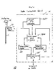
[0010] FIG. 1 is an exemplary block diagram of a data collection unit
used in the field, in
accordance with one embodiment;
[0011] FIG. 2 is an exemplary block diagram of a server, in accordance
with one
embodiment;
[0012] FIG. 3 is an exemplary flow chart of the steps employed by an
operator using a
data collection unit in the field, in accordance with one embodiment;
[0013] FIG. 4 is an exemplary flow chart of a process performed by a
server during the
collection of data in the field, in accordance with one embodiment;
[0014] FIG. 5 shows an exemplary GIS data transaction record, in accordance
with one
embodiment;
[0015] FIG. 6 depicts an exemplary Portal supporting damage prevention
services
utilizing GIS data transaction records, in accordance with one embodiment; and
[0016] FIG. 7 is an exemplary display utilizing GIS data transaction
records in a damage
prevention system.
DETAILED DESCRIPTION
[0017] In one embodiment, there is provided a system and method for
collecting and
recording data representative of the location, and characteristics of
utilities and infrastructure
in the field for creating a grid.
[0018] A record of the transactions by an operator in the field during
data collection may
be useful to a project manager to observe the progress of a project or to
observe the conduct
of the operator. Further, such information may be useful if there is an
accident in the area that
is covered by the map. One type of accident that has occurred in the past is
the accidental
- 4 -
CA 3034837 2019-02-22
contact or fracturing of a utility line such as a gas line or a communication,
fiber optic line. It
will be useful to know if the utility line was properly located on the
topography or map in use
or whether it had one time been deleted from the map or moved on the map and
who was
responsible for the revisions. Thus, to provide a data transaction record for
use during the
collection of the data or as a historical record, a transaction table is
provided in the field data
collection equipment and in the central office data storage unit or server. If
at any time it is
necessary to determine the status of a map, as it existed at a particular
time, and/or the nature
of the changes made, and/or by whom and when the changes were made, the
information is
available in the transaction table at the server, which can also be
communicated to a field
operator using a hand-held or portable computer.
[0019] A geographical information system (GIS) folinat is selected on the
basis of the
subsequent use of the data by a damage control unit. In addition to the
information
concerning the asset or utility, it is often times desirable to have the
infrastructure, such as
roads, fences, waterways, and so forth, that are in the area mapped on a
display that is being
used for displaying the location of the assets. A location of the
infrastructure in the GIS data
should be as precise as the location of the utilities from the asset location
data.
[0020] One embodiment includes a data collection unit. An exemplary block
diagram of
a data collection unit 10 that may be used in the field is shown in FIG. 1.
The data collection
unit 10 includes a locating pole 11, which is placed on top of or next to the
item that is to be
identified and its location placed in the grid or map. The item is typically a
utility line or a
component of the line or some part of the infrastructure in the area where the
data is being
collected.
[0021] The collection unit may further include an antenna 12 on top of
the pole that is
coupled to a location determining system (LDS) 13, such as a GPS unit. The
antenna 12 and
LDS unit 13 provide the longitudinal and latitudinal coordinates of the
element under or next
to the end of the pole 11. The coordinate position of the clement at the
output of the LDS unit
13 is coupled to a computer 14. The coordinate location is input to a
processor 19 in the
- 5 -
CA 3034837 2019-02-22
computer 14. The coordinate location is also applied to a display 17 and is
visible to the user
of the data collection unit.
[0022] In one embodiment, the computer 14 includes an input unit 16 and a
display 17
which are shown combined in FIG. 1. The input unit 16 is typically separate
from the display
17. The computer 14 also includes a processor 19 and a memory 20 that may
include a
library (shown combined in FIG. 1). Typically the library memory is included
inside the
computer 14. The processor 19 also includes memory for the operating system of
the
computer and the software that is being used by the computer. The computer 14
further
includes a transaction table 22, a starter grid map unit 23 that may be stored
in the memory
and a communication unit 25 for communicating, for example, wireles sly with a
server. The
computer 14 may be a Personal Computer (PC), a lap top computer, a personal
digital
assistant (PDA), a mobile phone, or the like.
[0023] The information or data in the field gathered by the data
collection unit 10 is sent
to a server either by wireless or wired connection. An example of such a
server is shown in
FIG. 2. The information in the data collection unit may be lost or misplaced
while the
information stored in the server provides a permanent record of the
information gathered by a
data collection unit.
[0024] The server, as shown in FIG. 2, includes a processor 31 and memory
or storage
device 32. The server also includes a transaction table 33, a latest grid map
unit 35 and a
communication unit 36 for communicating with the communication unit of a data
collection
unit similar to the data collection unit 10 in FIG. 1.
[0025] The data or information collected in the field is transferred to
the server for
updating the asset location and infrastructure location for the specific area
where the data
collection unit is employed. The operator of a data collection unit in the
field may change the
location, description or existence of any utility line or component of a
utility line or any
element of the infrastructure or add data concerning the same during operation
in the field.
These changes or additions result in a new grid map for the area of concern.
To provide a
- 6 -
CA 3034837 2019-02-22
history of the changes and additions, a transaction table 22 is provided in
the data collection
unit and a transaction table 33 is provided in the server unit 30.
[0026] In one embodiment, a database may be used for damage prevention,
data
collection and asset management operations. For example, asset management
operations may
include using a facility file or similar information to identify, characterize
or track an asset.
In addition, various information products may be defined as discussed herein.
[0027] A system and method for collecting, storing and using data in the
form of a grid
map is disclosed in PCT Application PCT/US2005/025724 and in U.S. Patent
Serial Number
7,482,973.
[0028] In one embodiment, asset (e.g., utility) location data may be
created to record a
utility line being placed in the earth. A record of this location is based on
latitudinal and
longitudinal coordinates that are stored for later use. A LDS provides the
latitudinal and
longitudinal coordinates for an asset position recorder while the utility line
is being placed in
the ground.
[0029] Another approach for creating a permanent record of the precise
location of
assets, such as underground utility lines, is placing RFIDs or transponders on
the utility line
as it is being placed in the ground. Thereafter, when the location of the
utility line is to be
recorded, an RFID Reader is moved along the ground to locate the RFIDs that
are on the
utility line. Other types of information, such as the type of the asset
(utility), the size,
manufacturer, the date of placement, date of future service, location based on
one or more
coordinates, owner of the utility, etc may be recorded with the RFID and
subsequently read
and used by the RFID Reader.
[0030] As the RFIDs are read, the position of the RFIDs, and therefore
the utility line, is
recorded by the use of an asset position recorder and optionally, also by a
LDS that is
coupled to the recorder. In one embodiment, the output of the asset position
recorder is an
ASCII stream having fields for the latitudinal coordinates, longitudinal
coordinates and the
identification of the underground asset, and the like.
- 7 -
'CA 3034837 2019-02-22
[0031] Some embodiments are capable of recalling and revising the
collected data using
Precision Integration (PI). In some embodiments, PI is a methodology, process
and
technology used to assure that data points at each step of the information
product
development are captured and integrated into the information product in a
manner that
produces accurate and complete location data.
[0032] Some embodiments PI involves the use of an X, Y coordinate, and
sometimes also
a Z coordinate (e.g., altitude or depth). A accuracy of the signal having the
X, Y (and Z)
coordinates may be provided in collecting utility location data and in
creating a GIS database,
called a PI Landbase, that are combined in various steps of the system to
provide a PI Grid.
In some embodiments PI also involves the use of the location signal in
creating a movable
map that is displayed to show the accurate position of the data collection or
data usage device
and the user in relation to the PI Landbase. Some embodiments also provide for
the accurate
recall of the information based on the generation of data using LDS
technologies, such as
GPS that provide absolute, as opposed to relative, position data. Utility
location information
may be recalled anywhere, anytime in the world with the above mentioned system
and
method.
[0033] Referring now to FIGs. 3 and 4, an exemplary operation of a data
collection unit
communicating with a server is shown in the exemplary flow charts. An operator
authorized
to use the grid map from a server for a selected area first logs onto the
server (30) as shown
in FIG. 3. The operator inputs an identity, which may include a password and
name of the
operator, and the date and time, as shown in block 402. This information is
recorded in a
transaction table (block 406) and is then sent to the server, as shown in
block 408. As shown
in FIG. 4, the server receives (and stores 504) the information an d verifies
the right to
access, in block 502. If the operator is entitled to access the server then
the granting of the
access is sent to the field unit, in block 506. As shown in FIG. 3, the access
being granted is
received from the server at the field unit and the operator then selects the
area grid map that
is to be used in the field, in block 410. At any time, the area grid map and
the actions of the
operator in the field may be viewed on a display as shown in blocks 404, 412,
418, 428, and
- 8 -
CA 3034837 2019-02-22
438. The selection of the grid map for the area is recorded in the transaction
table in block
414. The selected area grid map information is then sent to the server in
block 416.
[0034] The information from the field is received in the server, as shown
in block 508 of
FIG. 4, and the request for the area grid map is stored in the transaction
table at the server, in
block 510. The server then selects and sends the requested area grid map to
the field unit in
block 512. As shown in block 418 of FIG. 3, the selected area grid map in its
latest version is
received at the field unit from the server. This area grid map is displayed
for viewing on the
display in block 420. The receipt of the latest area grid map is recorded in
the transaction
table in block 422 and acknowledgement of the receipt is sent to the server
from the field
unit, in block 424. This acknowledgement is received at the server as shown in
block 514 of
FIG. 4 and stored in the transaction table in block 516.
[0035] The operator in the field is now ready to work with the area grid
map (or
topography data). The operator can now locate an asset, element, or utility in
the grid map, as
shown in block 426 and view the information (block 428). In block 430, the
operator may
perform actions such as adding, deleting or modifying assets, their locations,
types,
infrastructure and their location on the grid map. These actions or activities
are then recorded
in the transaction table in block 432. Each change to the grid map is recorded
in the
transaction table by specifying who, when, what, where, how, and the type of
actions
performed on the grid map. This information is then sent to the server as
shown in block 434.
Each action by the operator or activity of the operator is received at the
server (block 518)
and recorded in the transaction table at the server, as shown in block 520.
[0036] Finally, when the operator logs off (block 436), records and sends
the latest area
grid map to the server (blocks 440 and 442), the latest area grid map is
received from the
field by the server (block 522) and is stored in the transaction table (block
524) and storage
(block 526), at the server.
[0037] FIG. 5 shows an exemplary GIS data transaction record, according
to one
embodiment of the invention. As shown, the GIS data transaction record 50
includes a
Transaction ID field 51 (record), a WHO field (record) 52, a WHEN field
(record) 53, a
- 9 -
CA 3034837 2019-02-22
WHAT field (record) 54, a WHERE field (record) 55, a HOW field (record) 56,
and an
ACTION field (record) 57. The Transaction ID field 51 include the
identification of the
transaction. The WHO field 52 may include user information, information about
the data
collection device, and the LDS, for example the ID of the device and the ID of
a GPS unit.
The WHEN field 53 may include different times associated with the transaction
and the
collected data, for example, server time, client (device) time, satellite
time, and the like. The
WHAT field 54 may include areas such as a particular subdivision in a
particular county,
points such as rocks, valves, topographical points of the areas, and any thing
else that can be
represented by a point. The WHAT field 54 may also include lines, such as
cables, pipelines,
gas lines, sewage lines, and the like. Additionally, the WHAT field 54 may
include meta data
related to the points and lines, such as color, manufacturer, size, age,
serial numbers, etc. of
the valves, cables, pipelines, and others.
[0038] The WHERE field 55 may include location data from different
coordinates
systems, such as satellite coordinate system, x, y, z datums, projection data,
and the like. The
HOW field 56 may include the type of the LDS, such as the type of the GPS
device, laser
range finder device, or RFIDs; the type of the data collection device, such as
PC, lap top,
PDA; and the like. The ACTION field 57 may include the actions that the
operator(s) has
taken, for example, add, modify, delete, copy, send, etc.
[0039] The GIS data transaction record can then be used to generate a
precision
integrated grid. The precision integrated grid is used to identify and locate
a utility in the
region. The information can then be used to warn, for example, a ground
breaking project of
the location of above or below ground utilities. Striking or breaking a
utility can be of such
consequence that tools and methods associated with this task must be of high
reliability.
Some embodiments generate enhanced utility location data sets that meet usage
criteria that
are set by project managers responsible for utility asset management and/or
damage
prevention on a project. In some embodiments a project manager may set forth
and document
accuracy, completeness, currency and utility type visibility criteria and
requirements for the
data sets to be used for the specific project, based on the related GIS data
transactions. For
example, a project may require a SUE engineering, a Standard for locating
underground
- 10 -
CA 3034837 2019-02-22
utilities. A GIS data transaction record may, thus be created that meets the
criteria set by the
project manager. The completed GIS data transaction may be designated a PI
Grid when it
meets the project usage criteria set by the project manager.
[0040] In some instances, a PI Grid is used by project managers for
utility asset
management and utility damage prevention. Data integrity requirements differ
from project
to project. The PI Grid may be designed to support a higher level data
integrity requirement,
for example, damage prevention. By supporting the higher level of data
integrity
requirement, value added services may be provided for the remainder of utility
asset
management projects that have lesser standards for data integrity. In most
damage prevention
scenarios, there is a requirement for using ground breaking equipment in areas
where conflict
with utilities is probable.
[0041] FIG. 6 depicts an exemplary Portal supporting damage prevention
services
utilizing GIS data transaction records from different owners, according to one
embodiment.
As shown, each user-company/organization (user), utilizes the system to create
a GIS data
transaction record. A group of GIS data transaction records is called a Damage
Prevention
Dataset (DPD) hereinafter. In one embodiment, each of these sets of
transaction records is
combined to create a composite PI grid of a particular area that includes DPD
from each
contributing data source (user/owner). Each user implements an agreed to and
coordinated PI
process, as described above. As a member of a cooperative effort, each user's
PI process is
reviewed and coordinated with the other cooperative users. The PI process
includes business
rules and criteria and technology processes that result in the creation of and
provisioning of a
DPD. In one embodiment, the DPD is described by a technical data specification
or
description and is developed from a specific definition of GIS data in which
the GIS layers,
data, attributes, coordinate and positional and currency of data of the DPD is
described. In
one embodiment, the DPD is a subset of user data that is provided for public
usage for the
specific purpose of supporting damage prevention and avoidance within the
prescribed
Damage Prevention Operations Theatre (DPOT). The DPOT is the geographical area
that is
covered by or serviced by DPD data or the area in which Damage Prevention
services are
provided.
- 11 -
CCA 3034837 2019-02-22
[0042] In one embodiment, the integrity, pedigree, correctness, currency
and location
accuracy of the DPD is the responsibility of the user and is described or
pedigreed by the PI
process. The user certifies the pedigree of the data meaning that the user
describes the data in
terms of source, accuracy and currency. A user may provide a highly accurate,
up to date
DPD, while another may provide one that is not as accurate or up to date. The
pedigree of the
DPD provided is clearly described and liability disclaimers concerning the use
of the data are
based on the defined criteria described in the PI process.
[0043] The ONECALLTM block represents the function performed by ONECALLTM
centers that act as a central clearinghouse for marking of utilities in areas
where digging will
occur. A user can call ONECALLTM and tell them that the user will be digging,
for example,
at the corner of 7th street and ELM Ave. ONECALLTM then sends a locate ticket
to all utility
companies that may have utilities in that area. The utility companies are then
required to
mark the location of the utilities. A ONECALLTM entity could serve as the
sponsor or
clearing house for a public damage prevention system by utilizing the system
and method
described herein.
[0044] Pedigree is attained utilizing the PI process to create a unique
combination of data
that provides for a Damage Prevention View (DPV) of utility locations in the
field. DPD are
utilized in the Damage Prevention system to provide a DPV of data in the field
focused
around the decision of 'dig or no dig' related to utilities. The pedigree of
the data facilitates
the DPV which is a display of data contextual to utility damage prevention is
presented to the
user (for example, in a digging equipment) in real time to support operational
decision
making. In operation, a field operator can see on his portable display how
recent and how
accurate the data is and where (the source) the data has come from. Based on
this
conveniently displayed data, the field operator can make a dig or no dig
decision related to
.. utilities in the area. The user interface is also designed in such a way to
visually make it
easier for the field operator to make such dig or no dig' decisions. For
example a danger area
or a buffer zone may be displayed in red color and boundary lines, so that the
operator could
easily see that areas that she needs to avoid with respect to the location of
the utilities and her
location in the area.
- 12 -
CCA 3034837 2019-02-22
[0045] One component of the PI process is a data interchange mechanism.
In one
embodiment, this data interchange mechanism is based on Extensible Markup
Language
(XML) that is tailored to the data requirements of the utility damage
prevention function. The
PI Process generates an XML specification, Damage Prevention XML (DPXML), to
enable a
user to easily share data with the Portal. The standard includes all tags and
definitions needed
to pedigree data and to otherwise identify DPD for exposure to the Portal for
public use. The
standard will increase the interoperability of user GIS systems with the
Portal.
[0046] In one embodiment, user organizations expose (make available) DPD
to the
invention's Portal utilizing a Portal GIS Gateway (GGATE). The GGATE is a
combination of
telecommunications connectivity services combined with data mapping capability
of the
invention. In one embodiment, the Portal utilizes BizTalkTm functionality to
implement the
GGATE. The GGATE accepts DPD file updates from various user sources and stores
it in a
particular format called a Precision Integration Facilities File (PIFF). The
timing and update
schedule for DPD file updates to the Portal is a function of the agreed to PI
process entered
into by cooperative user contributors to the system. In effect, the user is
broadcasting a subset
of user GIS data into the public domain by exposing it to the Portal.
[0047] In one embodiment, the Portal implements a next step of the PI
process,
combining PIFF files via a proprietary process to create a PI Grid. The PI
Grid is comprised
of a combination of PIFF data from user sources rendered as a Precision
Landbase.
[0048] In one embodiment, users register with a damage prevention service
provider to
gain access to damage prevention services that are available within the DPOT.
If approved
for access, the users are allowed to download Damage Prevention Software
(DPSW) to their
local computing devices. DPSW provides for real time damage prevention
functionality in
the field and for viewing of relevant PI Grids from the local computing
device.
[0049] In one embodiment, DPSW is installed on computing devices including
desktop
computers, laptop computers, hand held devices, PDA, or mobile phones. If the
computing
device can be attached to a GPS that outputs coordinate data in a National
Marine Electronic
(NMEA) format, the DPSW software will interoperate with GPS coordinate outputs
in
- 13 -
CA 3034837 2019-02-22
"GPSMODE." If the device cannot be used with a GPS, the DPSW will operate in
an
"AUTOMODE." Internet connectivity is required for use of the damage prevention
system in
either case. Internet connection provides real time access to damage
prevention services.
[0050] The DPSW operating in GPSMODE allows the user to travel to an
area of interest
within the DPOT. PI Grids that have DPD relevant to the current GPS position
of the user are
automatically designated by the system and may be accessed or downloaded by
the system
via the Internet connection of the computing device. DPSW operating in GPSMODE
utilizes
designated PI Grids and provides utility Damage Prevention DPFIND (for
example, "Find"
and or "Locate") functionality. DPFIND shows the user the direction and
distance to utilities
that are present on the PI-GRID and provides pedigree data for the utilities
presented,
providing for operational decisions in the field including avoiding utilities
during dig,
marking and designating utilities, contacting user, and planning and other
operational tasks.
[0051] In one embodiment, users with designated security access may use
DPSW in
GPSMODE and develop field data updates and transmit these updates via the
Portal for use
as field validation updates to user GIS data. "Field Data Updates" may also be
used to
integrate with and provide field data updates to one call systems. "Advanced
Services" may
use a Business to Business Gateway (BBGATE) designed to for transfer and
mapping of data
between systems.
[0052] DPSW operating in AUTOMODE may access PI Grids of interest by
selecting
grid areas from a DPOT key map. PI Grids may be accessed and the data in the
grids may be
viewed with access to all services except "DPFIND" but including access to
pedigree of
information on the grid. Users with approved access may download DPSW software
or
access via Web Access (no client software required) PI Grids of interest by
selecting GRID
areas from a DPOT key map. PI Grids may be accessed and the data in the grids
may be
viewed with access to all services except DPFIND but including access to
pedigree of
information on the grid.
[0053] FIG 7 is an exemplary display utilizing GIS data transaction
records in a damage
prevention system, according to one embodiment. In this embodiment, the server
may run
- 14 -
Date recu/Date received 2020-06-16
RTI Connex0, hereinafter "RTI", available from Real Time Innovations Company
of
Sunnyvale California, and provide to the client devices in the field real time
visual location in
the context of a project area topography (map) enhanced with photo imagery of
the project
area, as shown. During utility data gathering the data collector can see where
he is on the
map and verify the locations that he is taking against identifiable landmarks
(e.g., as seen and
as represented on the display), as shown in FIG. 7. During damage prevention
usage real time
visual location and utility "closeness" warning feedback may be provided to an
individual or
to equipment on which the module is placed. Utility information may be
viewable in
reference to imagery of the related or project area, in real time providing
the current position
of equipment or personnel relative to the location of utilities and may be
viewable as the
person or machine moves in any direction.
[0054] The PI Grid designation or Certification may indicate to the
project manager that
the PI Grid meets project criteria for the use of the data in damage
prevention or other utility
asset management applications. The PI Grid may be presented to the user, via a
computer
screen, or a display as a sophisticated, intuitive, project area topography
(map) that provides
utility location information superimposed on imagery of the project area
(e.g., a visual
representation of an overhead view and other indicia). The PI Grid may be
presented as a
movable map that directionally turns with the movement of the person or
equipment to which
the data collection device is attached or carried. For example, as the data
collection device is
moved (changes position) or turns (changes direction) the displayed image may
change
accordingly (e.g., keeping the data collection device in the middle of the
project area and
orientating the project area so that it "faces" the same direction as the
person or equipment).
As a user walks or rides around a project area, the PI Grid, presented in RTI,
may move and
indicate the location of the user (e.g., via a visual representation) within
the project area,
while simultaneously showing the location of utilities (e.g., via a visual
representation)
within user defined utility location buffer areas, as shown in FIG. 7. The
capability of
presenting PI Grid data in this useable, real time mode provides project
managers with real
time utility location data that is accurate and actionable per the operational
requirements of
the project manager.
- 15 -
Date recu/Date received 2020-06-16
[0055] Utilizing a GIS data transaction, a data collection device may show
(in real time)
data points that are collected and symbology and other meta-data attributes
that may be
associated with collected data. The data collection device may provide real
time feedback,
and validation, and by facilitating "eyes on the ground validation" may
significantly increase
data accuracy. Using a GIS data transaction, data collectors may validate
"where they are" in
a project area and validate that the data they are collecting or revising is
the "correct data."
[0056] While specific embodiments have been described and illustrated,
such
embodiments should be considered illustrative of the subject matter described
herein and not
as limiting the claims as construed in accordance with the relevant
jurisprudence.
- 16 -
CA 3034837 2019-02-22!