Note : Les descriptions sont présentées dans la langue officielle dans laquelle elles ont été soumises.
INJECTION DEVICE
Field of the Invention
[0001] The present invention relates generally to an injection device for
dispensing a
medicament, and more particularly to a low-cost, single use injection device.
Background of the Invention
[0002] Various injection devices are known in the art. Many such
injection devices,
however, require medical training for proper use. In addition, many such
injection devices
are expensive. Thus, there is a need to provide a low-cost, intuitive
injection device that can
be properly used by untrained or minimally trained people for self-injection
or injection of
others. For example such a needed device could be used for inoculations in
developing
areas of the world where medical care is difficult to obtain, or for a parent
to inoculate a
child.
Summary of the Invention
[0003] An aspect of the present invention is to provide a low-cost
injection device.
Another aspect of the present invention is to provide an intuitive injection
device that can be
properly used by untrained or minimally trained people for self-injection or
injection of
others.
[0004] The foregoing and/or other aspects of the present invention are
achieved by
providing an injection device, including a base, a sliding body slidably
connected to the
base, a double-ended needle fixed to the sliding body, a biasing member for
proximally
biasing the sliding body with respect to the base, and for retracting the
needle into the
device subsequent to activation of the device, a medicament cartridge for
holding a
medicament, slidably connected to the sliding body, and a stopper slidably
disposed within
the medicament cartridge. The base has a proximal end and a surface disposed
at a distal
1
CA 3037365 2019-03-20
end thereof for contacting a patient's skin. The base also has a first locking
mechanism. The
sliding body has a locking feature and a second locking mechanism. The second
locking
mechanism locks the medicament cartridge relative to the sliding body upon
completion of
displacement of the medicament cartridge relative to the sliding body. The
first locking
mechanism and the locking feature interact to lock the sliding member relative
to the base
subsequent to retraction of the needle into the device.
[0005] The
foregoing and/or other aspects of the present invention are also achieved by
providing an injection device, including a base having a proximal end and a
surface
disposed at a distal end thereof for contacting a patient's skin, the base
comprising a
plurality of angled lips and a plurality of axial ribs, each plurality being
disposed
circumferentially about an interior of the base, a sliding body slidably
connected to the base,
the sliding body comprising a holding rib protruding radially inward and a
plurality of
circumferentially disposed, distally depending, cantilevered legs, each leg
having a pair of
feet circumferentially protruding from a distal end thereof, and a double-
ended needle fixed
to the sliding body. The device also includes a biasing member for proximally
biasing the
sliding body with respect to the base, and for retracting the needle into the
device
subsequent to activation of the device, a medicament cartridge for holding a
medicament,
the medicament cartridge being slidably connected to the sliding body and
having a
cartridge lip protruding radially outward from a distal end thereof, the
cartridge lip being
disposed adjacent to the holding rib prior to activation of the device, and a
stopper slidably
disposed within the medicament cartridge. A force applied to the medicament
cartridge to
displace the cartridge lip distally past the holding lip exceeds a force
applied to the
medicament cartridge to displace the feet distally past the angled lips and
drive the needle
into a patient's skin.
[0006] The foregoing and/or other aspects of the present invention are also
achieved by
providing a method for injecting a medicament in a patient using an injection
device having
a base, a sliding body slidably connected to the base, a double-ended needle
fixed to the
sliding body, a biasing member, a medicament cartridge for holding a
medicament, the
medicament cartridge being slidably connected to the sliding body, and a
stopper slidably
disposed within the medicament cartridge. The method includes pressing the
medicament
cartridge toward the patient's skin/injection site to sequentially distally
displace the sliding
body relative to the base, insert the needle into the patient, and compress
the spring,
2
CA 3037365 2019-03-20
puncture the stopper with the needle to establish fluid communication between
the needle
and the medicament cartridge, and proximally displace the stopper relative to
the
medicament cartridge to eject the medicament from the medicament cartridge.
The method
also includes, subsequent to ejecting the medicament from the medicament
cartridge,
ceasing pressure on the medicament cartridge to sequentially proximally
displace the sliding
body relative to the base to withdraw the needle from the patient due to the
force of the
spring, and lock the sliding member relative to the base to prevent reuse of
the device.
[0007] Additional and/or other aspects and advantages of the present
invention will be
set forth in part in the description that follows and, in part, will be
apparent from the
description, or may be learned by practice of the invention.
Brief Description of the Drawings
[0008] The above and/or other aspects and advantages of embodiments of the
invention
will be more readily appreciated from the following detailed description,
taken in
conjunction with the accompanying drawings, in which:
FIG. 1 is a perspective view of an injection device in accordance with an
embodiment of the present invention;
FIG 2 is a perspective exploded view of the device of FIG. 1;
FIGS. 3 and 4 are perspective views of a base of the device of FIG. 1;
FIGS. 5 and 6 are perspective views of a sliding body of the device of FIG. 1;
FIG. 7 is a cross-sectional view illustrating a pre-activated state of the
device of
FIG. 1; and
FIGS. 8-11 are cross-sectional views illustrating operation of the device of
FIG. 1.
Detailed Description of Exemplary Embodiments
[0009] Reference will now be made in detail to embodiments of the present
invention,
examples of which are illustrated in the accompanying drawings, wherein like
reference
numerals refer to the like elements throughout, The descriptions of these
embodiments
exemplify the present invention by referring to the drawings.
3
CA 3037365 2019-03-20
1
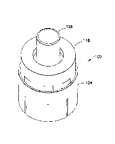
[00101 FIG. 1 is a perspective view of an injection device 100 in
accordance with an
embodiment of the present invention and FIG. 2 is a perspective exploded view
of the
device 100. As shown in FIGS. 1 and 2, the injection device 100 includes a
base 104 that
has a proximal end 108 and a distal end 112, a sliding body slidably connected
to the base
104, a double ended needle 120 fixed to the sliding body 116, and a biasing
member 124
(such as a spring) for proximally biasing the sliding body 116 respect the
base 104 and, as
will be discussed in greater detail below, for retracting the needle 120 into
the device 100
subsequent to activation thereof.
[0011] The device 100 also includes a medicament cartridge 128 for
holding the
medicament., The medicament cartridge 128 is slidably connected to the sliding
body 116.
According to one embodiment, the medicament cartridge 128 is made of glass.
According to
another embodiment, the medicament cartridge 128 is made of a transparent
plastic material
that does not react with the medicament. Examples of such a plastic material
include, but
are not limited to, cyclic olefin polymer (COP) and cyclic olefin copolymer
(COC). One
example of a COC is available from Zeon Chemicals, L.P., of Louisville,
Kentucky under
the designation "BD CCP Resin," and is listed by the U.S. Food and Drug
Administration as
DMF No. 16368.
[0012] In addition, the device includes a stopper 132 slidably disposed
within the
medicament cartridge 128, for retaining the medicament within the medicament
cartridge
128 and expelling the medicament from the medicament cartridge 128. In
combination, the
medicament cartridge 128 and the stopper 132 disposed therein define a
medicament
chamber therebetween. According to one embodiment, the stopper 132 is made of
an
elastomeric material, such as rubber, that does not react with the medicament.
[0013] In one embodiment, the medicament cartridge 128 is pre-assembled to the
remainder of the device 100, and the entire device 100 is provided to the user
in sterile
packaging, for example a cup with a foil top. According to another embodiment,
a pre-filled
medicament cartridge 128 (including the stopper 132) is provided separately
from the
remainder of the device 100. In such an embodiment, the medicament cartridge
128 can be
assembled to the remainder of the device 100 at the time of the injection, and
thus, is,
selectively connectable to the sliding body 116, as described in greater
detail below.
Refrigeration space may be at a premium in developing areas of the world. For
medicament
4
CA 3037365 2019-03-20
that needs to be refrigerated, such a design provides for more efficient use
of the
refrigeration space because only the medicament cartridge 128 is refrigerated,
not the entire
device 100.
[0014] FIGS. 3 and 4 are respective perspective views of proximal and
distal ends 108
and 112 of the base 104. As shown in FIG. 3, the base 104 has a plurality of
angled lips 136
disposed circumferentially about interior of the base 104. Each of the angled
lips 136
projects radially inward, and is angled distally with respect to the base 104.
In addition,
each angled lip 136 has a proximal angled surface 140 and a distal angled
surface 144. The
base 104 also includes a plurality of axial ribs 148 circumferentially
disposed about the
interior of the base 104. The axial ribs 148 are distally separated from the
angled lips 136 to
define a locking space 152 therebetween. According to on embodiment, a pair of
axial ribs
148 corresponds to each angled lip 136 and the individual ribs 148 of the pair
are
circumferentially disposed on opposing sides of the corresponding angled lip
136.
Collectively, the angled lips 136 and the axial ribs 148 (as well as the
locking space 152
disposed therebetween) form a first locking mechanism, which is discussed in
greater detail
below.
[0015] The base 104 additionally includes a central boss 156 with a
central bore 160
through which the needle 120 moves. In addition, as will be described in
greater detail
below, according to one embodiment, the base 104 includes a plurality of base
locking ribs
158 for connecting the sliding body 116 and the base 104 prior to activation
of the device
100.
10016] As shown in FIG. 4, the distal end of the base 112 has a surface
164 for contacting
a patient's skin. According to one embodiment, the surface 164 is flat.
According to another
embodiment, the surface 164 is concave, or proximally domed, for example, to
stably
contact the patient's skin. One skilled in the art will understand that the
surface 164 may be
convex, have another shape, or have a plurality of shapes without departing
from the scope
of the invention. According to one embodiment, at least a portion of the
surface 164 has an
adhesive disposed thereon for temporarily adhering the device 100 to the
patient's skin.
Such an adhesive portion may be covered by, for example, a paper cover which
is removed
prior to use of the device 100.
CA 3037365 2019-03-20
[0017] FIG. 5 is a perspective view of proximal ends of the sliding body
116 and the
needle 120, and FIG. 6 is a perspective view of the distal ends of the sliding
body 116 and
the needle 120. According to one embodiment, the needle 120 is fixed to the
sliding body
116. In other words, the needle 120 does not displace relative to the sliding
body 116.
Methods for fixing the needle 120 to the sliding body 116 include gluing,
epoxying, insert
molding, and swaging, using, for example, heat or ultrasonic energy. One
skilled in the art
will appreciate that other methods of fixing the needle 120 to the sliding
body 116 may be
employed without departing from the scope of the invention.
[0018] As shown in FIGS. 5-7, the sliding body 116 includes a plurality of
circumferentially disposed, distally depending, cantilevered legs 168.
According to one
embodiment, each leg 168 has a pair of feet 172 circumferentially protruding
from a distal
end thereof. According to one embodiment, as shown in FIGS. 5 and 6 (although
most
clearly shown in FIG. 11), proximal surfaces 176 of the feet 172 are angled to
correspond to
the angle of the distal angled surfaces 144 of the angled lips 136.
Collectively, the legs 168
and the feet 172 form a locking feature, which is discussed in greater detail
below.
[0019] To assemble the sliding body 116 with the base 104, first, the
biasing member 124
is inserted into the base 104 around the central boss 156. Subsequently, the
sliding body is
inserted distally into the base 104 (over the biasing member 124) until the
legs 168 and/or
the feet 172 elastically deform radially inward and the feet 172 distally pass
base locking
ribs 158. Subsequently, the legs 168 and/or of the feet 172 spring back
radially outward to
contact the inner wall of the base 104. According to one embodiment, the base
locking ribs
158 are angled to correspond to the angle of the proximal surfaces 176 of the
feet 172.
Because of the corresponding angles, once the feet 172 distally pass the base
locking ribs
158, the base locking ribs 158 engage the proximal surfaces 176 of the feet
172 (due to the
force of the biasing member 124, which biases the sliding body 116 proximally
relative to
the base 104) to prevent proximal movement of the feet 172 past the base
locking ribs 158.
Such an assembled state is shown, for example, in FIG. 7.
[0020] Referring back to FIG. 5, sliding body 116 additionally includes a
central portion
180 that has a stopper-receiving boss 184 centrally disposed thereon. The
walls of the
central portion 180 form a cartridge channel for slidably receiving the
medicament cartridge
128. In addition, as shown in FIG. 6, the central portion 180 has an opening
188 at a distal
6
CA 3037365 2019-03-20
end thereof for receiving the central boss 156 of the base 104 and the biasing
member 124.
Referring to FIGS. 5 and 7, the central portion 180 has a series of ribs
disposed therein,
specifically, a connecting rib 192, a holding rib 196, and a locking rib 200.
As discussed in
greater detail below, the locking rib 200 forms a second locking mechanism.
During
operation of the device 100, the ribs 192, 196, and 200 interact with a
cartridge lip 204,
which protrudes radially outward from the distal end of the medicament
cartridge 128.
According to one embodiment, the ribs 192, 196, and 200 are annular.
[0021] According to another embodiment, the connecting rib 192, for
example, includes
a plurality of connecting ribs 192 circumferentially spaced from each other
about the central
portion 180. In other words, rather than a solid ring, the plurality of
connecting ribs 192 are
disposed to form a segmented array with spaces between the segments. Such an
embodiment may reduce the amount of force necessary to distally advance the
cartridge lip
204 past the connecting ribs 192. For example, if the medicament cartridge 128
is made of
glass, and thus, is relatively inflexible, the reduced force required to
advance the cartridge
lip 204 past the plurality of discrete connecting ribs 192 may be
advantageous. Regardless
of the choice of materials for the medicament cartridge 128, though, one
skilled in the art
will appreciate that various combinations of annular rings and ring segments
may be
respectively used for the ribs 192, 196, and 200 without departing from the
scope of the
invention.
100221 To secure the medicament cartridge 128 to the sliding body 116, a
user inserts the
medicament cartridge 128 into the central portion 180 of the sliding body 116
until the
cartridge lip 204 passes the connecting rib 192 and comes to rest against the
holding rib
196, as shown in FIG. 7. In this pre-activated state, the cartridge lip 204 is
disposed between
the connecting rib hundred 92 and the holding rib 196 and the feet 172 are
disposed
adjacent to the angled lips 136, as shown in FIGS. 7. In this state, the
sliding body 116 is in
a first, or pre-activated position, in which the needle 120 is disposed
entirely within the
device 100. According to one embodiment, the force required to distally
displace the
cartridge lip 204 past the holding lip 196 is greater than the force required
to distally
displace the cartridge lip 204 past the connecting rib 192. Such an embodiment
provides
ease of connection of the medicament cartridge 128 with the sliding body 116
but prevents
inadvertent activation of the device 100 during connection. According to one
embodiment,
the holding rib 196 protrudes radially inward further than the connecting rib
192 to provide
7
CA 3037365 2019-03-20
the force differential. According to another embodiment, the holding rib 196
is less flexible
than the connecting rib 192 to provide the force differential.
[0023] Operation of the device 100 will now be described with respect to
FIGS. 7-11.
After assembling the device 100 (or removing the pre-assembled device 100 from
its
packaging) and using an alcohol swab to disinfect an injection site on the
patient's skin 208,
the user presses the pre-activated device 100 (FIG. 7) against the patient's
skin 208 and
presses down (i.e., distally) on the medicament cartridge 128. The force
required to distally
displace the cartridge lip 204 relative to the holding rib 196 is greater than
the force
required to distally displace the feet 172 relative to the angled lips 136.
Additionally, the
force required to distally displace the cartridge lip 204 relative to the
holding rib 196 is
greater than the force required to compress the biasing member 124 and pierce
the patient's
skin 208 with the distal end of the needle 120. Accordingly, as shown in FIG.
8, when the
user presses down on the medicament cartridge 128, the force is transferred to
the sliding
body 116 and the legs 168 and/or the feet 172 elastically deform radially
inward, thereby
allowing the feet 172 to distally pass the angled lips 136. The legs 168
and/or the feet 172
then snap back radially outward and the slide distally along the axial ribs
148. In addition,
the sliding body 116 compresses the biasing member 124 and drives the needle
120 to a
predetermined depth into the patient's skin 208. In this second, or activated
position of the
sliding body 116, a portion of the needle 120 extends outside of the device
100.
[0024] As the user continues to depress the medicament cartridge 128, the
cartridge lip
204 distally passes the holding rib 196 and the medicament cartridge 128 and
the stopper
travel distally in the cartridge channel, seating the stopper 132 on the
stopper-receiving boss
184. This action also pierces the stopper 132 with the proximal end of the
needle 120,
thereby establishing fluid communication between the medicament and the needle
120, as
shown in FIG 9. Thus, the stopper 132 is selectively pierceable by the needle
120 to
establish communication with the medicament. As the user continues to press
down on the
medicament cartridge 128, as shown in FIG. 10, the medicament cartridge 128
travels
distally in the cartridge channel relative to the stopper 132 and the sliding
body 116, thereby
expelling the medicament from the medicament chamber, through the needle 120,
and into
the patient.
8
CA 3037365 2019-03-20
100251 The locking rib 200 is disposed at the distal end of the cartridge
channel so that
when the medicament cartridge 128 reaches the end of its distal stroke (FIG.
10), the
cartridge lip 204 distally passes the locking rib 200, thereby locking the
medicament
cartridge 128 relative to the sliding body 116. That is, the second locking
mechanism
(locking rib 200) engages the cartridge lip 204 and prevents movement of the
medicament
cartridge 128 with respect to the sliding body 116. Put another way, the
second locking
mechanism locks the medicament cartridge 128 relative to the sliding body 116
upon
completion of the displacement of the medicament cartridge 128 relative to the
sliding body
116. As used herein, locking an element relative to another element prevents
subsequent
relative displacement of the two elements. As additionally shown in FIG. 10,
according to
one embodiment, when the medicament cartridge 128 reaches the end of its
distal stroke,
the proximal surface of the medicament cartridge is substantially planar with
the proximal
surface of the sliding body 116. Such a configuration prevents a user from
gaining a
purchase on the medicament cartridge 128, and thereby prevents an attempt to
proximally
displace the medicament cartridge 128 relative to the sliding body 116.
100261 As shown in FIG. 11, subsequent to the administration of the
medicament to the
patient, the user releases the medicament cartridge 128 and the sliding body
116 (and the
medicament cartridge 128 locked thereto) moves proximally with respect to the
base 104
due to the force of the biasing member 124, thereby withdrawing the needle 120
from the
patient and disposing the needle 120 completely within the device 100. More
specifically, as
the sliding body 116 moves proximally, the feet 172 slide proximally along the
axial ribs
148. Upon passing the proximal ends of the axial ribs 148, the legs 168 and/or
the feet 172
spring back radially outward into the locking spaces 152 and the proximal
surfaces 176 of
the feet 172 engage the distal angled surfaces 144 of the angled lips 136,
thereby locking
the sliding body 116 relative to the base 104. In other words, the distal
angled surface 144
prevents proximal movement of the feet 172 and the proximal ends of the axial
ribs 148
prevent distal movement of the feet 172. Put another way, the first locking
mechanism and
the locking feature interact to lock the sliding member 116 relative to the
base 104
subsequent to retraction of the needle 120 into the device 100. In this third,
or locked
position of the sliding member 116, the needle 120 is again retracted entirely
within the
device 100. The third position of the sliding body 116 is distally displaced
relative to the
first position,
9
CA 3037365 2019-03-20
[0027] Although,only a few exemplary embodiments of the present invention have
been
described in detail above, those skilled in the art will readily appreciate
that many
modifications are possible in the exemplary embodiments without materially
departing from
the novel teachings and advantages of this invention. Accordingly, all such
modifications
are intended to be included within the scope of the appended claims and
equivalents thereof.
CA 3037365 2019-03-20