Note : Les descriptions sont présentées dans la langue officielle dans laquelle elles ont été soumises.
CA 03037676 2019-03-20
WO 2018/057721
PCT/US2017/052695
CONTROL ASSEMBLY FOR A WALK-BEHIND MOWER
CROSS-REFERENCE TO RELATED APPLICATIONS
[0001] This application claims priority to U.S. Provisional Patent
Application Serial
No. 62/397,659 filed September 21, 2016, and entitled CONTROL ASSEMBLY FOR A
WALK-BEHIND MOWER, which is herein incorporated by reference in its entirety.
FIELD OF THE INVENTION
[0002] The present invention relates to walk-behind lawn mowers, and more
particularly, to an all-wheel drive self-propelled lawn mower.
BACKGROUND OF THE INVENTION
[0003] The propulsion of walk-behind lawn mowers has historically been
operator-
powered which required the operator to push the lawn mower around the yard.
More
recent walk-behind mowers have added self-propelled technology that typically
includes
a transmission that is powered by the primary engine, wherein the transmission
is
operatively connected to a pair of opposing wheels of the lawn mower to
provide
rotational power to those wheels so as to drive the mower. Generally, the self-
propelled
transmission is a single-speed transmission that is either engaged/on or
disengaged/off.
These single-speed self-propelled transmissions are typically controlled by an
on/off
switch or lever positioned on or near the cross-bar of the handle. These
switches or
levers may include, for example, a fore-aft adjustable lever on one leg of the
handle, a
rotatable bale that may operate independently or in conjunction with the
safety bale, or a
trigger-like mechanism, wherein actuation of the switches or levers causes the
transmission to become engaged such that the transmission powers the wheels of
the
lawn mower.
[0004] These single-speed self-propelled transmission for a walk-behind
mower are
often difficult to effectively use by an operator for several reasons. For
example, the
speed generated by the transmission to the wheels may cause the lawn mower to
travel at
a speed that can be too fast or too slow for the operator. As such, if the
propelled speed is
too slow, the operator ends up providing the pushing force. On the other hand,
if the
1
CA 03037676 2019-03-20
WO 2018/057721
PCT/US2017/052695
propelled speed is too fast, the operator ends up being dragged along by the
lawn mower.
In either situation, transmission often cannot be optimized for each
individual operator.
Alternatively, when an operator approaches an object such as a tree, house,
sidewalk,
posts, or the like, the operator often desires to slow down to make turns or
navigate the
lawn mower around these obstacles, but the self-propelled transmission being
engaged
causes the lawn mower to proceed at the same speed which can make avoiding
obstacles
more difficult.
BRIEF SUMMARY OF THE INVENTION
[0005] In one aspect of the present invention a control assembly for
controlling a
drive mode of a walk-behind lawn mower is provided. The control assembly
includes a
casing attached to a handle assembly. A first lever is operatively connected
to the casing
and extending from a lateral side of the casing. The first lever is rotatable
between a first
operative position and a second operative position relative to the casing. A
second lever
is operatively connected to the casing and extending from an opposing lateral
side of the
casing than the first lever. The first lever is rotatable between a first
operative position
and a second operative position relative to the casing. A front transmission
is operatively
connected to the first lever and a pair of front wheels, wherein rotation of
the first lever
from the first operative position to the second operative position causes the
front
transmission to be switched from a disengaged state to an engaged state, the
front wheels
being driven by the front transmission when the front transmission is switched
from the
disengaged state to the engaged state. A rear transmission operatively
connected to the
second lever and a pair of rear wheels, wherein rotation of the second lever
from the first
operative position to the second operative position causes the rear
transmission to be
switched from a disengaged state to an engaged state, the rear wheels being
driven by the
rear transmission when the rear transmission is switched from the disengaged
state to the
engaged state. Actuation of both the first lever and the second from the first
operative
position to the second operative position produces an all-wheel-drive mode in
which the
front wheels are driven by the front transmission and the rear wheels are
driven by the
rear transmission. The all-wheel-drive mode is maintained by continuously
actuating
only one of the first lever or the second lever in the second operative
position
2
CA 03037676 2019-03-20
WO 2018/057721
PCT/US2017/052695
[0006] In another aspect of the present invention, control assembly for
controlling a
drive mode of a walk-behind lawn mower is provided. The control assembly
includes a
casing attached to a handle assembly. The casing is formed of an upper housing
and a
lower housing. A first lever is operatively connected to the casing and
extends outwardly
from a lateral side of the casing. The first lever is rotatable between a
first operative
position and a second operative position relative to the casing. A second
lever is
operatively connected to the casing and extends outwardly from an opposing
lateral side
of the casing than the first lever. The first lever is rotatable between a
first operative
position and a second operative position relative to the casing. A plurality
of
transmissions are operatively connected to the first and second levers. The
plurality of
transmissions are operatively connected to the front wheels and the rear
wheels.
Actuation of both the first lever and the second from the first operative
position to the
second operative position produces an all-wheel-drive mode in which the front
wheels
and rear wheels are driven by at least two of the transmissions.
[0007] In still another aspect of the present invention, a control assembly
for
controlling a drive mode of a walk-behind lawn mower is provided. The control
assembly includes a casing attached to a handle assembly. The casing is formed
of an
upper housing and a lower housing. A pair of levers are operatively connected
to the
casing, wherein two of the levers extend in opposite directions from the
casing and the
levers are rotatable relative to the casing between a first operative position
and a second
operative position. A plurality of transmissions are operatively connected to
the first and
second levers, the plurality of transmissions are operatively connected to
front wheels
and rear wheels. The plurality of transmissions generate a no-wheel-drive
mode, a front-
wheel-drive mode, a rear-wheel-drive mode, and an all-wheel-drive mode in
response to
selective rotation of the first and second levers.
[0008] Advantages of the present invention will become more apparent to
those
skilled in the art from the following description of the embodiments of the
invention
which have been shown and described by way of illustration. As will be
realized, the
invention is capable of other and different embodiments, and its details are
capable of
modification in various respects.
3
CA 03037676 2019-03-20
WO 2018/057721
PCT/US2017/052695
BRIEF DESCRIPTION OF SEVERAL VIEWS OF THE DRAWINGS
[0009] These and other features of the present invention, and their
advantages, are
illustrated specifically in embodiments of the invention now to be described,
by way of
example, with reference to the accompanying diagrammatic drawings, in which:
[0010] FIG. 1 is an exemplary embodiment of a self-propelled walk-behind
lawn
mower;
[0011] FIG. 2A is a top perspective view of a control assembly in a no-
wheel-drive
mode;
[0012] FIG. 2B is a cut-away view of the control assembly in a no-wheel-
drive mode,
as shown in FIG. 2A;
[0013] FIG. 3 is an exploded view of an embodiment of the control assembly;
[0014] FIG. 4A is a top view of an embodiment of a first lever;
[0015] FIG. 4B is a bottom view of the first lever shown in FIG. 4A;
[0016] FIG. 5A is a top view of an embodiment of a second lever;
[0017] FIG. 5B is a bottom view of the second lever shown in FIG. 5A;
[0018] FIG. 5C is a top perspective view of the second lever shown in FIG.
5A;
[0019] FIG. 6A is a top perspective view of a control assembly in an all-
wheel-drive
mode;
[0020] FIG. 6B is a cut-away view of the control assembly in an all-wheel-
drive
mode, as shown in FIG. 6A;
[0021] FIG. 7A is a top perspective view of a control assembly in a rear-
wheel-drive
mode;
[0022] FIG. 7B is a cut-away view of the control assembly in an rear-wheel-
drive
mode, as shown in FIG. 7A;
[0023] FIG. 8A is a top perspective view of a control assembly in a front-
wheel-drive
mode;
[0024] FIG. 8B is a cut-away view of the control assembly in a front-wheel-
drive
mode, as shown in FIG. 8A;
[0025] FIG. 9A is a perspective view of an embodiment of a lower housing;
[0026] FIG. 9B is a plan view of the lower housing of FIG. 9A;
[0027] FIG. 10A is a perspective view of an embodiment of an upper housing;
4
CA 03037676 2019-03-20
WO 2018/057721
PCT/US2017/052695
[0028] FIG. 10B is a plan view of the upper housing of FIG. 10A;
[0029] FIG. 11 is a schematic diagram of the connections between the
control
assembly and the front and rear transmissions; and
[0030] FIG. 12 is a schematic diagram of the connections between the front
and rear
transmissions with the power source and the front and rear wheels.
[0031] It should be noted that all the drawings are diagrammatic and not
drawn to
scale. Relative dimensions and proportions of parts of these figures have been
shown
exaggerated or reduced in size for the sake of clarity and convenience in the
drawings.
The same reference numbers are generally used to refer to corresponding or
similar
features in the different embodiments. Accordingly, the drawing(s) and
description are to
be regarded as illustrative in nature and not as restrictive.
DETAILED DESCRIPTION OF THE PREFERRED EMBODIMENT
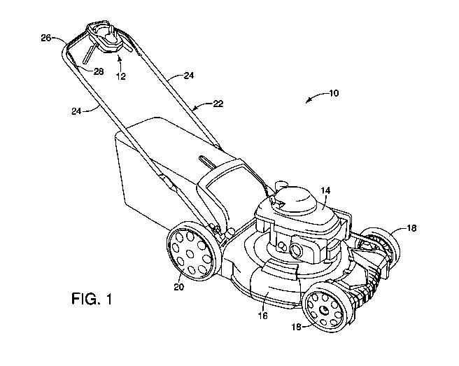
[0032] Referring to FIG. 1, an exemplary embodiment of a self-propelled
walk-
behind lawn mower 10 having a control assembly 12 for selectively controlling
the self-
propulsion of the mower 10 is shown. In the illustrated embodiment, the lawn
mower 10
includes a power source 14 that powers a rotating blade assembly (not shown)
for cutting
grass, and the power source 14 is mounted on a deck 16 or frame that provides
a
structural base for the lawn mower 10. In the illustrated embodiment, the
power source
14 is an internal combustion engine. It should be understood by one having
ordinary skill
in the art that the power source 14 of the mower 10 can alternatively include
an electric
motor or a hybrid-electric power source. A pair of front wheels 18 are
operatively
connected to the deck 16 by way of a front axle, and a pair of rear wheels 20
are
operatively connected to the deck 16 by way of a rear axle. The mower 10
further
includes a front transmission 200 and a rear transmission 210, wherein the
front and rear
transmissions 200, 210 are operatively connected to the front and rear wheels
18, 20 for
providing selective rotation thereof. The control assembly 12 is configured to
independently and selectively switch the front and rear transmissions 200, 210
between
an engaged state and a disengaged state, as will be described below.
[0033] As shown in FIG. 1, the exemplary embodiment of the mower 10
includes a
handle assembly 22 for controlling the direction and movement of the mower 10.
The
CA 03037676 2019-03-20
WO 2018/057721
PCT/US2017/052695
handle assembly 22 includes a pair of generally parallel arms 24 extending
from the deck
16 in a spaced-apart manner and a cross bar 26 that extends laterally between
the pair of
arms 24. It should be understood by one having ordinary skill in the art that
other handle
assembly 22 designs can be used to control the direction of the mower 10. The
mower 10
also includes a safety bale 28 that acts as an operator presence control,
wherein the safety
bale 28 is actuatable between a disengaged position in which the safety bale
28 is spaced
apart from the cross bar 26 and an engaged position in which the safety bale
28 is rotated
to a position in contact with or immediately adjacent to the cross bar 26. The
safety bale
28 acts to ensure that the engine is stopped when the user releases the safety
bale 28.
Actuation of the safety bale 28 to the engaged position allows the operator to
start the
operation of the power source 14, and actuation of the safety bale 28 to the
disengaged
position turns off the power source 14. The safety bale 28 is biased toward
the
disengaged position such that releasing the safety bale 28 causes the safety
bale 28 to
return to the disengaged position. The control assembly 12 is attached to the
cross bar 26
and is configured to be actuated in cooperation with but separately from the
safety bale
28.
[0034] FIGS. 2A-2B and 3 illustrate an exemplary embodiment of the speed
control
assembly 12. The speed control assembly 12 is operatively connected to the
cross bar 24
of the handle 20. In an embodiment, the speed control assembly 12 includes a
casing 31
formed of an upper housing 30 and a lower housing 32 attached to the upper
housing 30.
A portion of the cross bar 26 of the handle assembly 22 is sandwiched between
the upper
and lower housings 30, 32 when attached together. A plurality of attachment
mechanisms 34, such as bolts, screws, or the like, are inserted through
apertures or bosses
formed in the lower housing 32, passing through holes in the cross bar 26, and
received in
corresponding apertures or bosses formed in the upper housing 30 to secure the
upper and
lower housing 30, 32 together while also attaching the entire casing 31 of the
speed
control assembly 12 to the handle assembly 22. The upper and lower housings
30, 32 are
attached to the cross bar 26 in fixed manner such that the casing 31 does not
move or
rotate relative to the cross bar 26.
[0035] In an exemplary embodiment, the control assembly 12 includes a first
lever 38
and a second lever 40, wherein the first and second levers 38, 40 extend from
opposing
6
CA 03037676 2019-03-20
WO 2018/057721
PCT/US2017/052695
sides of the casing 31, as shown in FIGS. 2A-2B and 3. One end of each of the
first and
second levers 38, 40 is rotatably connected to the interior of the casing 31,
which allows
the opposing end of each of the first and second levers 38, 40 to be rotatable
relative to
the casing 31. In an embodiment, the first and second levers 38, 40 are biased
to a first
operative position, as shown in FIG. 2A, wherein the corresponding
transmissions are in
a disengaged state, as will be described below. The first and second levers
38, 40 are
independently and selectively rotatable between the first operative position
and a second
operative position in which the respective lever is positioned immediately
adjacent to the
cross bar 26 of the handle assembly 22. FIGS. 6A-6B illustrate an embodiment
in which
the first and second levers 38, 40 are both rotated to the second operative
position such
that the first and second levers 38, 40 are positioned immediately adjacent to
the cross bar
28 of the handle assembly 22. In an embodiment, the first and second levers
38, 40 are
biased toward the first operative position wherein the corresponding front and
rear
transmissions 200, 210 are in the disengaged state.
[0036] As shown in FIG. 3, the control assembly 12 includes an upper
housing 30, a
lower housing 32, a first lever 38, a first spring latch 42 operatively
connected to the first
lever 38, a second lever 40, a second latch 44 operatively connected to the
second lever
40, and a plurality of attachment mechanisms 34 that operatively connect the
upper and
lower housings 30, 32 together as well as operatively connect the casing 31 to
the cross
bar 26 of the handle assembly 22. The first lever 38 is operatively connected
to the front
transmission 200 (FIG. 11) by way of a first connector 47, wherein actuation
of the first
lever 38 causes the front transmission 200 to become engaged for providing
rotational
power to the front wheels 18. The second lever 40 is operatively connected to
the rear
transmission 210 (FIG. 11) by way of a second connector 49, wherein actuation
of the
second lever 40 causes the rear transmission 210 to become engaged for
providing
rotational power to the rear wheels 20. It should be understood by one having
ordinary
skill in the art that the first lever 38 can alternatively be configured to
operate the rear
transmission 210 and the second lever 40 can be configured to operate the
front
transmission 200. In an embodiment, the first and second connectors 47, 49 are
formed
as Bowden cables.
7
CA 03037676 2019-03-20
WO 2018/057721
PCT/US2017/052695
[0037] An exemplary embodiment of the first lever 38 and the first spring
latch 42 is
shown in FIGS. 4A-4B. The first lever 38 includes a first connecting boss 50
positioned
at a distal end of the first lever 38. The first connecting boss 50 is a
generally cylindrical
member defining a first attachment aperture 52 therethrough. The first
connecting boss
50 is configured to receive the first attachment mechanisms 112, 130 (FIG. 7B)
extending
from either the upper and/or lower housing 30, 32 so as to connect the first
lever 38 to the
casing 31 in a rotatable manner. The first lever 38 is configured to rotate
about first
longitudinal axis 53 that extends through the first attachment aperture 52. A
first central
portion 54 extends from the first connecting boss 50 in a transverse manner
relative to the
first longitudinal axis 53. The first central portion 54 includes an upper
surface 56 and an
opposing lower surface 58. The first central portion 54 is an elongated,
substantially flat
member with a first cut-out 60 formed into a side edge of the first central
portion 54
adjacent to the end of the first central portion 54 opposite the first
connecting boss 50.
The first cut-out 60 is configured to allow the first lever 38 to be fully
rotated into contact
with (or positioned immediately adjacent to) the cross bar 26 of the handle
assembly 22
when the first lever 38 is actuated to the second operative position. When in
the second
operative position, the first cut-out 60 partially surrounds the second
connecting boss 70
of the second lever 40.
[0038] As shown in FIGS. 4A-4B, the first lever 38 further includes a first
biased
member 62 that extends from the outer circumferential surface of the first
connecting
boss 50. The first biased member 62 is substantially aligned with the first
longitudinal
axis 53 and extends from a location below the lower surface 58 to a location
above the
upper surface 56. The first biased member 62 is configured to contact a spring
136
integrally formed with the upper housing 30, wherein the first spring 136
biases the first
lever 38 toward the first operative position, as will be described in more
details below. A
first positioning boss 63 extends in a curved manner tangentially away from
the first
connecting boss 50. The first positioning boss 63 is positioned adjacent to,
and integrally
formed with, the lower surface 58 of the first central portion 54. The first
positioning
boss 63 engages the second spring latch 44, as will be described in more
detail below. A
first cable boss 64 is a cylindrical boss extending from the lower surface 58
of the first
central portion 54, wherein one end of the first connector 47 (FIG. 2B) is
attached to the
8
CA 03037676 2019-03-20
WO 2018/057721
PCT/US2017/052695
first cable boss 64 of the first lever 38. The first lever 38 also includes a
first spring boss
66 positioned immediately adjacent to the first cut-out 60 on the central
portion 54. The
first spring boss 66 extends downwardly from the lower surface 58, and the
first spring
latch 42 is secured to the first spring boss 66. The grip portion 68 extends
from the end
of the first central portion 54 opposite the first connecting boss 50. The
grip portion 68
has a curvature that corresponds to the shape of the cross bar 26 of the
handle assembly
22, which allows the grip portion 68 to abut a portion of the outer rounded
surface of the
cross bar 26 when the first lever 38 is actuated to the second operative
position.
[0039] An exemplary embodiment of the second lever 40 and the second spring
latch
44 is shown in FIGS. 5A-5C. The second lever 40 includes a second connecting
boss 70
positioned at a distal end of the second lever 40. The second connecting boss
70 is a
generally cylindrical member defining a second attachment aperture 72
therethrough.
The second connecting boss 70 is configured to receive the second attachment
mechanisms 114, 132 (FIG. 7B) extending from either the upper and/or lower
housing
30, 32 so as to connect the second lever 40 to the casing 31 in a rotatable
manner. The
second lever 40 is configured to rotate about second longitudinal axis 73 that
extends
through the second attachment aperture 72. A second central portion 74 extends
from the
second connecting boss 70 in a transverse manner relative to the second
longitudinal axis
73. The second central portion 74 includes an upper surface 76 and an opposing
lower
surface 78. The second central portion 74 is an elongated, substantially flat
member with
a second cut-out 80 formed into a side edge of the second central portion 74
adjacent to
the end of the second central portion 74 opposite the second connecting boss
70. The
second cut-out 80 is configured to allow the second lever 40 to be fully
rotated into
contact with (or positioned immediately adjacent to) the cross bar 26 of the
handle
assembly 22 when the second lever 40 is actuated to the second operative
position. When
in the second operative position, the second cut-out 80 partially surrounds
the first
connecting boss 50 of the first lever 30.
[0040] As shown in FIGS. 5A-5C, the second lever 40 further includes a
second
biased member 82 that extends from the outer circumferential surface of the
second
connecting boss 70. The second biased member 82 is substantially aligned with
the
second longitudinal axis 73 and extends from a location below the lower
surface 78 to a
9
CA 03037676 2019-03-20
WO 2018/057721
PCT/US2017/052695
location above the upper surface 76, following along the outer circumferential
surface of
the second connecting boss 70. The second biased member 82 is configured to
contact a
spring 136 integrally formed with the upper housing 30, wherein the spring 136
biases
the second lever 40 toward the first operative position. A second positioning
boss 83
extends in a curved manner tangentially away from the second connecting boss
70. The
second positioning boss 83 is positioned adjacent to, and integrally formed
with, the
upper surface 76 of the second central portion 74. The second positioning boss
83
engages the first spring latch 42, as will be described in more detail below.
A second
cable boss 84 is a cylindrical boss extending from the lower surface 78 of the
second
central portion 74, wherein one end of the second connector 49 (FIG. 2B) is
attached to
the second cable boss 84 of the second lever 40. The second lever 40 also
includes a
second spring boss 86 positioned immediately adjacent to the second cut-out 80
on the
second central portion 74. The second spring boss 86 extends upwardly from the
upper
surface 76, and the second spring latch 44 is secured to the second spring
boss 86. The
second grip portion 88 extends from the end of the second central portion 74
opposite the
second connecting boss 70. The second grip portion 88 has a curvature that
corresponds
to the shape of the cross bar 26 of the handle assembly 22, which allows the
second grip
portion 88 to abut a portion of the outer rounded surface of the cross bar 26
when the
second lever 40 is actuated to the second operative position.
[0041] In the
exemplary embodiment shown in FIGS. 9A-9B, the lower housing 32 is
formed as a general bowl-shaped member. The lower housing 32 includes a lower
wall
100 and a plurality of side walls 102 extending upwardly from the lower wall
100 at a
substantially perpendicular orientation. Each of the lateral side walls 102a
includes a
lever cut-out 104 formed therein, wherein the first and second levers 38, 40
extend
laterally outwardly from the casing 31 through a corresponding lever cut-out
104. A
cable cut-out 106 is formed at each of the corners in which the lateral side
walls 102a
intersect with the front side wall 102b of the lower housing 32. The first and
second
connectors 47, 49 exit the casing 31 through the cable cut-outs 106. A pair of
sheath
holders 107 extend upwardly from the lower wall 100. The sheath holders 107
are
configured to secure the sheath of the Bowden cable of the first and second
connectors
47, 49, wherein the sheath remains attached to the casing 31 and the cable
within the
CA 03037676 2019-03-20
WO 2018/057721
PCT/US2017/052695
sheath is pulled through the sheath in response to actuation of the
corresponding first or
second lever 38, 40 to which it is attached.
[0042] As shown in FIGS. 9A-9B, a handle connector 108 extends rearwardly
from
the rear side wall 102c. The handle connector 108 is positioned below a
portion of the
cross bar 26 of the handle assembly 22, as shown in FIG. 3, for connecting the
casing 31
to the cross bar 26. The handle connector 108 includes a plurality of
connecting
apertures 110 that receive the attachment mechanisms 34 during attachment of
the lower
housing 32 to the cross bar 26 and the upper housing 30.
[0043] A plurality of attachment mechanisms extend upwardly from the lower
wall
100 of the lower housing 32, wherein these attachment mechanisms cooperate
with
corresponding attachment mechanisms extending from the upper housing 30 for
attaching
the upper and lower housings 30, 32. The first attachment mechanism 112 and
the
second attachment mechanism 114 are positioned adjacent to the opposing
corners in
which the lateral side walls 102a intersect with the rear side wall 102c. The
first and
second attachment mechanisms 112, 114 are formed as pins or protrusions that
extend
upwardly from the lower wall 100 of the lower housing 32. The first attachment
mechanism 112 is received within the first connecting boss 50 of the first
lever 38, and
the second attachment mechanism 114 is received within the second connecting
boss 70
of the second lever 40, as shown in FIGS. 6B, 7B, and 8B. The third attachment
mechanism 116 extends upwardly from the lower wall 100, and the third
attachment
mechanism 116 is positioned centrally adjacent to the front side wall 102b of
the lower
housing 32. The third attachment mechanism 116 is formed as a cylindrical
boss.
[0044] An exemplary embodiment of an upper housing 30 is shown in FIGS. 10A-
10B, wherein the upper housing 30 is a bowl-shaped member. The upper housing
30
includes an upper wall 120 and a plurality of connected side walls 122
extending from
the upper wall 120 in a generally perpendicular manner. At each of the corners
where the
lateral side walls 122a intersect with the front side wall 122b, a cable cut-
out 124 is
formed. The cable cut-out 124 is configured to allow the first and second
connectors 47,
49 to extend through the casing 31. A pair of sheath holders 126 extend
downwardly
from the upper wall 120, wherein the sheath holders 126 of the upper housing
30
11
CA 03037676 2019-03-20
WO 2018/057721
PCT/US2017/052695
cooperate with the sheath holders 107 of the lower housing 32 to secure the
sheath of
each of the first and second connectors 47, 49 when they are formed as Bowden
cables.
[0045] In an embodiment of the upper housing 30, shown in FIGS. 10A-10B, a
pair
of securing bosses 128 positioned adjacent to the rear side wall 122c. The
securing
bosses 128 upper housing 30 cooperate with the connecting apertures 110 of the
lower
housing 32 to secure the upper and lower housings 30, 32 together as well as
secure the
casing 31 of the control assembly 12 to the cross bar 26 of the handle
assembly 22. In an
embodiment, at least a portion of each of the securing bosses 128 is received
within a
corresponding aperture formed in the cross bar 26. The attachment mechanisms
34 (FIG.
3) extend through the connecting apertures 110, the cross bar 26, and the
securing bosses
128 to connect the upper and lower housings 30, 32 together as well as connect
the casing
31 to the cross bar 26.
[0046] In the embodiment of the upper housing 30 shown in FIGS. 10A-10B, a
first
attachment mechanism 130, a second attachment mechanism 132, and a third
attachment
mechanism 134 extend from the upper wall 120. The first and second attachment
mechanisms 130, 132 are positioned adjacent to the securing bosses 128 near
the rear of
the upper housing 30, and the third attachment mechanism 134 is positioned
centrally
adjacent to the front side wall 122b. Each of the first, second, and third
attachment
mechanisms 130, 132, 134 is formed at a cylindrical protrusion extending from
the upper
wall 120. The first and second attachment mechanisms 130, 132 of the upper
housing 30
cooperate with and are operatively connected to the first and second
attachment
mechanisms 112, 114 of the lower housing 32, wherein the connected first
attachment
mechanisms 112, 130 are received within the first connecting boss 50 of the
first lever 38
and the connected second attachment mechanisms 114, 132 are received within
the
second connecting boss 70 of the second lever 40. The overall shape of the
first
attachment mechanisms 112, 130 and the second attachment mechanisms 114, 132
are
round, thereby allowing the first and second levers 38, 40 to be able to
rotate relative to
the attachment mechanisms. The attachment portion of the first and second
levers 38 ¨
more particularly, the first and second connecting bosses 50, 70 ¨ are
rotatably connected
to the attachment mechanisms extending from the upper and lower housing 30, 32
and
are sandwiched between the upper and lower housings 30, 32. The third
attachment
12
CA 03037676 2019-03-20
WO 2018/057721
PCT/US2017/052695
mechanism 134 of the upper housing 30 is operatively connected to the
corresponding
third attachment mechanism 116 of the lower housing 32 to provide another
attachment
between the upper and lower housings 30, 32.
[0047] In an embodiment, the upper housing 30 further includes a pair of
springs 136
extending at an angle to a barrier wall 138 that extends downwardly from the
upper wall
120. The springs 136 are integrally formed with the barrier wall 138 and
extend linearly
in a cantilevered manner from the barrier wall 138. The springs 136 extend in
opposing
lateral directions from the barrier wall 138, and the springs 136 are flexible
members
capable of deflecting relative to the location at which the springs 136 extend
from the
barrier wall 138. The springs 136 are configured to contact and generate a
biasing force
against the first biased member 62 and the second biased member 82 when
either/both of
the springs 136 are deflected in response to actuation of the first and/or
second levers 38,
40. For example, when the first lever 38 is actuated from the first operative
position
(FIG. 2A) toward the second operative position (FIG. 8A), the first biased
member 62
rotates with the first lever 38 until it contacts the corresponding spring
136. As the first
lever 38 continues to be actuated to the second operative position, the first
biased
member 62 continues to rotate about to the first longitudinal axis 53 and such
continued
rotation of the first biased member 62 causes the corresponding spring 136 to
deflect
toward the barrier wall 138. As the spring 136 deflects, a biasing force from
the spring
136 is applied to the first biased member 62 to counter the rotation toward
the second
operative position. If the operator releases the first lever 38 before it is
fully actuated to
the second operative position, the biasing force from the spring 136 causes
the first lever
38 to be rotated back to the first operative position. This movement is the
same for the
second biased member 82 of the second lever 40 and the biasing relationship
with the
corresponding spring 136.
[0048] In operation, the control assembly 12 is configured to allow an
operator to
selectively actuate transmissions to provide self-propelled power to the
wheels of the
lawn mower 10. This self-propelled power can include a front-wheel-drive
operation in
which the front wheels 18 are rotated or otherwise driven through an operative
connection to the output shaft of the power source 14, a rear-wheel-drive
operation in
which the rear wheels 20 are rotated or otherwise driven through an operative
connection
13
CA 03037676 2019-03-20
WO 2018/057721
PCT/US2017/052695
to the output shaft of the power source 14, or an all-wheel-drive operation in
which both
the front and rear wheels 18, 20 are rotated or otherwise driven. The control
assembly 12
further includes a no-wheel-drive mode in which neither the front or rear
wheels 18, 20
being rotated or otherwise driven. The control assembly 12 includes the first
and second
levers 38, 40 that are independently and selectively rotatable in order to
switch between
each of the drive modes.
[0049] As shown in FIGS. 2A-2B, the first and second levers 38, 40 are both
located
in the first operative position, wherein the first and second levers 38, 40
are rotated to the
furthest point away from the cross bar 26. When both the first and second
levers 38, 40
are located in the first operative position, the front and rear transmissions
200, 210 are in
a no-wheel-drive mode such that both the front and rear transmissions 200, 210
are in a
disengaged state.
[0050] As shown in FIGS. 6A-6B, the first and second levers 38, 40 are both
located
in the second operative position, wherein the first and second levers 38, 40
have been
rotated to a position immediately adjacent to, or abutting, the cross bar 26
of the handle
assembly 22. When both the first and second levers 38, 40 are located in the
second
operative position, the control assembly is in the all-wheel drive mode in
which the front
and rear transmissions 200, 210 are in an engaged state and are driving the
front and rear
wheels 18, 20. As the first lever 38 is rotated to the second operative
position, the first
cable boss 64 pulls on the cable within the sheath of the first connector 47,
wherein such
actuation of the first connector 47 by the first lever 38 causes the front
transmission 200
to switch from a disengaged state to an engaged state, as will be described in
more detail
below. Switching the front transmission 200 from the disengaged state to an
engaged
state causes the front transmission 200 to provide rotational power to the
front wheels 18.
In a similar manner, as the second lever 40 is rotated to the second operative
position, the
second cable boss 84 pulls on the cable within the sheath of the second
connector 49,
wherein such actuation of the second connector 49 by the second lever 40
causes the rear
transmission 210 to switch from a disengaged state to an engaged state.
Switching the
rear transmission 210 from the disengaged state to an engaged state causes the
rear
transmission 210 to provide rotational power to the rear wheels 20, as will be
described in
more detail below. The above description regarding the switching each of the
front and
14
CA 03037676 2019-03-20
WO 2018/057721
PCT/US2017/052695
rear transmissions 200, 210 between a disengaged state to the engaged state
assumes that
the control assembly 12 was previously in a no-wheel-drive mode (FIGS. 2A-2B).
In
other operations, the control assembly 12 can switch the transmissions from
either a
front-wheel-drive mode (FIGS. 8A-8B) or a rear-wheel drive mode (FIGS. 7A-7B)
to the
all-wheel drive mode (FIGS. 6A-6B) by actuating the other of the first or
second levers
38, 40 that is not already in the second operative position to the second
operative
position.
[0051] When the control assembly 12 has been switched to the all-wheel
drive mode,
as shown in FIGS. 6A-6B, the rotation of both the first and second levers 38,
40 causes
the first and second levers 38, 40 to become releasably attached to each
other. Such a
connection between the first and second levers 38, 40 is only accomplished
when both
the first and second levers 38, 40 are both fully rotated to the second
operative position.
For example, when the control assembly 12 is switched from a front-wheel-drive
mode
(FIGS. 8A-8B) to the all-wheel drive mode (FIGS. 6A-6B), the first lever 38
has already
been positioned in the second operative position. As the second lever 40 is
rotated
toward the second operative position, the second positioning boss 83 is
rotated to a
position in which the second positioning boss 83 engages the first spring
latch 42 of the
first lever 38. Simultaneously, as the second lever 40 is rotated toward the
second
operative position, the second spring latch 44 on the second lever 40 engages
the first
positioning boss 63 of the first lever 38 (FIG. 6B). It should be understood
by one having
ordinary skill in the art that similar operation and engagement of the first
and second
spring latches 42, 44 with the first and second positioning bosses 63, 83 also
occurs when
the control assembly 12 is switched from a rear-wheel-drive mode (FIGS. 7A-7B)
to the
all-wheel-drive mode (FIGS. 6A-6B).
[0052] Once both the first and second levers 38, 40 have been rotated to
the second
operative position, the first spring latch 42 (of the first lever 38) is
engaged with the
second positioning boss 83 (of the second lever 40) and the second spring
latch 44 (of the
second lever 40) is engaged with the first positioning boss 63 (of the first
lever 38). The
first and second spring latches 42, 44 provide a biasing force when the
corresponding
first and second positioning bosses 63, 83 come into contact with them. Once
the biasing
force of the spring latches is overcome, the first and second spring latches
42, 44 engage
CA 03037676 2019-03-20
WO 2018/057721
PCT/US2017/052695
the first and second positioning bosses 63, 83 and the first and second levers
38, 40 snap
into selective engagement such that the first and second spring latches 42, 44
prevent the
disengagement of the first and second levers 38, 40 unless the operator
physically moves
one of the first or second levers 38, 40 away from its second operative
position. After the
control assembly 12 has been switched to the all-wheel-drive mode in which the
first and
second spring latches 42, 44 positively attach the first and second levers 38,
40 together,
the operator only needs to hold one of the first or second levers 38, 40 in
the second
operative position in order to maintain the control assembly in the all-wheel-
drive mode.
The engagement of the first and second spring latches 42, 44 with the other
lever prevents
the lever not being grasped by the operator from being biased to away from the
second
operative position. Thus, the control assembly 12 can be maintained in an all-
wheel-
drive mode by maintaining continuous actuation of, or grasping, only one of
the first or
second levers 38, 40.
[0053] The
rear-wheel-drive mode of the control assembly 12 is shown in FIGS. 7A-
7B. In the rear-wheel-drive mode, the second lever 40 is actuated from a first
operative
position to a second operative position, the first operative position of the
second lever 40
being shown in FIGS. 2A-2B. In the second operative position, the second lever
40 is
positioned immediately adjacent to, or abutting, the cross bar 26 of the
handle assembly
22. When the second lever 40 is actuated to the second operative position, the
operator
grasps the second grip portion 88 and physically pulls the second grip portion
88 toward
the cross bar 26. As the second lever 40 is rotated toward the second
operative position,
the second lever 40 rotates about the second longitudinal axis 73 defined by
the second
connecting boss 70. During rotation of the second lever 40, the second biased
member
82 contacts a corresponding spring 136 integrally formed with the upper
housing 30, and
the spring 136 provides a biasing force against the rotation of the second
lever 40 toward
the second operative position. Also, rotation of the second lever 40 toward
the second
operative position causes the second cable boss 84 to move with the second
central
portion 74 about the second longitudinal axis 73. This movement of the second
cable
boss 84 pulls on, or actuates, the cable portion of the second connector 49
that is attached
to the second cable boss 84. Actuation of the second connector 49 resulting
from
actuation of the second lever from the first operative position to the second
operative
16
CA 03037676 2019-03-20
WO 2018/057721
PCT/US2017/052695
position results in switching the rear transmission 210 attached to the
opposite end of the
second connector 49 from a disengaged state to an engaged state. As a result,
actuation
of the second lever 40 from the first operative position to the second
operative position
switches the rear transmission 210 from a disengaged state to an engaged
state, thereby
placing the control assembly 12 and the lawn mower 10 in a rear-wheel drive
mode.
[0054] The front-wheel-drive mode of the control assembly 12 is shown in
FIGS. 8A-
8B. In the front-wheel-drive mode, the first lever 38 is actuated from a first
operative
position to a second operative position, the first operative position of the
first lever 38
being shown in FIGS. 2A-2B. In the second operative position, the first lever
38 is
positioned immediately adjacent to, or abutting, the cross bar 26 of the
handle assembly
22. When the first lever 38 is actuated to the second operative position, the
operator
grasps the first grip portion 68 and physically pulls the first grip portion
68 toward the
cross bar 26. As the first lever 38 is rotated toward the second operative
position, the
first lever 38 rotates about the first longitudinal axis 53 defined by the
first connecting
boss 50. During rotation of the first lever 38, the first biased member 62
contacts a
corresponding spring 136 integrally formed with the upper housing 30, and the
spring
136 provides a biasing force against the rotation of the first lever 38 toward
the second
operative position. Also, rotation of the first lever 38 toward the second
operative
position causes the first cable boss 64 to move with the first central portion
54 about the
first longitudinal axis 53. This movement of the first cable boss 65 pulls on,
or actuates,
the cable portion of the first connector 47 that is attached to the first
cable boss 64.
Actuation of the first connector 47 resulting from actuation of the first
lever 38 from the
first operative position to the second operative position results in switching
the front
transmission 200 attached to the opposite end of the first connector 47 from a
disengaged
state to an engaged state. As a result, actuation of the first lever 38 from
the first
operative position to the second operative position switches the front
transmission 200
from a disengaged state to an engaged state, thereby placing the control
assembly 12 and
the lawn mower 10 in a front-wheel drive mode.
[0055] FIGS. 11-12 illustrate an exemplary embodiment of a schematic
diagram of
the control assembly 12 and the manner in which it is connected to the front
and rear
transmissions 200, 210 and the operation of these transmissions in response to
the control
17
CA 03037676 2019-03-20
WO 2018/057721
PCT/US2017/052695
assembly 12 switching between the different drive modes. In an embodiment, the
front
and rear transmissions 200, 210 are formed as tip-type transmissions, wherein
each
transmission is independently and separately biased into a disengaged state
and switching
the transmission from the disengaged state to the engaged state involves
physically
tipping the transmission in order to tighten the transfer belt that
operatively connects the
transmission to the power source.
[0056] As shown in FIG. 12, the front transmission 200 includes a first
pulley 220
operatively connected to the front axle 224 on which the front wheels 18 are
attached.
The front transmission 200 is operatively connected to the front axle 224 such
that
rotation of the first pulley 220 of the front transmission 200 causes the
front axle 224 to
rotate, thereby providing self-propulsion to the front wheels 18. The rear
transmission
210 includes a second pulley 230 operatively connected to the rear axle 234 on
which the
rear wheels 20 are attached. The rear transmission 210 is operatively
connected to the
rear axle 234 such that rotation of the second pulley 230 of the rear
transmission 210
causes the rear axle 234 to rotate, thereby providing self-propulsion to the
rear wheels 20.
The power source 14 includes a rotatable crankshaft 15 or spindle extending
downwardly
through the deck 16 for rotating the cutting blade 17. In an embodiment, two
separate
pulleys ¨ a third pulley 240 and a fourth pulley 242 ¨ are fixedly attached to
the
crankshaft 15. In another embodiment, the third and fourth pulleys 242 form a
single
integrated dual-pulley. The front transmission 200 is operatively connected to
the power
source 14 by way of a first transfer belt 222 extending between the first
pulley 220 of the
front transmission 200 and the third pulley 240 attached to the crankshaft 15.
The rear
transmission 210 is operatively connected to the power source 14 by way of a
second
transfer belt 232 extending between the second pulley 230 of the rear
transmission 210
and the fourth pulley 242 attached to the crankshaft 15. When each of the
front and rear
transmissions 200, 210 is in a disengaged state, the transmission is tilted to
a position in
which the corresponding first or second transfer belt 222, 232 has enough
slack that
rotation of the crankshaft 15 is not transferred to the front and rear
transmissions 200,
210.
[0057] When the front transmission 200 is switched to the engaged state,
the front
transmission 200 is tilted such that the slack in first transfer belt 222 is
significantly
18
CA 03037676 2019-03-20
WO 2018/057721
PCT/US2017/052695
reduced or eliminated such that the first transfer belt 222 is taught enough
wherein
rotation of the crankshaft 15 is transferred to the first pulley 220 so as to
rotate the first
pulley 220. Rotation of the first pulley 220 then causes the front axle 224
and the front
wheels 18 to rotate. When the rear transmission 210 is switched to the engaged
state, the
rear transmission 210 is tilted such that the slack in second transfer belt
232 is
significantly reduced or eliminated such that the second transfer belt 232 is
taught enough
wherein rotation of the crankshaft 15 is transferred to the second pulley 230
so as to
rotate the second pulley 230. Rotation of the second pulley 230 then causes
the rear axle
234 and the rear wheels 20 to rotate.
[0058] In the illustrated embodiment shown in FIGS. 11-12, the first lever
38 is
operatively connected to the front transmission 200 by way of the first
connector 47, and
the second lever 40 is operatively connected to the rear transmission 210 by
way of the
second connector 49. Actuation of the first lever 38 from the first operative
position to
the second operative position results in the actuation of the first connector
47, wherein
actuation of the first connector 47 (the pulling on the cable within the
Bowden cable)
causes the front transmission 200 to tilt and switch from the disengaged state
to the
engaged state. Switching the front transmission 200 to the engaged state
results in a
front-wheel-drive mode. Actuation of the second lever 40 from the first
operative
position to the second operative position results in the actuation of the
second connector
49, wherein actuation of the second connector 49 (the pulling on the cable
within the
Bowden cable) causes the rear transmission 210 to tilt and switch from the
disengaged
state to the engaged state. Switching the rear transmission 210 to the engaged
state
results in a rear-wheel-drive mode. Actuation of both the first and second
levers 38, 40
together from their first operative position to their second operative
position results in the
actuation of the first and second connectors 47, 49, wherein actuation of the
first and
second connectors 47, 49 (the pulling on the cable within the Bowden cable)
causes the
front and rear transmissions 200, 210 to tilt and be switch from the
disengaged state to
the engaged state. Switching the front and rear transmissions 200, 210 to the
engaged
state results in an all-wheel-drive mode. It should be understood by one
having ordinary
skill in the art that switching the front and/or rear transmissions 200, 210
from the
engaged state to the disengaged state can be accomplished by releasing the
corresponding
19
CA 03037676 2019-03-20
WO 2018/057721
PCT/US2017/052695
first and/or second lever 38, 40 to allow the first and/or second lever 38, 40
to return to
their first operative position.
[0059] While
preferred embodiments of the present invention have been described, it
should be understood that the present invention is not so limited and
modifications may
be made without departing from the present invention. The scope of the present
invention is defined by the appended claims, and all devices, process, and
methods that
come within the meaning of the claims, either literally or by equivalence, are
intended to
be embraced therein.