Note : Les descriptions sont présentées dans la langue officielle dans laquelle elles ont été soumises.
CA 03038173 2019-03-25
WO 2018/060333 1
PCT/EP2017/074631
Sealing cap for a container for holding a medical liquid
Description
The invention relates to a sealing cap for a container for holding a medical
liquid,
according to the preamble of claim 1.
A sealing cap of this type comprises a cap body, which delimits an interior
and has at
least one opening. On the cap body is arranged at least one connection device,
to which
a conveying device for feeding a medical liquid into the container or for
removing a
medical liquid from the container can be connected. The connection device has
a sealing
element, which is arranged on the cap body and is arranged for sealing closure
at the
opening. To an outer side of the sealing element that is facing away from the
interior, a
conveying device can be attached for the connection of the conveying device.
Such a conveying device can be designed, for instance, as a syringe, which is
attached
with an injection cannula to the sealing element and can be introduced into
the sealing
element in an attachment direction, so that the sealing element is pierced by
the injection
cannula. Such a syringe is used in particular to feed a medical liquid into
the container. In
order to remove a medical liquid from the container, an infusion set, for
instance, can on
the other hand be used, which infusion set, with a pin, which is also referred
to as a
spike, is attached in such a way to the sealing element that the sealing
element is
pierced by the pin and thus an access channel to the container is created.
In a sealing cap known from WO 2006/042579 Al, two connection devices, each
having
a sealing element, are provided. One of these connection devices serves to
feed a
medical liquid into a container, for instance a bottle, connected to the
sealing cap, while
the other connection device serves to remove a medical liquid from the
container. The
content of this Patent Application is incorporated fully into the present
Patent Application
by reference and, in particular, with reference to figures 3.a and 3.b and the
description
thereof.
In another sealing cap known from WO 2010/066373 Al, three connection devices
are
provided, of which a first serves for the feeding of a medical liquid by means
of a syringe,
a second for the removal of a medical liquid by means of an infusion set
comprising a
pin, and a third to provide a so-called needle-free access. The sealing
element of the
CA 03038173 2019-03-25
WO 2018/060333 2
PCT/EP2017/074631
third connection device has a slotted opening, which enables a conveying
device, for
instance a syringe, to be attached with a ¨ needleless ¨ connection fitting to
the sealing
element in order to open the sealing element and in this way feed a liquid to
the
container.
Legal requirements can make it necessary to wipe or dab the sealing element on
its outer
side prior to the attachment of a conveying device, for instance a syringe for
feeding of a
medical liquid or an infusion set for removing a medical liquid, for
disinfection purposes.
In EP 1 457 429 A2, an overcap serving for pharmaceutical use and having a
sealing
stopper made of a soft material is described. The overcap has an end-face
opening, in
which the connection plug, following removal of a protective cover, is exposed
for
puncturing of a removal cannula. The sealing stopper is weld-connected to the
overcap.
The welding occurs in the absence of the protective cover which finally covers
over the
end face. The protective cover can consist of plastic. An aluminum foil can
also be used.
The general object of the present invention is to provide a sealing cap in
which the
disinfection of a sealing element arranged thereon is simplified. In
particular, it is an
object of the present invention to provide a sealing cap in which a sealing
element is
firstly securely positioned and closed and the ease of use of the sealing cap
improved,
for example a possibly necessary disinfection of the sealing element is
simplified.
This object is achieved by an article having the features of claim 1. The
sealing cap
according to the invention seals an access channel to a container. For
instance, the
sealing cap seals the opening in the bottleneck of a bottle.
In detail, the invention is described by a sealing cap for a container, in
particular for
attachment to a container, for holding a medical liquid, comprising
¨ a cap body, which delimits an interior and has at least one opening,
and
¨ at least a first connection device, which is arranged on the cap body and to
which a
conveying device for removing a medical liquid from the container is
connectable,
wherein the first connection device has a sealing element arranged on the cap
body,
which sealing element is arranged for sealing closure at the opening and has
an
outer side which is facing away from the interior and to which the conveying
device is
attachable for the connection of the conveying device in an attachment
direction (A),
in particular wherein the sealing element is held clampingly in the cap body
via a
holding device, in particular a, preferably annular, beaded rim,
CA 03038173 2019-03-25
WO 2018/060333 3
PCT/EP2017/074631
¨ wherein the first connection device has a break-off piece, which in an
initial state is
fixedly connected to the cap body and outwardly covers the outer side of the
sealing
element, and
¨ the break-off piece is configured, in particular, integrally with the cap
body, and
connected to the cap body via a predetermined breaking point in such a way
that the
break-off piece is detachable from the cap body along the predetermined
breaking
point.
The sealing element is, on its outer side, of flat or substantially flat
configuration. The
sealing element is in particular arranged in such a way in the first close-off
device that the
outer side of the sealing element, following the detachment of the break-off
piece, is
accessible for wiping.
It can thereby be ensured that, following wiping or dabbing, no disinfecting
liquid remains
on the sealing element, but can be removed in a reliable, simple manner by
wiping or
dabbing. Access can be readily gained to the sealing element by brushing along
the top
side with a suitable disinfecting tool, for instance a swab or a wipe, in
order in this way to
dab or wipe the sealing element on its outer side.
The outer side of the sealing element corresponds to that side of the sealing
element
which, following the removal of the break-off piece, is visible from the
outside and to
which a conveying device, for instance a syringe, or preferredly an infusion
set or else
some other conveying device, can be attached. The outer side is thus also
accessible
from outside in order to connect a conveying device to the sealing cap. In one
embodiment, the sealing element of the first connection device possesses a
central
thickness of 2 mm to 5 mm and/or a total diameter of 4 mm to 14 mm.
The outer side is advantageously a component part of a sealing head of the
sealing
element, which sealing head extends through the opening. The sealing element
lies with
its sealing head in the opening and in this way seals the opening, wherein the
outer side
configured on the sealing head points outward and is thus facing away from the
interior
of the sealing cap. In one embodiment, the sealing head possesses a diameter
of 2 mm
to 10 mm, preferably of 5 mm to 8 mm. In particular, the opening in the
sealing cap also
possesses a diameter of 2 mm to 10 mm, preferably of 5 mm to 8 mm. There is
thereby
provided a large access channel, which is compatible, in particular, with a
large number
of different infusion sets. Preferably, the sealing head is, at least in part,
of slotted
configuration. In one embodiment, the slot is punched into the sealing head.
The
introduction of a spike can thereby be facilitated. The slot extends
preferably from the
CA 03038173 2019-03-25
WO 2018/060333 4 PCT/E
P2017/074631
outer side to a depth of 0.5 mm to 2 mm. In one embodiment, the slot is a
cross slot. The
visibility of the puncture site in the sealing element can thereby be
improved.
In one embodiment, the first connection device comprises on an outer side of
the sealing
cap a, preferably circular, elevation. A plateau is provided on the sealing
cap. The
opening of the first connection device is arranged, preferably concentrically,
in the
elevation. In particular, the stability of the first connection device, for
example upon
insertion of a spike, can thereby be improved.
In a further embodiment, on the outer side of the sealing element is arranged
a marking,
which runs at least partially around the puncture site. The puncture region
can thereby be
defined or marked still further. Preferably, the marking is provided by an at
least partially
circumferential web. For instance, the marking or the web extends as a,
preferably
broken, circle around the puncture site. In particular in conjunction with the
cross slot, a
type of target can be formed, so that a user can directly recognize the
puncture site for
the spike. The visibility of the target can in particular also be improved by
the elevation, in
which the opening of the first connection device is arranged.
For instance, the sealing element can have a sealing head, which forms the
outer side,
and a sealing body, which adjoins the sealing head. The sealing body can be
connected
via a peripherally circumferential flange to a ring collar, wherein by means
of this ring
collar a clamping connection to the sealing cap is established. Toward the
outer side of
the sealing element, the flange extends such that, between the sealing head
and the ring
collar, a recess is formed. Toward the inner side of the sealing element, the
sealing body
and the flange lie in one plane. For instance, the ring collar can lie in an
associated
recess of the sealing cap and be clampingly held there, so that, via the ring
collar, the
sealing element is connected to the sealing cap. Preferably, the sealing
element is
clampingly held via a beaded rim. The beaded rim is provided by a bent-over
wall portion.
The sealing element is preferably held in the cap body, in particular in the
holding device,
solely by means of clamping.
For the connection of a conveying device, an injection cannula, or preferredly
a pin, of
the conveying device can be attached to the outer side of the sealing element
in order to
pierce the sealing element. The sealing element is herein pushed aside,
wherein the ring
collar remains on the associated holding device of the sealing cap and the
sealing
element is thus held in position on the sealing cap. If the conveying device
is in turn
removed from the sealing cap, then the sealing element automatically closes,
so that the
CA 03038173 2019-03-25
WO 2018/060333 5
PCT/EP2017/074631
opening of the sealing cap is in turn sealed against the passage of liquid, in
particular
against a running of liquid out of the container. In a preferred embodiment,
the sealing
element is a resealable sealing element. Where appropriate, the sealing
element, in
particular the sealing element for the connection of a pin, can be slotted at
least in some
sections, or throughout.
In an initial state, a break-off piece is preferably connected in such a way
to the cap body
that the sealing element is completely covered in the outward direction. The
break-off
piece herein encloses the outer side of the sealing element and thus closes
off the outer
side in the outward direction, so that no dirt in the form of solid or liquid
contaminations
can make its way onto the outer side.
The break-off piece is in the initial state advantageously connected
integrally, i.e. in one
piece, to the sealing cap. The sealing cap can herein, for instance, be made
together
with the break-off piece as a plastics molding, for instance by means of
plastic injection
molding. The break-off piece is connected to the cap body via a predetermined
breaking
point such that the break-off piece can be separated, in particular broken
off, from the
cap body along the predetermined breaking point in order to remove the break-
off piece
from the cap body.
In an advantageous embodiment, the predetermined breaking point runs around
the
opening, so that the break-off piece, along a connecting line running around
the opening,
is connected to the cap body, and can be separated from the cap body along
this
connecting line in order to clear the sealing element and to be able to attach
a conveying
device to the outer side of the sealing element. In one embodiment of the cap,
at least a
marginal region of the outer side of the sealing element is substantially
aligned with the
adjacent predetermined breaking line. The accessibility of the sealing element
outer side
can thereby be improved. Preferably, the outer side of the sealing element is
substantially aligned with the adjacent predetermined breaking line.
In one embodiment, an interior or space between the break-off piece and the
outer side
of the sealing element is provided sterile. The outer side of the sealing
element is thus
sterile already in the state in which the break-off piece is still connected
to the sealing
cap. A disinfection of the outer side of the sealing element following the
removal of the
break-off piece and prior to the attachment of a conveying device, in
particular by means
of wiping or dabbing, is in this case no longer necessary per se. If, however,
legal
requirements, for instance, render such disinfection necessary, this
additional disinfection
CA 03038173 2019-03-25
WO 2018/060333 6
PCT/EP2017/074631
can, in particular, be performed more easily as a result of the good
accessibility of the
outer side of the sealing element.
For instance, the sealing cap in one specific embodiment, apart from the above-
described first connection device for removing a medical liquid, can further
have a
second connection device for feeding of a medical liquid. On the sealing cap
are thus
provided two connection devices, of which one is designed, in particular, for
the removal
of a medical liquid, and of which the other is designed, in particular, for
the feeding of a
medical liquid.
The connection devices can herein be differently configured in order to enable
the
connection of different conveying devices, for instance a syringe or an
infusion set. The
sealing elements of the connection devices can also be differently configured.
The
sealing element of the second connection device can herein be configured, in
particular,
for the attachment of a syringe, while the sealing element of the first
connection device is
configured, in particular, for an attachment of a pin of an infusion set or
the like. The
sealing elements can thus be adapted in particular manner, for instance in
terms of their
thickness to be pierced, to enable a favorable connection of a syringe or an
infusion set
or the like. Also the sealing element of the second connection device is
preferably a
resealable sealing element. Preferably, the sealing element of the second
connection
device possesses an at least partially concave outer side.
The sealing element of the second connection device can have a sealing head,
which
forms the outer side, and a sealing body, which adjoins the sealing head. The
sealing
body is in this case not secured to a holding device of the cap body via a
circumferential
ring collar attached via a flange, but is held directly, via a marginal
portion, on a second
holding device of the cap body. In this way, this second sealing element can
be designed,
in particular, for piercing by means of an injection cannula. Because such an
injection
cannula has a comparatively small cross section, when the injection cannula is
inserted a
lesser deformation ensues on the sealing element in comparison to the
insertion of a pin,
for instance, of an infusion set. The sealing element is preferably held in
the cap body, in
particular in the holding device, solely by means of clamping.
The sealing elements of the different connection devices can in this variant
be different,
in particular in terms of their thicknesses, in order to adapt the connection
devices to the
different conveying devices. The sealing element of the second connection
device
(second sealing element), which can serve for the attachment of an injection
cannula of a
CA 03038173 2019-03-25
WO 2018/060333 7
PCT/EP2017/074631
syringe, can in particular have a greater thickness than the sealing element
of the first
connection device (first sealing element), which is adapted, for instance, for
the
attachment of a pin of an infusion set. Preferably, the first sealing element
possesses a
central thickness of 2 mm to 6 mm, preferredly of 3 mm to 4 mm. Preferably,
the second
sealing element possesses a central thickness of 2 mm to 6 mm, preferredly of
3 mm to
4 mm.
The sealing elements can have an at least approximately rotationally symmetric
shape.
For instance, the sealing head and the sealing body can respectively be of at
least
approximately cylindrical configuration, wherein the outer side of the sealing
head, which
points outward, is of substantially flat or concave configuration.
In one embodiment, the bottom side of the first and/or second sealing element,
which
provides the inner side, is substantially flat. In the first sealing element,
the top side of the
ring collar is situated lower than the top side of the sealing head, and/or
the bottom side
of the ring collar is situated lower than the bottom side of the sealing body.
Preferably, the first sealing element possesses a total diameter of 8 mm to 14
mm,
preferredly of 10 mm to 12 mm. Preferably, the second sealing element
possesses a
total diameter of 4 mm to 11 mm, preferredly of 6 mm to 9 mm. In one
embodiment, the
sealing head of the first sealing element possesses a diameter of 4 mm to 10
mm,
preferredly of 5 mm to 8 mm, and/or the sealing head of the second sealing
element a
diameter of 2 mm to 8 mm, preferredly of 3 mm to 6 mm.
In a further embodiment, the sealing element of the first connection device
and/or the
sealing element of the second connection device has at least one spacer. The
spacers
have the effect that the sealing elements, when in storage, cannot stick
together with
their large surfaces. The spacers are in particular arranged wherever the
sealing effect of
the sealing elements is not impaired. They are preferably in one piece with
the sealing
element. In the case of the sealing element of the first connection device, a
plurality of
spacers are arranged in particular on the top side and/or bottom side of the
ring collar,
distributed over the periphery. The spacers are configured, by way of example,
as
elevations or webs. These can extend, by way of example, radially outward. In
the case
of the sealing element of the second connection device, a plurality of spacers
are
arranged distributed in particular on the bottom side of the sealing element.
The spacers
are configured, for example, as small bosses. The spacers prevent or reduce
adhesion of
CA 03038173 2019-03-25
WO 2018/060333 8
PCT/EP2017/074631
the sealing elements during storage. An automated gripping and insertion of
the sealing
elements into the cap body can thereby be facilitated.
Also lying within the scope of the invention is a sealing element per se, in
particular for
the above-described sealing cap according to the invention, preferably for the
first
connection device. The sealing element comprises a sealing head, which
provides the
outer side of the sealing element, a sealing body adjoining the sealing head,
and a ring
collar connected to the sealing body via a flange. The outer side of the
sealing element is
substantially flat and lies above a top side of the ring collar. The sealing
element is
characterized in that a puncture site in the sealing head is configured at
least partially
slotted with a cross slot, and around the puncture site is arranged a
partially or, at least
partially, circumferential marking. The sealing element is preferably a
sealing element for
connection to a pin. The sealing element can, apart from the below-stated
features, also
have those features of the sealing element of the first connection device
which are stated
in the description and the claims.
As a result of the design of the slot as a cross slot, in particular the
visibility of the
puncture site in the sealing element and/or the puncturing behavior of a spike
can be
improved. The slot extends preferably from the outer side to a depth of 0.5 mm
to 2 mm.
In one embodiment, the marking extends as a, preferably broken, circle around
the
puncture site. The puncture site and the marking are arranged preferably
concentrically.
In particular in conjunction with the cross slot, a type of target can be
formed, so that a
user can directly recognize the puncture site for the spike. The marking can
be provided,
for instance, by an at least partially circumferential burr or web.
In a further embodiment, on the top side of the ring collar and/or on the
bottom side of
the ring collar, a plurality of spacers are arranged distributed over the
periphery. The
spacers are configured, by way of example, as elevations or webs. The spacers
prevent
or reduce an adhesion of the sealing elements during storage. An automated
gripping
and insertion of the sealing elements into the cap body can thereby be
facilitated.
In addition, also lying within the scope of the invention is a container,
preferably a bottle,
which comprises an above-described sealing cap according to the invention or
an above-
described sealing element. The bottle can be produced, for example, by means
of SBM
(Stretch-Blow-Molding) or BFS (Blow-Fill-Seal). The bottle and the sealing cap
can be
CA 03038173 2019-03-25
WO 2018/060333 9
PCT/EP2017/074631
connected to one another in particular by means of clamping, gluing and/or
welding.
Preferably, the bottle is filled with an infusion solution.
The idea underlying the invention shall be explained in greater detail below
with reference
to the illustrative embodiments represented in the figures, wherein:
fig. 1A shows a perspective view of a sealing cap on a ¨ schematically
represented ¨ container;
fig. 1B shows a perspective view of the sealing cap, with removed break-
off
pieces;
fig. 2A shows a side view of the sealing cap;
fig. 2B shows a sectional view of the sealing cap according to fig. 2A;
fig. 3A shows a view onto the top side of the sealing cap, with removed
break-off
pieces;
fig. 3B shows a sectional view (along the sectional line A-A) of the
sealing cap
according to fig. 3A, with removed break-off pieces;
fig. 4A shows a perspective view onto the top side of the first sealing
element;
fig. 4B shows a perspective view onto the bottom side of the first
sealing element;
fig. 4C shows a view onto the top side of the first sealing element;
fig. 4D shows a sectional view (along the sectional line A-A) of the first
sealing
element from fig. 40;
fig. 5A shows a perspective view onto the top side of the second
sealing element;
fig. 5B shows a perspective view onto the bottom side of the second sealing
element;
CA 03038173 2019-03-25
WO 2018/060333 10
PCT/EP2017/074631
fig. 50 shows a view onto the top side of the second sealing element;
fig. 5D shows a sectional view (along the sectional line A-A) of the
second sealing
element from fig. 50;
fig. 6 shows the same illustration as in figure 2B with further
reference symbols.
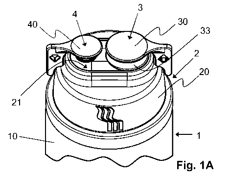
The figures show an illustrative embodiment of a sealing cap 2 which can be
attached to
a container 1, in particular in the form of a bottle, for instance a plastics
bottle or a glass
bottle, in order to seal the container 1 to the outside and provide access
channels for the
filling or removal of a medical liquid.
The sealing cap 2 is attached to a container body 10 of the container 1 and
sealingly
connected, for instance welded or bonded, to the container body 10.
The sealing cap 2 has a cap body 20, which on a top side 21 has two connection
devices
3, 4 for the connection of different conveying devices. The connection devices
3, 4
respectively have a sealing element 31, 41, which is accommodated in a holding
device
32, 42 in the form of a positive-locking receptacle on the cap body 20 and is
clampingly
held on the holding device 32, 42. The sealing element 31 and/or the sealing
element 41
is or are held in the cap body, in particular on the holding device 32, 42,
solely by means
of clamping. In particular, the holding devices 32 and 42 are respectively
configured as a,
preferably annular, beaded rim.
In the initial state of the sealing cap 2, with not yet inserted sealing
elements 31, 41, the
holding devices 32, 42 are not yet bent over. The holding devices 32, 42
extend initially
downward and form the walls of a type of empty sleeve (not represented in the
figures).
Into these still empty sleeves 32, 42 are then respectively inserted the two
sealing
elements 31, 41. For the fixing of the sealing elements 31, 41, the sleeve
walls 32, 42 are
subsequently bent over in the direction of the inside of the sleeve. The
sealing elements
31, 41 are thereby fastened in the respective connection device 3, 4 by means
of
clamping. In the first connection device 3, the beaded rim 32 extends
preferably around
the ring collar 314 of the sealing element 31 in an inward and upward
direction. The
beaded rim 32 undergrips and back-grips the ring collar 314 of the sealing
element 31. In
contrast, in the second connection device 4, the beaded rim 42 extends around
the
marginal portion 413 of the sealing element 41 only substantially inward. The
beaded rim
42 undergrips substantially only the marginal portion 413 of the sealing
element 41. The
CA 03038173 2019-03-25
WO 2018/060333 11
PCT/EP2017/074631
beaded rim 32 and the beaded rim 42 are thus formed by bent-over wall portions
and are
also recognizable and distinguishable as such, in particular in relation to an
injection-
molded portion.
The sealing elements 31, 41 serve to outwardly seal openings 321, 421 on the
top side
21 of the cap body 20, wherein, to this end, a respective sealing head 310,
410 of the
sealing element 31, 41 projects into the associated opening 321, 421 and
sealingly
closes this off. With holding devices 32 and 42 initially not bent over, the
sealing
elements 31, 41 are inserted into the openings 321, 421. For the fixing of the
sealing
elements 31 and 42, the holding devices 32 and 42 are then bent over.
The connection devices 3, 4 are in an initial state, represented in fig. 1A,
2A and 2B,
respectively covered via a break-off piece 30, 40 and sealed in the outward
direction in
such a way that the openings 321, 421, with the sealing elements 31, 41
arranged
therein, are not accessible from the outside and are protected against
contamination.
Preferably, the interior formed by the break-off piece 30, 40 is sterile.
The first connection device 3 comprises on its top side a further elevation
33. The
elevation 33 extends out of the top side of the sealing cap 2. The outer rim
of the opening
321 is arranged in the outer side of the elevation 33. The elevation 33 is
here a circular
elevation 33, which extends in particular concentrically around the opening
321. In
particular, the visibility and/or accessibility of the puncture site in the
connection device 3
can thereby be improved. In particular, the stability of the first connection
device 3, for
example upon insertion of a spike, can also be improved. The elevation 33 has,
at the
transition to the top side of the sealing cap 2 toward the outer side, a
larger step than to
the center of the sealing cap 2.
A first connection device 3 serves for the removal of a medical liquid from
the container
1. By contrast, another, second connection device 4 serves for the feeding of
a medical
.. liquid into the container 1. The removal of a medical liquid is realized
via a conveying
device in the form of a removal device formed, for instance, by an infusion
set, which
removal device has a pin of comparatively large cross section and can be
attached with
the pin to the sealing element 31 of the associated connection device 3. The
feeding of a
medical liquid is realized, by contrast, via a conveying device in the form of
a syringe,
which can be attached with an injection cannula to the sealing element 41 of
the
associated, second connection device 4 in order to pierce the sealing element
41.
CA 03038173 2019-03-25
WO 2018/060333 12
PCT/EP2017/074631
Because the pin of the removal device has a comparatively large cross section,
the
associated opening 321 of the connection device 3 is also comparatively large,
and
correspondingly, the, in its basic shape, rotationally symmetric sealing
element 31 has a
sealing head 310 of comparatively larger diameter. Preferably, the sealing
head 310 of
the first sealing element 31 possesses a diameter of preferredly from 5 mm to
8 mm,
and/or the sealing head 410 of the second sealing element 41 a diameter of 4
mm to 6
mm.
By contrast, the opening 421 of the other, second connection device 4 is
smaller, and
correspondingly, the sealing head 410 of the second sealing element 41, which
sealing
head is extended into the opening, has a comparatively smaller diameter.
Detailed, separate illustrations of the sealing elements 31, 41 are
represented in fig. 4A-
4D and fig. 5A-5D.
The first sealing element 31 has a sealing head 310 having an outward
pointing,
substantially flat outer side 311. Adjoining the sealing head 310 ¨ to the
rear of the outer
side 311 ¨ is a sealing body 312, which is connected via a circumferential
flange 313 to a
likewise peripherally circumferential ring collar 314. Via the ring collar
314, the sealing
element 31 lies in an opening 320 of the holding device 32 and is by this
means held
clampingly on the holding device 32. A bottom side 315 of the sealing element
31 points
into an interior 20 of the sealing cap 2 (see, for example, fig. 4B). The
bottom side 315 of
the first sealing element 31 is here substantially flat. In the first sealing
element 31, the
top side of the ring collar 314 is situated lower than the outer side or top
side 311 of the
sealing head 310. Moreover, the bottom side of the ring collar 314 is situated
lower than
the inner side or bottom side 315 of the first sealing body 31. The ring
collar 314 thus
extends beyond the bottom side 315.
The other, second sealing element 41 likewise has a rotationally symmetric
shape and
consists of a sealing head 410, which, to the rear of a substantially
concavely curved
outer side 411, is adjoined by a cylindrical sealing body 412. Via this
cylindrical sealing
body 412, the sealing element 41 is secured directly in an opening 420 of the
associated,
second holding device 42, in that a marginal portion 413 of the sealing
element 41 is held
clampingly in the opening 420 of the holding device 42. A bottom side 414 of
the sealing
element 41 points toward the interior 200 of the sealing cap 2. The bottom
side 414 of
the second sealing element 41 is here substantially flat.
CA 03038173 2019-03-25
WO 2018/060333 13
PCT/EP2017/074631
The maximum thickness ¨ viewed along an attachment direction A in which a
conveying
device is to be attached to a respectively associated sealing element 31, 41 ¨
of the first
sealing element 31, measured between the outer side 311 and the inner side
315, is
smaller than the maximum thickness of the other, second sealing element 41, in
turn
measured between the outer side 411 and the inner side 414. The different
shaping in
terms of diameter and thickness is dictated by the fact that, upon the
attachment of a pin,
the associated, first sealing element 31 has to be pushed aside to a
substantially greater
extent than when an injection cannula is attached to the associated, second
sealing
element 41. Upon the attachment of a pin, the first sealing element 31 can
thus be
favorably pierced and displaced. The same applies to the second sealing
element 41
upon attachment of an injection cannula.
Both sealing elements 31, 41 reseal themselves automatically when the
respectively
associated conveying device is in turn removed from the connection device 3,
4.
Because the sealing element 31 is on its outer side 311 substantially flat and
is
substantially aligned with the top side 21 of the cap body 20, the sealing
element 31 can
be favorably dabbed or wiped for disinfection purposes, as can possibly be
prescribed by
legal requirements. Preferably, the outer side of the sealing element 31 lies
substantially
in the same plane as the upper rim of the opening 321. Preferably, the rim of
the outer
side of the sealing element 41 also lies substantially in the same plane as
the rim of the
opening 421. It can also be situated somewhat lower. Due to the concave outer
side 411,
the center of the sealing element 41 is situated lower than the upper rim of
the opening
421. Preferably, the central region of the sealing head 410 possesses a, by
0.1 to 1 mm,
lower thickness than the marginal region of the sealing head 410. In
particular, due to the
shaping of the sealing elements 31, 41 on their outer sides 311, 411 and the
positioning
in the openings 321, 421, it is possible to ensure that the outer sides 311,
411 can be
reached by a suitable disinfecting tool, for instance a swab or a wiping
cloth.
For the attachment of a conveying device to an associated connection device 3,
4, the
following procedure is basically adopted.
In an initial state, the sealing cap 2 connected to the container 1 is present
with break-off
pieces 30, 40 fixedly arranged thereon. The break-off pieces 30, 40 are
configured
integrally with the cap body 20 and are connected to the cap body 20 via
circumferential
predetermined breaking points 300, 400 in such a way that the outer sides 311,
411 of
the sealing elements 31, 41 are outwardly covered.
CA 03038173 2019-03-25
WO 2018/060333 14
PCT/EP2017/074631
If a conveying device is intended to be attached to an associated connection
device 3, 4,
then the respective break-off piece 30, 40 is removed from the cap body 20 by
a user
gripping the break-off piece 30, 40 between his fingers and breaking it off
from the cap
body 20 along the predetermined breaking point 300, 400. In this way, the
respective
sealing element 31, 41 is exposed, so that the conveying device can be
attached to the
outer side 311, 411 of the sealing element 31, 41 (not represented in the
figures).
By means of a suitable puncturing tool, the sealing element 31, 41 is now
pierced, so that
a flow connection between a body of the respective conveying device and the
inside of
the container 1 is created, so that a medical liquid can be filled into the
container 1 or
removed from the container 1.
In order to facilitate the insertion of a spike into the sealing element 31,
the sealing
element 31, starting from its outer side 311, is partially slotted. The slot
316 is here
configured as a cross slot (see, in this regard, in particular figures 4A to
4D). This cross
slot 316 serves at the same time also as a marking in order to highlight the
puncture
region to the user. In order to still further improve the visibility of the
puncture site, on the
outer side 311 of the sealing element 31 are further arranged elevations or
webs 317.
The insertion region for the spike on the outer side 311 of the sealing
element 31, which
insertion region is defined by the intersecting slots 316, is additionally
enclosed by an
annularly circumferential web 317. The annularly circumferential web 317 is
respectively
broken at several places. The slots 316 extend through the gaps. As a result,
a type of
target is provided for the user. The webs 317 can lie level with the opening
rim of the
opening 321, or else project somewhat beyond the top side 21 of the cap 2.
That is
dependent on the contact pressure with which the sealing element 31 is fixed
in the
opening 321.
On the top side and bottom side of the ring collar 314 (of the sealing element
31), a
plurality of spacers 318 are arranged distributed over the periphery. The
spacers 318 are
configured as elevations or webs. These here extend, by way of example,
radially
outward. Similarly, a plurality of spacers 418 are arranged distributed on the
inner side or
bottom side 414 of the sealing element 41. The spacers 418 are here configured
as small
bosses. These spacers 318, 418 prevent or reduce adhesion of the sealing
elements 31,
41 during storage. An automated gripping and insertion of the sealing elements
31, 41
into the cap body 20 can thereby be facilitated.
CA 03038173 2019-03-25
WO 2018/060333 15
PCT/EP2017/074631
The sealing cap 2 can, with its cap body 20, preferably be made of plastic,
for instance
by means of plastic injection molding. The break-off pieces 30, 40 of the
connection
devices 3, 4 are herein initially formed in one piece with the cap body and
can be broken
off from the cap body 20 in order to gain access to one of the sealing
elements 31, 41.
While the cap body 20 is made of a comparatively rigid plastics material, the
sealing
elements 31, 41 are made of a comparatively soft, elastic material, for
instance
polyisoprene or a thermoplastic elastomer.
The idea underlying the invention is not limited to the previously depicted
illustrative
embodiments, but is in principle also able to be implemented in embodiments of
wholly
different type.
Since the outward pointing outer side of the sealing elements is easily
accessible, the
sealing elements can on their outer sides be wiped or dabbed in a simple,
effective
manner for disinfection purposes.
In principle, a sealing cap can also have just one connection device, having a
sealing
element, or more than two connection devices, each having a sealing element.
Reference symbol list
1 container
10 container body
2 sealing cap
20 cap body
200 interior
21 top side
3 connection device
break-off piece
300 predetermined breaking point
31 sealing element
310 sealing head
311 outer side
312 sealing body
CA 03038173 2019-03-25
WO 2018/060333 16
PCT/EP2017/074631
313 flange
314 ring collar
315 inner side
316 slot or cross slot
317 marking or burr
318 spacer or web
32 holding device or beaded rim
33 elevation
320 opening
321 opening
4 connection device
40 break-off piece
400 predetermined breaking point
41 sealing element
410 sealing head
411 outer side
412 sealing body
413 marginal portion
414 inner side
418 spacer or boss
42 holding device or beaded rim
420 opening
421 opening
A attachment direction