Note : Les descriptions sont présentées dans la langue officielle dans laquelle elles ont été soumises.
CA 03038920 2019-03-29
WO 2018/091496
PCT/EP2017/079263
1
AIR, ACOUSTIC AND/OR FIRE SEALING DEVICE
BACKGROUND OF THE INVENTION
[0001] Air, acoustic, and/or fire sealing devices, typically located in
openings in walls,
floors, and/or ceilings, and having pipes, fibers, and/or cables passing
therethrough, generally
prevent the spread of smoke and/or other airborne media throughout an area
such as facility,
thereby limiting damage to the area, and providing occupants more time to
safely evacuate
the area. Alternatively, or additionally, the devices also prevent the passage
of sound, as the
sound could compromise privacy and/or frighten the occupants and therefore
adversely
impact the evacuation. If desired, the devices can be designed as fire stop
devices, containing
intumescent material that expands when exposed to extreme heat of the fire,
sealing the
openings to prevent the spread of flame and combustion through the openings.
[0002] However, there is a need for improvement of existing air, acoustic
and/or fire
sealing devices. The present invention provides for ameliorating at least some
of the
disadvantages of the prior art. These and other advantages of the present
invention will be
apparent from the description as set forth below.
BRIEF SUMMARY OF THE INVENTION
[0003] An embodiment of the invention provides an air, acoustic and/or fire
sealing
device comprising (a) an air, acoustic and/or fire sealing insert body
comprising molded foam
material, the body having a first end and a second end and a bulk continuous
with the first
end and the second end; wherein the body has an outer diameter, and the body
is adapted to
allow one or more pipes, fibers and/or cables to pass through the first and
second ends and
the bulk; and, (b) a flexible hollow sleeve comprising a flexible plastic, the
flexible hollow
sleeve having an inner diameter, a first open end and a second open end, the
ends being
axially arranged; wherein the outer diameter of the air, acoustic and/or fire
sealing insert
body is greater than, equal to, or less than, the inner diameter of the
flexible hollow sleeve;
and, the air, acoustic and/or fire sealing insert body is arranged in the
sleeve.
[0004] In a preferred embodiment of the device, the flexible hollow sleeve
comprises a
bellows portion between the first open end and the second open end, the
bellows portion
allowing the sleeve to compress and/or expand in length, and, if necessary,
adjust for
off-centered penetrations.
CA 03038920 2019-03-29
WO 2018/091496
PCT/EP2017/079263
2
[0005] In an embodiment of the device, the flexible hollow sleeve has an
external surface
wherein the external surface at the first open end and at the second open end
comprises
threads.
[0006] In some embodiments, the device further comprises a first flange and
a second
flange, wherein the first flange is slidably engaged with the threads on the
external surface at
the first open end of the sleeve, and the second flange is slidably engaged
with the threads on
the external surface at the second open end of the sleeve and/or the device
further comprises a
first gasket and a second gasket, wherein the first gasket is slidably engaged
with the threads
on the external surface at the first open end of the sleeve, and the second
gasket is slidably
engaged with the threads on the external surface at the second open end of the
sleeve.
BRIEF DESCRIPTION OF THE SEVERAL VIEWS OF THE DRAWING(S)
[0007] Figure lA is a cross-sectional view, Figure IB is a side view,
Figure IC is a
perspective view, and Figure ID is an end view, of an embodiment of an air,
acoustic and/or
fire sealing device comprising (a) first and second air, acoustic and/or fire
sealing insert
bodies, each insert body comprising molded foam material, the body having a
first end and a
second end and a bulk continuous with the first end and the second end;
wherein the body has
an outer diameter, and the body is adapted to allow one or more pipes, fibers
and/or cables to
pass through the first and second ends and the bulk; and, (b) a flexible
hollow sleeve having
an inner diameter, a first open end and a second open end, the ends being
axially arranged;
wherein the outer diameter of each of the first and second air, acoustic
and/or fire sealing
insert bodies are greater than, equal to, or less than, the inner diameter of
the flexible hollow
sleeve; and, the first and second air, acoustic and/or fire sealing insert
bodies are respectively
arranged in the first and second open ends of the sleeve.
[0008] In the embodiment shown in Figure 1A, the first and second insert
bodies each
have molded predetermined patterns at one end, wherein predetermined patterns
of each of
the air, acoustic and/or fire sealing inserts faces outwardly from the open
ends of the sleeve.
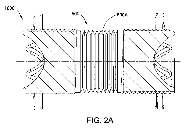
[0009] Figure 2A shows an external view of a portion of a flexible hollow
sleeve
comprising a bellows portion, the bellows portion allowing the sleeve to
compress in length,
Figure 2B shows an external view of a portion of a flexible hollow sleeve
comprising the
bellows portion, the bellows portion allowing the sleeve to expand in length,
and Figure 2C
shows an external view of a portion of the flexible hollow sleeve comprising
the bellows
CA 03038920 2019-03-29
WO 2018/091496
PCT/EP2017/079263
3
portion, wherein the flexible sleeve allows the device to flex, so the device
can be inserted in
angled holes (accommodating off-center drilled holes).
[0010] Figure 3 is a top view of an air, acoustic and/or fire sealing
sleeve insert body for
use in an embodiment of the device according to the present invention, the
insert body
comprising a predetermined pattern of a plurality of slits.
[0011] Figure 4A is a top view, Figure 4B is a bottom view, and Figure 4C
is a
cross-sectional view, of an air, acoustic and/or fire sealing sleeve insert
body for use in an
embodiment of the device according to the present invention, the body
comprising a
predetermined pattern of a plurality of ribs, elevations, and slits, according
to another
embodiment of the present invention. Figure 4D is a cross-sectional view of
another air,
acoustic and/or fire sealing sleeve insert body comprising a predetermined
pattern of a
plurality of ribs, elevations, and slits, for use in a device according to
another embodiment of
the present invention.
[0012] Figure 5A shows an end view of an air, acoustic and/or fire sealing
device
including an insert body shown in Figure 3, and Figure 5B shows pipes, cables
and/or fibers
passing through the air, acoustic and/or fire sealing insert.
[0013] Figure 6A shows an end view of an air, acoustic and/or fire sealing
device
including an insert body shown in Figures IA, 1D, and 4C, 4D, and Figure 6B
show pipes,
cables and/or fibers passing through the air, acoustic and/or fire sealing
insert.
DETAILED DESCRIPTION OF THE INVENTION
[0014] In accordance with an embodiment of the present invention, an air,
acoustic and/or
fire sealing device comprises (a) an air, acoustic and/or fire sealing insert
body comprising
molded foam material, the body having a first end and a second end and a bulk
continuous
with the first end and the second end; wherein the body has an outer diameter,
and the body is
adapted to allow one or more pipes, fibers and/or cables to pass through the
first and second
ends and the bulk; and, (b) a flexible hollow sleeve comprising a flexible
plastic, the flexible
hollow sleeve having an inner diameter, a first open end and a second open
end, the ends
being axially arranged; wherein the outer diameter of the air, acoustic and/or
fire sealing
insert body is greater than, equal to, or less than, the inner diameter of the
flexible hollow
sleeve; and, the air, acoustic and/or fire sealing insert body is arranged in
the sleeve.
Preferably, the device includes first and second air, acoustic and/or fire
sealing insert bodies
arranged in the sleeve.
CA 03038920 2019-03-29
WO 2018/091496
PCT/EP2017/079263
4
[0015] In a preferred embodiment of the device, the flexible hollow sleeve
comprises a
bellows portion between the first open end and the second open end, the
bellows portion
allowing the sleeve to compress and expand in length.
[0016] In an embodiment of the device, the flexible hollow sleeve has an
external
surface, and the external surface at the first open end and at the second open
end comprises
threads.
[0017] In some embodiments, the device further comprises a first flange and
a second
flange, wherein the first flange is slidably engaged with the threads on the
external surface at
the first open end of the sleeve, and the second flange is slidably engaged
with the threads on
the external surface at the second open end of the sleeve and/or the device
further comprises a
first gasket and a second gasket, wherein the first gasket is slidably engaged
with the threads
on the external surface at the first open end of the sleeve, and the second
gasket is slidably
engaged with the threads on the external surface at the second open end of the
sleeve.
[0018] In an embodiment, the device further comprises (1) a first flange
and a second
flange, wherein the first flange is slidably engaged with the threads on the
external surface at
the first open end of the sleeve, and the second flange is slidably engaged
with the threads on
the external surface at the second open end of the sleeve, and/or (2) a first
gasket and a
second gasket, wherein the first gasket is slidably engaged with the threads
on the external
surface at the first open end of the sleeve, and the second gasket is slidably
engaged with the
threads on the external surface at the second open end of the sleeve.
Preferably, the first
flange is disposed closer to the first open end of the sleeve than the first
gasket, and the
second flange is disposed closer to the second open end of the sleeve than the
second gasket.
[0019] In some embodiments of the device, an insert body comprises a
generally
cylindrical body, wherein the bulk has a generally cylindrical shape, and the
flexible hollow
sleeve comprises a generally cylindrical shape.
[0020] In an embodiment of the device, at least the first end of an insert
body comprises a
molded predetermined pattern. For example, the molded predetermined pattern
can comprise
a plurality of ribs and elevations. Alternatively, or additionally, in an
embodiment, the
molded predetermined pattern comprises a plurality of slits passing through
the body in a
direction longitudinal to the body.
[0021] In one preferred embodiment of the device, the molded foam material
of the insert
body comprises polyurethane. In some embodiments, the molded foam material
comprises
an intumescent material.
CA 03038920 2019-03-29
WO 2018/091496
PCT/EP2017/079263
[0022] The air, acoustic and/or fire sealing insert body can have any
desired shape, in one
embodiment, comprising a generally cylindrical body, wherein the bulk has a
generally
cylindrical shape.
[0023] Similarly, the flexible hollow sleeve can have any desired shape
(preferably
generally corresponding to the shape of the sealing insert body), in one
embodiment,
comprising a generally cylindrical shape.
[0024] In a preferred embodiment, the flexible hollow sleeve comprises a
bellows portion
along at least a portion (e.g., at least the central portion) of the length of
the sleeve.
Advantageously, the bellows portion allows the sleeve to be reduced and/or
expanded, in
length, and this adjustment allows the device to be used with walls of
different thicknesses.
[0025] Typically, the (or first) air, acoustic and/or fire sealing insert
body is arranged in
the first open end of the flexible sleeve. In one embodiment of the air,
acoustic and/or fire
sealing device, the first insert body has a molded predetermined pattern, and
the pattern faces
outwardly from the first open end of the sleeve. In another embodiment, the
molded
predetermined pattern of the first air, acoustic and/or fire sealing insert
faces inwardly from
the first open end of the sleeve.
[0026] In a preferred embodiment of the air, acoustic and/or fire sealing
device, it further
comprises an additional (second) air, acoustic and/or fire sealing insert
body, arranged in the
sleeve, typically, wherein the second air, acoustic and/or fire sealing insert
body is arranged
in the second open end of the sleeve. In one embodiment, the second insert
body has a
molded predetermined pattern, and the pattern faces outwardly from the second
open end of
the sleeve, an another embodiment, the molded predetermined pattern of the
second air,
acoustic and/or fire sealing insert faces inwardly from the second open end of
the sleeve.
[0027] Advantageously, one or more of any of the following are provided:
(a) the device
can be easily adjusted for use with walls of different thicknesses; (b) by
avoiding the use of a
metal sleeve, sound transmission can be reduced; (e) the use of a central
bellows portion
decouples the ends of the device with respect to sound transmission, further
reducing sound
transmission; (d) the use of a flexible sleeve allows the device to flex, so
the device can be
inserted in angled holes (accommodating off-center drilled holes); (e) the
foam material
allows for any diameter pipe, cable and/or fiber and/or multiple pipe, cable
and/or fiber
bundle to be inserted and sealed as the foam expands or contracts around the
cable(s),
fiber(s), and/or pipe(s); (f) it is easy to penetrate the insert from either
end; (g) high cable
load is possible; (h) efficient air, acoustic and/or fire and
tightness/blocking, as no visible
CA 03038920 2019-03-29
WO 2018/091496
PCT/EP2017/079263
6
openings around pipe(s), cable(s) and/or fiber(s); (i) long pipe(s), cable(s)
and/or fiber(s) can
be passed through without impacting the foam surface; (j) one step
application, no opening is
necessary, as the pipe(s), cable(s) and/or fiber(s) can easily slide through
the foam (though, if
desired, the inserts can have one or more slits); and (k) cost-effective
production and
assembly. If desired, e.g., wherein the insert comprises an intumescent
material, the inserts
and devices can be used in firestop applications. Alternatively, or
additionally, inserts and/or
devices can be retrofit into existing devices and applications.
[0028] Each of the components of the invention will now be described in
more detail
below, wherein like components have like reference numbers.
[00291 Figures 1A-1D show embodiments of air, acoustic and/or fire sealing
devices
1000, each comprising a hollow flexible sleeve 500 with a first open end 501,
and a second
open end 502 (the sleeve having an inner diameter 515), with a bellows portion
500A
between the first and second open ends, wherein the devices include first and
second air,
acoustic and/or fire sealing insert bodies (100A, 100B), arranged in the open
ends of the
sleeve. In the illustrated embodiments, the insert bodies each have an
optional molded
predetermined pattern, and the pattern faces outwardly from the open ends of
the sleeve.
However, in another embodiment, the device has a single insert body, arranged
in a location
other than an open end. Alternatively, or additionally, if the insert has a
molded
predetermined pattern, the molded predetermined pattern of the insert(s) can
face inwardly
from the open end(s) of the sleeve.
[0030] The flexible hollow sleeve 500 can comprise any suitable plastic
material, for
example, blow molded plastic. For some fire sealing applications, an
embodiment of the
device can include metal threaded sections on each end, and a rubber/plastic
bellows section
that couples the sections together. The sleeve is preferably an integral
sleeve, e.g., as
illustrated. Alternatively, however, the sleeve can comprise a multi-piece
and/or slit sleeve,
e.g., wherein the walls of the sleeve are joined together before installation.
[00311 A portion of the sleeve between the first and second ends comprises
a flexible
bellows portion 500A, which can allow the sleeve to compress and/or expand in
length
(allowing the device to be used with walls of different thicknesses), and, if
desired, allow the
device to flex. The use of a central bellows portion can decouple the ends of
the device with
respect to sound transmission, further reducing sound transmission. In some
embodiments,
the bellows comprises plastic and/or rubber.
CA 03038920 2019-03-29
WO 2018/091496
PCT/EP2017/079263
7
[0032] The illustrated embodiments of the devices also include flanges 510
(also shown
in Figures 5A, 5B, 6A, and 6B) engageable with the sleeve, e.g., for ease of
installing or
embedding the device into a constructional component (e.g., a concrete wall).
If desired, and
as shown, the flange(s) can include openings (and brackets with openings) for
passing
fastening elements such as nails, screws and/or bolts therethrough. If
desired, and as shown
in Figures 1A-1C, the sleeve 500 can include threads 511 so that the flanges
can be slidably
engaged with the sleeves (e.g., for ease in adjustment so that the device can
be used with
constructional components of different thicknesses).
[0033] However, flanges are not required, for example, the device can be
sealed and/or
secured to a structural component via one or more of any of the following
sealants, insulation
(including foam insulation), putty, and or tape (such as sealing tape). If
desired, a flange can
be used in combination with one or more of these sealing and/or securing
components.
[0034] In some embodiments, the device also includes gaskets 520,
engageable with the
sleeve. The use of an air, acoustic and/or fire-tight gasket can be desirable
in providing extra
sealing by sealing the wall penetration behind the flange. Similar to the
arrangement for the
flanges, if desired, and as shown in Figures 1A-1C, the sleeve 500 can include
threads 511 so
that the gaskets and/or flanges can be engaged (slidably and/or threadably
engaged) with the
sleeves (e.g., for ease in adjustment so that the device can be used with
constructional
components of different thicknesses).
[0035] In some embodiments, the device includes an edge bushing. The use of
an edge
bushing can be desirable in providing extra protection to the pipe(s),
cable(s) and/or fiber(s)
when pulled through the insert body/device.
[0036] Figures 3 and 4A-4D show illustrative air, acoustic and/or fire
sealing sleeve
inserts 100 suitable for use in embodiments of the device, the inserts
comprising a body 10
comprising molded foam material, the body having a first end 11 and a second
end 12 and a
bulk 13 continuous with the first end and the second end; wherein at least the
first end
comprises a molded predetermined pattern 50. As shown in Figures 4C and 4D,
the inserts
have an outer diameter 15. The inserts comprise air-sealing (e.g., smoke-
sealing) material,
preferably also providing for sound-sealing, and in some embodiments, fire-
sealing. As used
herein "sealing" air, sound, and/or fire includes "blocking," air, sound,
and/or fire, and "air"
includes airflow, and airborne particles (including, for example, smoke,
airborne pathogens,
and odors).
CA 03038920 2019-03-29
WO 2018/091496
PCT/EP2017/079263
8
[0037] In the embodiment shown in Figure 3, the predetermined pattern 50
includes a
plurality of slits 51. While not shown in the top view of Figure 3, the slits
pass through the
body in a direction longitudinal to the body.
[0038] In the embodiment shown in Figures 4A-4D, the predetermined pattern
50
includes a plurality of ribs 52 and elevations 53 (and valleys 54), as well as
a plurality of slits
51 (wherein the slits pass through the body in a direction longitudinal to the
body).
[0039] The number of ribs and elevations, and the depth of the elevations,
can be selected
to ensure sufficient closure of the foam material around the pipe(s), cable(s)
and/or fiber(s),
e.g., to reduce or avoid gaps. Additionally, or alternatively, the length of
the insert can be
selected to provide, for example, desired air tightness and/or desired
acoustic properties.
[0040] While the embodiments illustrated in Figures 3 and 4A-4D show the
insert 100
comprising a generally cylindrical body, wherein the bulk has a generally
cylindrical shape,
other shapes are possible, e.g., wherein neither the sleeve, nor the insert,
has a cylindrical
form.
[0041] As shown in Figures 5A and 5B, as well as 6A and 6B, the foam
material allows
for any diameter multiple pipe, cable and/or fiber bundle 600 (and/or
individual pipe, cable
and/or fiber) or to be inserted and sealed as the foam expands or contracts
around the pipe(s),
cable(s) and/or fiber(s).
[0042] As noted above, the embodiments illustrated in Figures 3 and 4A-4D
show inserts
comprising generally cylindrical bodies wherein the bulks each have a
generally cylindrical
shape, and Figure lA shows a flexible sleeve having a generally cylindrical
shape.
[0043] A variety of foam materials are suitable. The foam material can be
an open-cell
foam material with very low air permeability, an almost closed-cell foam
material with
extreme low air permeability, and a closed-cell foam material; the foam
material may also be
impregnated to enhance the sealing properties; to provide sufficient tightness
against air,
acoustic and/or fire at least the outer surface of the foam insert should have
closed pores.
[0044] Suitable materials include, for example, cellular rubber (e.g.,
closed-cell cellular
rubber), foam materials such as polyethylene and polyurethane foam or natural
or synthetic
rubber, such as styrene butadiene rubber (SBR), ethylene propylene diene
monomer rubber
(EPDM), or polychloroprene rubber.
[0045] Other materials and processes suitable for producing the air,
acoustic and/or fire
sealing insert are disclosed in, for example, U.S. Patent Application
Publication Number U.S.
2013/0161030. For example, the production of the molded foam body can be by
mold
CA 03038920 2019-03-29
WO 2018/091496
PCT/EP2017/079263
9
foaming, such as reaction injection molding (RIM), according to DE 3917518,
e.g., using
FOMOM) fire prevention foam or the material HILTI CP 65GN forming the
insulation layer.
Material which may be used for the purposes according to the invention are
known from EP
0061024 Al, EP 0051106 Al, EP 0043952 Al, EP 0158165 Al, EP 0116846 Al, and US
3,396,129 A, as well as EP 1347549 Al. Preferably, the molded body comprises a
polyurethane foam capable of intumescence, such as known from EP 0061024 Al,
DE
3025309 Al, DE 3041731 Al, DE 3302416 A, and DE 3411 327 Al.
[0046] In an embodiment, the insert body is produced to have a slightly
greater outer
diameter than the inner diameter of the sleeve at the sleeve location where
the insert body is
arranged, such that the insert remains in place while the
pipe(s)/fiber(s)/cable(s) are being
passed therethrough. However, in other embodiments, the insert can have an
outer diameter
equal to, or less than, the inner diameter of the sleeve. For example, the
sleeve can provide
for air and/or acoustic sealing and have an outer diameter equal to, or less
than, the inner
diameter of the sleeve, and a separate intumescent material can be included
(e.g., as a strip),
such that the foam material is compressed with the sleeve and insert are
inserted into the
sleeve. If desired, the insert body or bodies can be secured (or futher
secured) in the sleeve
via an adhesive, e.g., hot melt glue or other high bond adhesive.
[0047] The insert body can be produced as is known in the art, e.g.,
reaction injection
molded into a form or template, and molded.
[0048] The molded body can comprise a foaming binder, which at least
comprises an ash-
forming and perhaps intumescent material mixture. Here, this binder serves as
a compound-
forming carrier for the ash-forming and perhaps intumescent material mixture.
Preferably the
material mixture is distributed homogeneously in the binder. The compound-
forming carrier
is preferably selected from a group comprising polyurethane, phenol-resins,
polystyrene,
polyolefin, such as polyethylene and/or polybutylene, melamine resin, melamine
resin-foam,
synthetic or natural rubber, cellulose, elastomers, and mixtures therefrom,
with polyurethane
being preferred.
[0049] The ash-forming and in some embodiments intumescent material mixture
may
comprise the fire prevention additives commonly used and known to one trained
in the art,
which in case of fire, thus under the impact of heat, foam and thus form a
froth hindering the
fire from spreading, such as an intumescent material based on an acid former,
a compound
yielding carbon, and a gas former. Preferably the intumescent material
comprises a salt or an
ester of an inorganic, non-volatile acid as the acid former, selected from
sulfuric acid,
CA 03038920 2019-03-29
WO 2018/091496
PCT/EP2017/079263
phosphoric acid, and boric acid, a polyhydroxy-compound as the compound
yielding carbon,
and/or a thermoplastic or duroplastic polymer resin binder, and as a gas
former a
chloroparaffin, melamine, a melamine compound, particularly melamine
cyanurate,
melamine phosphate, melamine polyphosphate, tri(hydroxyl ethyl)-cyanurate,
cyanamide,
dicyanamide, dicyanadiamide, biguanidine, and/or a guanidine salt,
particularly guanidine
phosphate or guanidine sulfate.
[0050] The compound-forming carrier may further comprise an inorganic
compound as
an ablative additive, which comprises water, e.g., water of crystallization,
tightly bonded and
not evaporating at temperatures up to 100 C, however releases it in case of
fire at 120 C and
thus is able to cool temperature-guiding parts, preferably an inorganic
hydroxide or hydrate,
particularly aluminum hydroxide, aluminum oxide hydrate, or partially hydrated
aluminum
hydroxides releasing water preferably at fire temperature and/or when
subjected to flames.
However, other inorganic hydroxides or hydrates releasing water when subjected
to flames
may also be used, such as described in EP 0 274 068 A2.
[0051] Such compounds, which may be used as mixtures of material in the
fire
prevention insert according to one or more embodiments of the invention, are
known to one
trained in the art and disclosed, for example, in the following publications,
which are hereby
included by of reference: DE 30 25 309 Al, DE 30 41 731 Al, DE 33 02 416 Al,
DE 34 11
327 Al, EP 0 043 952 B1, EP 0 051 106 Bl, EP 0 061 024 BI, EP 0 116 846 Bl, EP
0 158
165 B1, EP 0 274 068 A2, EP I 347 549 Al, EP 1 641 895 B I, and DE 196 53
503A1.
[0052] All references, including publications, patent applications, and
patents, cited
herein are hereby incorporated by reference to the same extent as if each
reference were
individually and specifically indicated to be incorporated by reference and
were set forth in
its entirety herein.
[0053] The use of the terms "a" and "an" and "the" and "at least one" and
similar
referents in the context of describing the invention (especially in the
context of the following
claims) are to be construed to cover both the singular and the plural, unless
otherwise
indicated herein or clearly contradicted by context. The use of the term "at
least one"
followed by a list of one or more items (for example, "at least one of A and
B") is to be
construed to mean one item selected from the listed items (A or B) or any
combination of two
or more of the listed items (A and B), unless otherwise indicated herein or
clearly
contradicted by context. The terms "comprising," "having," "including," and
"containing"
are to be construed as open-ended terms (i.e., meaning "including, but not
limited to,") unless
CA 03038920 2019-03-29
WO 2018/091496
PCT/EP2017/079263
11
otherwise noted. Recitation of ranges of values herein are merely intended to
serve as a
shorthand method of referring individually to each separate value falling
within the range,
unless otherwise indicated herein, and each separate value is incorporated
into the
specification as if it were individually recited herein. All methods described
herein can be
performed in any suitable order unless otherwise indicated herein or otherwise
clearly
contradicted by context. The use of any and all examples, or exemplary
language (e.g., "such
as") provided herein, is intended merely to better illuminate the invention
and does not pose a
limitation on the scope of the invention unless otherwise claimed. No language
in the
specification should be construed as indicating any non-claimed element as
essential to the
practice of the invention.
[0054] Preferred embodiments of this invention are described herein,
including the best
mode known to the inventors for carrying out the invention. Variations of
those preferred
embodiments may become apparent to those of ordinary skill in the art upon
reading the
foregoing description. The inventors expect skilled artisans to employ such
variations as
appropriate, and the inventors intend for the invention to be practiced
otherwise than as
specifically described herein. Accordingly, this invention includes all
modifications and
equivalents of the subject matter recited in the claims appended hereto as
permitted by
applicable law. Moreover, any combination of the above-described elements in
all possible
variations thereof is encompassed by the invention unless otherwise indicated
herein or
otherwise clearly contradicted by context.