Sélection de la langue

Search

Sommaire du brevet 3040218 

Énoncé de désistement de responsabilité concernant l'information provenant de tiers

Une partie des informations de ce site Web a été fournie par des sources externes. Le gouvernement du Canada n'assume aucune responsabilité concernant la précision, l'actualité ou la fiabilité des informations fournies par les sources externes. Les utilisateurs qui désirent employer cette information devraient consulter directement la source des informations. Le contenu fourni par les sources externes n'est pas assujetti aux exigences sur les langues officielles, la protection des renseignements personnels et l'accessibilité.

Disponibilité de l'Abrégé et des Revendications

L'apparition de différences dans le texte et l'image des Revendications et de l'Abrégé dépend du moment auquel le document est publié. Les textes des Revendications et de l'Abrégé sont affichés :

  • lorsque la demande peut être examinée par le public;
  • lorsque le brevet est émis (délivrance).
(12) Brevet: (11) CA 3040218
(54) Titre français: APPAREIL ET PROCEDE DESTINES A UN SYSTEME DE VIDEO EN TEMPS REEL BI-OPTIQUE
(54) Titre anglais: APPARATUS AND METHOD FOR A BIOPTIC REAL TIME VIDEO SYSTEM
Statut: Octroyé
Données bibliographiques
(51) Classification internationale des brevets (CIB):
  • G02B 27/01 (2006.01)
  • H04N 7/18 (2006.01)
  • A63F 13/25 (2014.01)
  • H04N 5/247 (2006.01)
(72) Inventeurs :
  • HILKES, ROBERT G. (Canada)
(73) Titulaires :
  • GENTEX CORPORATION (Etats-Unis d'Amérique)
(71) Demandeurs :
  • ESIGHT CORP. (Canada)
(74) Agent: PERLEY-ROBERTSON, HILL & MCDOUGALL LLP
(74) Co-agent:
(45) Délivré: 2021-12-21
(22) Date de dépôt: 2012-06-01
(41) Mise à la disponibilité du public: 2013-12-05
Requête d'examen: 2019-04-15
Licence disponible: S.O.
(25) Langue des documents déposés: Anglais

Traité de coopération en matière de brevets (PCT): Non

(30) Données de priorité de la demande: S.O.

Abrégés

Abrégé français

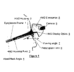
Une méthode et un appareil servant à afficher une image vidéo de manière non immersive au moyen dun écran daffichage près de lil de sorte que lutilisateur peut choisir de regarder limage affichée ou son environnement naturel en modifiant langle de son cou ou de ses yeux. Linvention porte également sur lintégration de lentilles correctrices dans la chaîne du système de vision de lécran daffichage près de lil. De plus, linvention concerne lutilisation de détecteurs de mouvement et de position intégrés à lappareil porté sur la tête afin de permettre la stabilisation automatique de limage vidéo. Finalement, linvention porte sur lutilisation de détecteurs de mouvement et de position intégrés à lappareil porté sur la tête afin dajuster automatiquement langle vertical de la caméra, de lécran daffichage électronique ou des deux grâce à la détection de la position angulaire de la tête de lutilisateur.


Abrégé anglais

A method and apparatus of displaying an electronic video image using a head- worn near-to-eye display in a non-immersive fashion, such that the wearer can choose, through simple adjustments of their neck and eye angles, to either look at the displayed video image or their natural environment. The invention also relates to the incorporation of prescription lenses into the optical chain of the near-to-eye display. The invention also relates to the use of motion and position sensors incorporated into the head-worn device to enable automatic stabilization of the video image. The invention also relates to the use of motion and position sensors incorporated into the head-worn device to automatically adjust the vertical angle of either the camera or the electronic display or both, by sensing the vertical angular position of the user's head.

Revendications

Note : Les revendications sont présentées dans la langue officielle dans laquelle elles ont été soumises.


CA03040218
CLAIMS
What is claimed is:
1. A head-worn device comprising:
a frame configured to mount onto a wearer's head including a first portion
configured to be
disposed on a first side of the wearer's head and a second portion configured
to be
disposed on a second distal side of the wearer's head; and
a binocular electronic near-to-eye display assembly pivotally attached to the
first portion of the
frame and pivotally attached to the second portion of the frame such that the
electronic
near-to-eye display is restricted to pivot vertically across and in front of
the wearer's
face and pivots about an axis parallel to an axis defined between a left
temple of the
wearer's head and a right temple of the wearer's head; wherein
the wearer views their environment directly with the electronic near-to-eye
display assembly
pivoted upwards in front of a forehead of the wearer's head above and out of
their
horizontal forward line of sight; views first visual content presented on the
electronic
near-to-eye display with the electronic near-to-eye display assembly pivoted
down in
front of their eyes into their line of sight; and
the electronic near-to-eye display automatically pivots into different
positions based upon a
position of the wearer's head.
2. The head-worn device according to claim 1, wherein
when the electronic near-to-eye display is pivoted down in front of the
wearer's eyes the
viewer's direct view of their external environment is either
blocked by the electronic near-to-eye display except peripherally; or
through the electronic near-to-eye display.
3. The head-worn device according to claim 1, wherein
the electronic near-to-eye display incorporates a camera for providing the
first visual content;
and
the vertical angle of the camera is at least one of manually adjustable or
adjusts automatically
according to a position of the wearer's head.
7
Date Recue/Date Received 2021-05-10

CA03040218
4. The head-worn device according to claim 1, further comprising:
a camera associated with the wearer;
an orientation sensor; and
a motion sensor,
wherein image content acquired by the camera is stabilized using motion
information provided
by the orientation and motion sensors for presentation to the wearer as the
first visual
content.
5. The head-worn device according to claim 4, wherein
the vertical angle of the camera is automatically adjusted in dependence upon
at least a task
being performed by the wearer of the head-worn device and using information
provided by at
least one of the orientation sensor and the motion sensor.
6. The head-worn device according to claim 1, wherein
the first visual content presented on the electronic near-to-eye display is
second content
received from an external source overlaid to third content established in
dependence upon the
wearer's field of view.
7. The head-worn device according to claim 1, wherein
the electronic near-to-eye display assembly comprises a display and an optical
element having
a first surface adjacent the display and a second surface configured to be
disposed
towards a user's eye when the electronic near-to-eye display assembly is worn,
wherein
a normal perpendicular to the surface of the display is orthogonal to a line
of sight of the user
of the head-worn device when the user's head is in the second position.
8. The head-worn display according to claim 1, wherein
the wearer views second visual content presented on the electronic near-to-eye
display when
the wearer's head is pivoted forward.
9. The head-worn display according to claim 8, wherein
the first visual content and the second visual content are established by
defining different areas
of pixels within an image obtained from at least one of a camera and an
external image source.
8
Date Recue/Date Received 2021-05-10

CA03040218
10. The head worn device according to claim 1, further comprising
a camera for providing the first visual content forming part of the electronic
near-to-eye
display;
a motor coupled to the camera and to a controller forming part of the
electronic near-to-eye
display; and
at least one of a position sensor providing position data to the controller
relating to a position
of the electronic near-to-eye display and a motion sensor providing motion
data to the
controller relating to motion of the electronic near-to-eye display; wherein
the vertical angle of the camera adjusts automatically in dependence upon the
controller
processing the at least one of position data and motion data according to a
position of
the wearer's head.
11. The head worn device according to claim 1, wherein
the first visual content presented on the electronic near-to-eye display is
stabilized using motion
information provided by at least one of an orientation sensor forming part of
the
electronic near-to-eye display and a motion sensor forming part of the
electronic near-
to-eye display; and
the stabilization is applied for translational and rotational vectors.
12. The head worn device according to claim 4, wherein
the stabilization is applied for translational and rotational vectors.
13. A head mounted electronic near-to-eye display module, the electronic near-
to-eye display
module comprising:
a display electronics circuit in communication with a source of visual
content;
a head mounted display optics having a first surface adjacent the display
electronics circuit and
a second surface disposed towards a wearer's head; and
a first hinge for pivotally attaching the electronic near-to-eye display
module to a first portion
of a frame which is configured to be disposed on a first side of the wearer's
head when
worn by the wearer;
a second hinge for pivotally attaching the electronic near-to-eye display
module to a second
portion of the frame which is configured to be disposed on a second distal
side of the
wearer's head when worn by the wearer; wherein
9
Date Recue/Date Received 2021-05-10

CA03040218
the first hinge and second hinge restrict the electronic near-to-eye display
to pivoting vertically
across and in front of the wearer's face when worn by the wearer;
the electronic near-to-eye display pivots about an axis parallel to an axis
defined between a left
temple of the wearer's head and a right temple of the wearer's head;
the wearer views their environment directly when the electronic near-to-eye
display assembly
is pivoted upwards in front of a forehead of the wearer's head above and out
of their
horizontal forward line of sight and views first visual content presented on
the
electronic near-to-eye display with the electronic near-to-eye display
assembly pivoted
down in front of their eyes into their line of sight; and
the head mounted electronic near-to-eye display automatically pivots into
different positions
based upon a position of the wearer's head.
14. The head mounted electronic near-to-eye display module according to claim
13, wherein
when the electronic near-to-eye display is pivoted down in front of the
wearer's eyes the
viewer's direct view of their external environment is either
blocked by the electronic near-to-eye display except peripherally; or
through the electronic near-to-eye display.
15. The head mounted electronic near-to-eye display module according to claim
13, wherein
the head mounted electronic near-to-eye display incorporates a camera for
providing the first
visual content; and
the vertical angle of the camera is at least one of manually adjustable or
adjusts automatically
according to a position of the wearer's head.
16. The head mounted electronic near-to-eye display module according to claim
13, further
comprising:
a camera associated with the wearer;
an orientation sensor; and
a motion sensor,
wherein image content acquired by the camera is stabilized using motion
information provided
by the orientation and motion sensors for presentation to the wearer as the
first visual
content.
Date Recue/Date Received 2021-05-10

CA03040218
17. The head mounted electronic near-to-eye display module according to claim
16, wherein
the vertical angle of the camera is automatically adjusted in dependence upon
at least a task
being performed by the wearer of the head mounted electronic near-to-eye
display module and
using information provided by at least one of the orientation sensor and the
motion sensor.
18. The head mounted electronic near-to-eye display module according to claim
13, wherein
a normal perpendicular to the surface of the display electronics circuit is
orthogonal to a line
of sight of a user of the head mounted electronic near-to-eye display module.
19. The head mounted electronic near-to-eye display module according to claim
13, wherein
the first visual content presented on the electronic near-to-eye display is
second content
received from an external source overlaid to third content established in
dependence upon the
wearer's field of view.
20. The electronic near-to-eye display module according to claim 13, further
comprising
a camera for providing the first visual content forming part of the electronic
near-to-eye
display;
a motor coupled to the camera and to a controller forming part of the
electronic near-to-eye
display; and
at least one of a position sensor providing position data to the controller
relating to a position
of the electronic near-to-eye display and a motion sensor providing motion
data to the
controller relating to motion of the electronic near-to-eye display; wherein
the vertical angle of the camera adjusts automatically in dependence upon the
controller
processing the at least one of position data and motion data according to a
position of
the wearer's head.
21. The electronic near-to-eye display module according to claim 13, further
comprising
a camera for providing the first visual content forming part of the electronic
near-to-eye
display;
a motor coupled to the camera and to a controller forming part of the
electronic near-to-eye
display; and
at least one of a position sensor providing position data to the controller
relating to a position
of the electronic near-to-eye display and a motion sensor providing motion
data to the
controller relating to motion of the electronic near-to-eye display; wherein
11
Date Recue/Date Received 2021-05-10

CA03040218
the vertical angle of the camera adjusts automatically in dependence upon the
controller
processing the at least one of position data and motion data according to a
position of
the wearer's head.
22. The electronic near-to-eye display module according to claim 16, wherein
the stabilization is applied for translational and rotational vectors.
12
Date Recue/Date Received 2021-05-10

Description

Note : Les descriptions sont présentées dans la langue officielle dans laquelle elles ont été soumises.


AiARATUS Aril) IVIETIIIOD FORAinOFrIC REAL Tir VIDEOSYSTEM
CROSS-REFERENCE TO RELATED APPLICATIONS
[001] This application claims the benefit of priority as a divisional of CA
2,875,261 which
was filed December 1, 2014 entitled "Apparatus and Method for a Bioptic Real
Time Video
System", which itself claims priority as a national phase entry of World
Intellectual Property
Office PCT/CA2012/000532 filed June 1, 2012 entitled "Apparatus and Method for
a Bioptic
Real Time Video System."
FIELD OF THE INVENTION
[002] The invention relates generally to the field of wearable electronic
displays and more
specifically to the field of vision care.
BACKGROUND OF THE INVENTION
[003] There are numerous applications for lightweight head-worn near-to-eye
displays.
These are commonly called Head Mounted Displays (HMD). HMDs display to the eye
an
electronically rendered image such that the wearer perceives that they are
watching a sizeable
electronic display at some distance in front of them. The applications that
use such HMDs are
numerous, including but not limited to virtual reality, electronic gaming,
simulation
environments such as for military simulations or flight simulators, medical
applications such
as for the enhancement of sight, and consumer applications such as the ability
to view videos
in a mobile setting.
[004] One of the fundamental challenges of HMDs is the tradeoff between the
display's
Field of View (FOV), being the size of the virtual display as perceived by the
wearer, and
pixel size. FOV is normally defined as the number of angular degrees subtended
within the
viewer's overall field of vision, horizontally, vertically, or on the
diagonal. Horizontal FOV
dimensions in the range of 20-30 degrees are typical, with larger dimensions
being possible at
significant expense. Pixel size is similarly expressed as the number of
angular arc minutes
(1/60th of a degree) subtended by a single, typically square pixel element. As
one might
- I -
CA 3040218 2019-04-15

expect, to achieve a larger FOV with a given pixel resolution (number of
pixels), results in a
larger pixel size, and consequent loss of image detail.
1005] Peripheral vision is that portion of the human field of vision outside
the center, say,
10-15 degrees FOV. Peripheral vision is extremely important in some HMD
applications,
especially those in which the wearer must maintain a connection with their
natural
environment to contextualize their situation, and enable way finding,
orientation, and
mobility. To provide significant peripheral vision via the electronic display
requires an
extremely large (and expensive) HMD. Alternately HMDs which provide a
significant natural
peripheral vision external to the HMD housing, provide a very limited virtual
electronic
FOV.
[006] Many HMD applications can benefit from the incorporation of a live
camera into the
HMD, such that the wearer can not only view electronic data from a source,
such as a video
file, but also live video images of the world in front of them. Image
processing can be used to
enhance the live camera image before it is presented to the eye, providing
magnification,
enhancement of brightness, or improved contrast for example.
[007] In HMD systems that are to be used for multiple activities, different
camera angles
may be required for different tasks. For example, to observe an object a
distance, the camera
angle should be nearly horizontal relative to the horizon when the wearer's
neck is straight,
and their gaze angled at the horizon. On the other hand, to view hand-held
objects at a close
distance requires a camera that is angled downward, in order to avoid a highly
exaggerated
downward neck posture. In this manner, the angle of the camera mimics the
angular
movement of one's eyes in a non-HMD world.
[008] Finally, the angle of the display relative to the eyes is also dependent
on the specific
tasks of the wearer. In certain situations, the wearer would like to look into
the electronic
display only temporarily, and by looking up at an angle higher than their
habitual gaze. In
other situations, the wearer would prefer a more immersive usage model, where
the electronic
display is directly in front of their normal line of gaze.
[009] What is needed then is a general HMD device that is capable of providing
significant
unobstructed peripheral vision outside of the electronic display FOV, while
simultaneously
providing a high resolution video image. Further, the ability to adjust the
angle of the display
and the camera according to the wearer's specific activity would provide
significant comfort
and increased usability.
- 2 -
CA 3040218 2019-04-15

[0010] Other aspects and features of the present invention will become
apparent to those
ordinarily skilled in the art upon review of the following description of
specific embodiments
of the invention in conjunction with the accompanying figures.
SUMMARY OF THE INVENTION
[0011] The ability to quickly alternate as required by the specific task,
between viewing an
image presented in the electronic display and viewing the world without the
electronic
display, enables many possible usage models for an HMD. Furthermore, in an HMD
with an
integrated camera, the ability to adjust the vertical camera angle for
different tasks, viewing
objects distant and close for example, significantly increases the usability
of such a device.
Finally, an HMD whereby the user is able to select the vertical position of
the electronic
display, in order to tradeoff a comfortable immersive video experience versus
maintaining a
broad natural field of view enables the HMD to be used in a variety of user
applications and
postures.
[0012] The invention, in one aspect, relates to a method of orienting an
electronic near-to-eye
display such that the wearer views it slightly above their habitual line of
sight for a given
task. In this manner the wearer, through slight neck and eye angle adjustments
can, with
minimal effort, alternate between the electronic display and their natural
vision.
[0013] In one embodiment, the electronic display is mounted slightly above the
wearer's
habitual line of sight, so that by angling the neck slightly forward and
directing their gaze
slightly upward, they can look into the display. Alternately by angling the
neck slightly back
and directing their gaze slightly down, they can view below the electronic
display using their
natural vision.
10014] In another embodiment, the apparatus incorporates the wearer's
prescription
ophthalmic lenses, so that whether they gaze up into the electronic HMD or
down using their
natural vision, they are able to do so through their prescription lenses. This
embodiment of
the invention alleviates the need to switch between the HMD device and the
wearer's habitual
spectacles.
[0015] In another embodiment the apparatus incorporates a video camera, which
provides the
video information to the electronic display, the angle of the camera being
adjustable as
required by the specific task.
- 3 -
CA 3040218 2019-04-15

[0016] In any of the above embodiments the source of the video may come from a
device
other than the camera, in any standard electronic video format such as MPEG
for example.
[0017] In another embodiment the apparatus may deploy motion sensing
components in
order to facilitate image stabilization for the electronic video image that is
captured by the
camera.
[0018] In another embodiment the motion sensing components could be used to
determine
the angular orientation of the apparatus, so that the vertical camera angle
can be
automatically adjusted based on head position.
BRIEF DESCRIPTION OF THE DRAWINGS
[0019] The invention is pointed out with particularity in the appended claims.
The
advantages of the invention described above, together with further advantages,
may be better
understood by referring to the following description taken in conjunction with
the
accompanying drawings. In the drawings, like reference characters generally
refer to the
same parts throughout the different views. The drawings are not necessarily to
scale,
emphasis instead generally being placed upon illustrating the principles of
the invention.
[0020] FIGS. 1 through 4 are highly schematic diagrams of an embodiment of the
system of
the invention;
[0021] FIG. 5 is a more detailed view of an embodiment of the system for
automatically
adjusting the angle of the camera.
[0022] FIG. 6 is a more realistic rendering of a particular embodiment of the
system of the
invention.
[0023] FIGS. 7A through 7C depict three successive frames of simulated video,
in order to
show how motion vectors can be used for image stabilization.
[0024] FIGS. 8A and 8B show an alternate method of altering the camera angle
through
defining a window on the image sensor rather than by physically altering the
camera angle.
DETAILED DESCRIPTION
[0025] In brief overview and referring to FIG. 1 and FIG. 6, the system in one
embodiment
includes prescription lenses 6 mounted to an eyeglasses frame 1. The Head
Mounted Display
portion of the system comprises a housing 2, which can move relative to the
eyeglasses frame
- 4 -
CA 3040218 2019-04-15

1, about a pivot point 3. The HMD housing 2 incorporates HMD optics 5, a
camera 9, and
HMD electronics 8 (collectively, the "HMD").
[0026] In the orientation depicted in FIG. 1, the wearer's head/neck posture
is angled slightly
back 4, and he is viewing the world 7 through the prescription lens 6, without
the use of the
HMD optics 5 or camera 9.
[0027] In FIG. 2, the head/neck angle 4 is slightly forward, allowing the user
to view the
HMD optics 5 through the same prescription lens 6 by directing their gaze at a
slight upward
angle 7. In this mode, video information viewed through the HMD optics 5 can
be provided
from the video camera 9, oriented at an outward angle 10 such that objects at
a distance can
be viewed in the video image. As discussed, the video could also come from
other sources.
[0028] In FIG. 3 the head/neck angle 4 is unchanged from FIG. 2, but the
camera has been
angled downward on a pivot point 11 so that the camera angle 10 is now aimed
at a nearby
object close at hand, perhaps in the wearer's hands.
[0029] In FIG. 4 the slightly forward head/neck angle 4 remains unchanged, but
the HMD
angle has been significantly lowered by pivoting the HMD housing 2 relative to
the
eyeglasses frame 1, around a pivot point 3. In this orientation the wearer is
able to adopt a
more comfortable viewing angle 7 for near-in tasks. Furthermore, the camera
angle 10 can be
directed further downward because the camera pivot point 11 moves with the HMD
housing
2.
[0030] In FIG. 5, a method is shown whereby a linear motor 12 can be used to
adjust the
vertical angle 10 of the camera 9. The camera rotated around a pivot point 11
that is affixed
to the HMD housing 2. With the adjustment of the camera angle automated thus,
it is possible
to use motion and position sensors embodied in the HMD electronics 8, to
provide positional
data that can be used to control the linear motor 12.
[0031] Alternately, the angle 10 of the camera 9 can be adjusted manually by
the user.
[0032] FIG. 7 shows how the same motion and position sensors embodied in the
HMD
electronics 8 can be used to enable an image stabilization function. FIGS. 7A,
7B, and 7C
show three consecutive frames of video as captured by the camera 9. Because of
the normal
movement of the wearer's head, successive frames of video have a translational
(up/down,
left/right) and rotational (angular) position relative to the previous frame.
The frame depicted
in FIG. 7B for example has shifted to the right/down and rotated slightly
counter-clockwise
relative to the previous frame 7A. The translational vector Al and rotational
angle 01 can be
- 5 -
CA 3040218 2019-04-15

determined from the motion and position sensors embodied in the HMD
electronics 8. By
applying the opposite of the translational vector and the reverse rotational
angle to the pixels
in the video frame 7B, the differences between the two frames 7A and 7B can be
removed.
FIG. 7C carries the example further, showing a frame of video that is now
shifted left/down
and clockwise relative to the previous frame 7B. A new vector A2 and
rotational angle 02 can
be applied, and so forth so that over time, small frame-to-frame variations
caused by the
wearer's head movement are removed from the displayed video. To distinguish
between
minor head movements, for which image stabilization should be applied, and
gross head
movements, which indicate the wearer's scene of interest has changed, requires
that the image
stabilization function only be applied to small translational and rotational
vectors.
[0033] In FIGS. 8A and 8B, the angle of the camera 9 is adjusted not by
physically rotating
the camera as previously discussed. Rather, an area of pixels, or a window 13,
14 can be
defined on the image sensor so that the wearer perceives that the camera angle
is physically
altered. This technique requires a camera system wherein the usable image
sensor area is
larger than the video that is to be displayed to the wearer. Motion and
position sensors
embodied in the HMD electronics 8 can be used to determine the wearer's
head/neck angle 4
and, based on this information, define a capture window 13, 14 that gives the
wearer the
perception of a high or low camera angle 10.
[0034] While the present invention has been described in terms of certain
exemplary
preferred embodiments, it will be readily understood and appreciated by one of
ordinary skill
in the art that it is not so limited, and that many additions, deletions and
modifications to the
preferred embodiments may be made within the scope of the invention as
hereinafter claimed.
Accordingly, the scope of the invention is limited only by the scope of the
appended claims.
- 6 -
CA 3040218 2019-04-15

Dessin représentatif
Une figure unique qui représente un dessin illustrant l'invention.
États administratifs

Pour une meilleure compréhension de l'état de la demande ou brevet qui figure sur cette page, la rubrique Mise en garde , et les descriptions de Brevet , États administratifs , Taxes périodiques et Historique des paiements devraient être consultées.

États administratifs

Titre Date
Date de délivrance prévu 2021-12-21
(22) Dépôt 2012-06-01
(41) Mise à la disponibilité du public 2013-12-05
Requête d'examen 2019-04-15
(45) Délivré 2021-12-21

Historique d'abandonnement

Il n'y a pas d'historique d'abandonnement

Taxes périodiques

Dernier paiement au montant de 125,00 $ a été reçu le 2024-05-21


 Montants des taxes pour le maintien en état à venir

Description Date Montant
Prochain paiement si taxe applicable aux petites entités 2025-06-02 125,00 $
Prochain paiement si taxe générale 2025-06-02 347,00 $ si reçu en 2024
362,27 $ si reçu en 2025

Avis : Si le paiement en totalité n'a pas été reçu au plus tard à la date indiquée, une taxe supplémentaire peut être imposée, soit une des taxes suivantes :

  • taxe de rétablissement ;
  • taxe pour paiement en souffrance ; ou
  • taxe additionnelle pour le renversement d'une péremption réputée.

Les taxes sur les brevets sont ajustées au 1er janvier de chaque année. Les montants ci-dessus sont les montants actuels s'ils sont reçus au plus tard le 31 décembre de l'année en cours.
Veuillez vous référer à la page web des taxes sur les brevets de l'OPIC pour voir tous les montants actuels des taxes.

Historique des paiements

Type de taxes Anniversaire Échéance Montant payé Date payée
Requête d'examen 400,00 $ 2019-04-15
Le dépôt d'une demande de brevet 200,00 $ 2019-04-15
Taxe de maintien en état - Demande - nouvelle loi 2 2014-06-02 50,00 $ 2019-04-15
Taxe de maintien en état - Demande - nouvelle loi 3 2015-06-01 50,00 $ 2019-04-15
Taxe de maintien en état - Demande - nouvelle loi 4 2016-06-01 50,00 $ 2019-04-15
Taxe de maintien en état - Demande - nouvelle loi 5 2017-06-01 100,00 $ 2019-04-15
Taxe de maintien en état - Demande - nouvelle loi 6 2018-06-01 100,00 $ 2019-04-15
Taxe de maintien en état - Demande - nouvelle loi 7 2019-06-03 100,00 $ 2019-05-31
Taxe de maintien en état - Demande - nouvelle loi 8 2020-06-01 100,00 $ 2020-05-01
Taxe de maintien en état - Demande - nouvelle loi 9 2021-06-01 100,00 $ 2021-05-31
Taxe finale 2022-02-14 153,00 $ 2021-11-05
Taxe de maintien en état - brevet - nouvelle loi 10 2022-06-01 125,00 $ 2022-05-10
Taxe de maintien en état - brevet - nouvelle loi 11 2023-06-01 125,00 $ 2023-05-17
Taxe de maintien en état - brevet - nouvelle loi 12 2024-06-03 125,00 $ 2024-05-21
Titulaires au dossier

Les titulaires actuels et antérieures au dossier sont affichés en ordre alphabétique.

Titulaires actuels au dossier
GENTEX CORPORATION
Titulaires antérieures au dossier
ESIGHT CORP.
Les propriétaires antérieurs qui ne figurent pas dans la liste des « Propriétaires au dossier » apparaîtront dans d'autres documents au dossier.
Documents

Pour visionner les fichiers sélectionnés, entrer le code reCAPTCHA :


Pour visualiser une image, cliquer sur un lien dans la colonne description du document. Pour télécharger l'image (les images), cliquer l'une ou plusieurs cases à cocher dans la première colonne et ensuite cliquer sur le bouton "Télécharger sélection en format PDF (archive Zip)" ou le bouton "Télécharger sélection (en un fichier PDF fusionné)".

Liste des documents de brevet publiés et non publiés sur la BDBC .

Si vous avez des difficultés à accéder au contenu, veuillez communiquer avec le Centre de services à la clientèle au 1-866-997-1936, ou envoyer un courriel au Centre de service à la clientèle de l'OPIC.


Description du
Document 
Date
(yyyy-mm-dd) 
Nombre de pages   Taille de l'image (Ko) 
Demande d'examen 2020-04-28 5 262
Paiement de taxe périodique 2020-05-01 1 33
Modification 2020-08-28 13 471
Revendications 2020-08-28 6 265
Demande d'examen 2021-01-29 3 144
Modification 2021-05-10 12 451
Paiement de taxe périodique 2021-05-31 1 33
Revendications 2021-05-10 6 264
Taxe finale 2021-11-05 2 51
Dessins représentatifs 2021-11-22 1 16
Page couverture 2021-11-22 1 49
Certificat électronique d'octroi 2021-12-21 1 2 527
Abrégé 2019-04-15 1 18
Description 2019-04-15 6 279
Revendications 2019-04-15 6 210
Dessins 2019-04-15 6 361
Complémentaire - Certificat de dépôt 2019-05-02 1 73
Paiement de taxe périodique 2019-05-31 1 33
Dessins représentatifs 2019-06-19 1 15
Page couverture 2019-06-19 2 52