Note : Les descriptions sont présentées dans la langue officielle dans laquelle elles ont été soumises.
CA 03042116 2019-04-29
ALUMINUM TERMINAL AND COPPER-ALUMINUM TRANSITION
CONNECTOR
Technical Field
The present invention relates to an aluminum terminal used in a copper-
aluminum
transition connector for an automotive vehicle and a copper-aluminum
transition connector
using the described aluminum terminal.
Background
The connection terminals of electrical apparatus, especially electrical
apparatus for
automotive vehicles, are usually made of copper. A direct connection of these
connection
terminals and aluminum wires (which includes a conductor core and an
insulation layer
wrapped over the conductor core, and the conductor core is mainly made of
aluminum or
aluminum alloy) will result in a large contact resistance. Under a long-term
operation, an
overloading, or a short circuit of the apparatus, an acute temperature rise
can occur on the
connection joint, and thus causes accidents. To this end, a pre-treated copper-
aluminum
connector or a copper-aluminum transition bus bar is generally used in
practice.
A Chinese Utility Model Patent CN 203312469 U discloses a copper-aluminum
joint,
which mainly plays a role of transitional connector between electrical
apparatus and
aluminum wires. The elements involved in the transitional connector mainly
include
aluminum wire, aluminum ferrule, and copper terminal. Specifically, the
aluminum wire
consists of a conductor core and an insulation layer wrapped over the
conductor core. The
aluminum ferrule is sleeved over the aluminum wires. One end of the aluminum
ferrule is
placed on the conductor core at the end portion of the aluminum wire where the
insulation
layer is removed, and the other end of the aluminum ferrule is placed on the
adjacent
insulation layer. The interior of the aluminum ferrule is of a step shape, and
an inner step
surface is matched with an end surface of the insulation layer.
However, there is no limitation about the size of the aluminum ferrule for the
aluminum-copper joint having such a structure. Since the commonly used
aluminum
ferrule generally has a yield strength of about 30 MPa, a small wall thickness
of the
aluminum ferrule when crimped with the aluminum wire will lead to cracks on
the
aluminum ferrule easily, or obvious cracks may appear after some scratches,
thereby
1
CA 03042116 2019-04-29
degrading the overall mechanical properties of the copper-aluminum joint.
While,
increasing the wall thickness of the aluminum ferrule contributes very little
on improving
the crimping performance, mechanical properties, and electrical properties of
the product
and requires a large amount of aluminum material, which greatly increases the
production
cost.
Meanwhile, since the aluminum wire is connected to the aluminum ferrule by
crimping, if the crimping cannot achieve a good connection, it is easy to
leave a gap
between the aluminum ferrule and the conductor core of the aluminum wire, or
between the
conductor cores of the aluminum wire. As a result, it is difficult to isolate
air and water, and
the conductor core will get oxidized and corroded by air. Thus, the resistance
between the
conductor core and the aluminum ferrule is increased, and the performance of
electrical
conductivity between the aluminum wire and the aluminum ferrule is reduced.
Summary
In order to overcome the defects of the prior art, the first objective of the
present
invention is to provide an aluminum terminal which not only can prevent cracks
during the
crimping and rationalize the cost of the manufactured product, but also can
improve the
performance of electrical conductivity between the aluminum terminal itself
and the
aluminum wire. The second objective of the present invention is to provide a
copper-aluminum transition connector using the described aluminum terminal.
To achieve the first objective, the present invention uses the following
technical
solution which is described in detail.
An aluminum terminal, including an insertion cavity for inserting an aluminum
wire.
The insertion cavity includes a first cavity with an inner diameter matching
with an outer
diameter of a conductor core of the aluminum wire, and a second cavity with an
inner
diameter matching with an outer diameter of an insulation layer of the
aluminum wire. A
rear end of the first cavity is connected to a front end of the second cavity.
A minimum wall
thickness of the insertion cavity is not less than 1/6 times a wall thickness
of the insulation
layer.
Preferably, a maximum wall thickness of the insertion cavity is not greater
than 18
times the wall thickness of the insulation layer.
2
CA 03042116 2019-04-29
Preferably, an inner wall of a connection joint of the first cavity and the
second cavity
is of a chamfered structure.
Preferably, a front end of the first cavity is provided with an opening.
Preferably, an electrically conductive coating layer for allowing an electric
conduction
between the conductor core and the first cavity is provided between an inner
wall of the
first cavity and the conductor core.
Further, the electrically conductive coating layer includes at least a 15 wt%
of
electrically conductive portion and at most an 85 wt% of carrier portion.
Further, the electrically conductive coating layer is mainly composed of a 30-
90 wt%
of electrically conductive portion and a 10-70 wt% of carrier portion.
Further, the electrically conductive portion includes at least one of gold
powder, silver
powder, copper powder, aluminum powder, zinc powder, iron powder, cadmium
powder,
magnesium powder, lithium powder, tin powder, or nickel powder.
Optionally, the electrically conductive portion is mainly composed of graphite
powder.
Further, the carrier portion includes a resin matrix and an adhesive.
Further, the carrier portion further includes one or more of a cross-linking
agent, a
coupling agent, or a dispersing agent.
To achieve the second objective, the present invention uses the following
technical
solution which is described in detail.
A copper-aluminum transition connector includes a copper terminal and at least
one
aluminum terminal described above. The copper terminal is fixed on a front end
of the first
cavity of the aluminum terminal.
Preferably, the copper terminal is welded on the front end of the first
cavity.
Further, the copper terminal is fixed on the front end of the first cavity by
a friction
welding, a resistance welding, a laser welding, an electron beam welding, or a
pressure
welding.
Preferably, the copper terminal is of a hollow structure.
Further, a connection surface between the copper terminal and the front end of
the first
cavity is a plane surface.
Optionally, the connection surface between the copper terminal and the front
end of
3
CA 03042116 2019-04-29
the first cavity is a folded surface.
Preferably, at least two aluminum terminals are provided. The aluminum
terminals are
arranged in a row along a horizontal direction, and side walls of adjacent
aluminum
terminals are fixedly connected.
Optionally, at least two aluminum terminals are provided. The aluminum
terminals are
arranged in a row along the horizontal direction, and the adjacent aluminum
terminals are
separated from each other.
Optionally, the copper terminal has a three-way structure. Three aluminum
terminals
are provided. The front ends of the first cavities of the three aluminum
terminals
respectively correspond to three end surfaces of the three-way structure, and
each front end
of the first cavity is fixedly connected to the corresponding end surface.
Compared with the prior art, the present invention has the following
advantages.
1. Based on multiple compression tests and the creative improvements, the
inventor
got a conclusion that there is a high chance to get cracks on the insertion
cavity if the
compressive deformation of the aluminum terminal caused by crimping with the
aluminum
wire is greater than the wall thickness of the insertion cavity itself.
Besides, the inventor
also found that the compressive deformation range of the insertion cavity
during the
crimping with the aluminum wire can be effectively controlled and therefore
the cracks on
the insertion cavity can be avoided, as long as the relationship between the
value of the
minimum wall thickness of the insertion cavity and the value of the wall
thickness of the
insulation layer of the aluminum wire is well controlled. In a compression
test, a pressure
of about 30 MPa is applied to the aluminum terminal. This compression test
further proves
the inventor's position that if the minimum wall thickness of the insertion
cavity is set as
1/7, 1/8, 1/9, 1/10, 1/11 or 1/12 times the wall thickness of the insulation
layer of the
aluminum wire, obvious cracks appear on the surface of the aluminum terminal
of the
present invention. While, if the minimum wall thickness of the insertion
cavity is set as 1/6,
1/5, 1/4, 1/3, 1/2, 1, 2, 3...15, 18, or 20 times the wall thickness of the
insulation layer of
the aluminum wire, no crack appear on the surface of the aluminum terminal of
the present
invention under the same pressure. Therefore, the inventor believes that the
cases where the
aluminum terminal fractures during the crimping with the aluminum wire can be
4
1
= CA 03042116 2019-04-29
=
effectively reduced when the minimum wall thickness of the insertion cavity is
set as at
least 1/6 times the wall thickness of the insulation layer.
Meanwhile, in the process that the copper-aluminum connector is formed by the
aluminum terminal and the copper terminal, if the minimum wall thickness of
the insertion
cavity is greater than or equal to the threshold value, i.e. 1/6 times the
wall thickness of the
insulation layer, the impact strength of the connection joint of the aluminum
terminal and
the aluminum wire can be enhanced, thereby further ensuring the performance of
the
electrical connection therebetween.
2. The maximum wall thickness of the insertion cavity is not greater than 18
times the
wall thickness of the insulation layer, so the production cost of the aluminum
terminal can
be saved while the requirements of the essential electrical properties and
crimping
performances for the aluminum terminal are satisfied.
3. The inner wall of the connection joint between the first cavity and the
second cavity
of the insertion cavity is of a chamfered structure. The chamfered structure
can avoid
obvious cracks on the aluminum terminal in extrusion, and can effectively
protect the
conductor core and insulation layer from indentations or friction abrasions
caused by the
right-angle side during compression, so as to avoid the influence on product
properties.
4. The electrically conductive coating layer between the inner wall of the
first cavity
and the conductor core not only improves the electrical contact between the
inner wall and
the conductor core, but also eliminates air, moisture, and other impurities
between the inner
wall and the conductor core, so the conductor core is free from being
oxidized, and the
resistance between the conductor core and the aluminum terminal is reduced.
Moreover,
the fact that the resistance between the conductor core and the aluminum
terminal gets
higher as time goes by due to oxidation or other reasons can be avoided,
thereby further
improving the performance of the electrical conductivity between the aluminum
wire and
the aluminum terminal.
5. The electrically conductive coating layer includes at least 15 wt% of
electrically
conductive portion and at most 85 wt% of carrier portion, which can
effectively ensure the
electrical conductivity performance and the fluidity of the electrically
conductive coating
layer.
CA 03042116 2019-04-29
6. The electrically conductive coating layer is mainly composed of 30-90 wt%
of
electrically conductive portion, and 10-70 wt% of carrier portion. The
electrically
conductive portion with a proportion of 30-90 wt% is effective in ensuring the
performance
of the electrical conductivity between the aluminum wire and the aluminum
terminal.
7. The electrically conductive portion includes at least one of gold powder,
silver
powder, copper powder, aluminum powder, zinc powder, iron powder, cadmium
powder,
magnesium powder, lithium powder, tin powder, or nickel powder, so one can
flexibly
adjust the composition of the electrically conductive coating layer according
to the actual
budget. For example, on the basis of satisfying the requirement for electrical
conductivity
performance, an appropriate reduction of the expensive electrically conductive
metal
powder can be achieved, so as to save the manufacturing cost.
8. The electrically conductive portion is mainly composed of graphite powder.
Compared with the use of metal powders, such as gold powder, silver powder,
copper
powder, aluminum powder, zinc powder, iron powder, cadmium powder, magnesium
powder, lithium powder, tin powder, or nickel powder, as the electrically
conductive
component recited previously, the use of the graphite powder can greatly lower
the
manufacturing cost of the electrically conductive portion.
9. The carrier portion includes a resin matrix and an adhesive. The carrier
portion
further includes one or more of a cross-linking agent, a coupling agent, and a
dispersing
agent. The resin matrix can effectively bond the electrically conductive
portion, and fill the
gaps to prevent air, moisture, and impurities between the first cavity and the
conductor core.
The dispersing agent facilitates the uniform distribution of the electrically
conductive
portion. The adhesive enhances the bonding between the carrier portion and
electrically
conductive portion. The cross-linking agent increases the overall strength and
elasticity of
the electrically conductive coating layer. The coupling agent enhances the
bonding among
the components of the electrically conductive coating layer.
10. The copper terminal is fixed on the front end of the first cavity of the
aluminum
terminal by a friction welding, a resistance welding, a laser welding, an
electron beam
welding, or a pressure welding to manufacture the copper-aluminum transition
connector.
By doing so, the galvanic cell reaction can be effectively avoided, and the
mechanical
6
CA 03042116 2019-04-29
properties and electrical properties of the copper-aluminum transition
connector can be
ensured.
11. The copper terminal of the copper-aluminum transition connector has a
hollow
structure, so with the essential electrically conductive performance
satisfied, the copper
consumption can be effectively reduced. Thus, besides the reduction of the
manufacturing
cost of the copper-aluminum transition connector, the copper-aluminum
transition terminal
can have a lighter weight.
12. In the copper-aluminum transition connector, if the connection surface
between
the copper terminal and the front end of the first cavity of the aluminum
terminal is a plane
surface, in the welding process, since the end surfaces of the copper terminal
and the
aluminum terminal can be easily aligned, the implementation of the welding is
easy, and a
strong solid joint between the copper terminal and the aluminum terminal can
be formed
with a lower tendency to cause quality problems of the welding such as welding
beads, air
holes, etc., which not only greatly decreases the disqualification rate and
saves the
manufacturing cost, but also improves the safety and reliability of the copper-
aluminum
transition connector during use.
13. In the copper-aluminum transition connector, if the connection surface
between
the copper terminal and the front end of the first cavity of the aluminum
terminal is a
folded surface, the effective contact area between the copper terminal and the
aluminum
terminal is greatly increased, which ensures a good electrical conductivity
performance,
enhances the mechanical properties of the copper terminal and the aluminum
terminal
during welding, and reduces the resistance in the contact surface of the
copper terminal and
the aluminum terminal.
14. In the copper-aluminum transition connector, at least two or more aluminum
terminals can greatly improve the use efficiency of the copper-aluminum
connector. The
connector can replace multiple terminals for connections in high-current load
equipment
such as a new-energy vehicle, etc., so it not only can save the space and
cost, but also can
improve the assembling efficiency.
The above description is merely a summarization of the technical solutions of
the
present invention. To clarify the technical solutions of the present
invention, to be able to
7
1
CA 03042116 2019-04-29
implement the technical solutions according to the recitation of the
specification, and to
clarify the above and other objectives, features, and advantages of the
present invention,
the preferred embodiments will be described hereinafter with reference to the
drawings.
The details are as below.
Brief Description of the Drawings
FIG. I is a schematic diagram showing a connection structure between an
aluminum
terminal according to a first preferred embodiment and an aluminum wire of the
present
invention;
FIG. 2 is a schematic diagram showing a connection structure between an
aluminum
terminal according to a second preferred embodiment and the aluminum wire of
the present
invention;
FIG. 3 is a schematic diagram showing a connection structure between an
aluminum
terminal according to a third preferred embodiment and the aluminum wire of
the present
invention;
FIG. 4 is a schematic diagram showing a connection structure between a
copper-aluminum transition connector structure according to a first preferred
embodiment
and the aluminum wire of the present invention;
FIG. 5 is a schematic diagram showing a connection structure between a
copper-aluminum transition connector structure according to a second preferred
embodiment and the aluminum wire of the present invention;
FIG. 6 is a schematic diagram showing a connection structure between a first
structure
of a copper-aluminum transition connector structure according to a third
preferred
embodiment and the aluminum wire of the present invention;
FIG. 7 is a schematic diagram showing a connection structure between a second
structure of the copper-aluminum transition connector structure according to
the third
preferred embodiment and the aluminum wire of the present invention;
FIG. 8 is a schematic diagram showing a connection structure between a third
structure of a copper-aluminum transition connector structure according to the
third
preferred embodiment and the aluminum wire of the present invention;
FIG. 9 is a schematic diagram showing a connection structure between a fourth
8
1
CA 03042116 2019-04-29
structure of a copper-aluminum transition connector structure according to the
third
preferred embodiment and the aluminum wire of the present invention;
FIG. 10 is a schematic diagram showing a connection structure between a
copper-aluminum transition connector structure according to a fourth preferred
embodiment and the aluminum wire of the present invention;
FIG. 11 is a schematic diagram showing a connection structure between a
copper-aluminum transition connector structure according to a fifth preferred
embodiment
and the aluminum wire of the present invention;
FIG. 12 is a schematic diagram showing a connection structure between a first
structure of a copper-aluminum transition connector structure according to a
sixth preferred
embodiment and the aluminum wire of the present invention;
FIG. 13 is a schematic diagram showing a connection structure between a second
structure of a copper-aluminum transition connector structure according to the
sixth
preferred embodiment and the aluminum wire of the present invention;
FIG. 14 is a schematic diagram showing a connection structure between a
copper-aluminum transition connector structure according to a seventh
preferred
embodiment and the aluminum wire of the present invention;
FIG. 15 is a schematic diagram showing a connection structure between a first
structure of a copper-aluminum transition connector structure according to an
eighth
preferred embodiment and the aluminum wire of the present invention;
FIG. 16 is a schematic diagram showing a connection structure between a second
structure of an aluminum-copper transition connector structure according to
the eighth
preferred embodiment and the aluminum wire of the present invention;
FIG. 17 is a schematic diagram showing a connection structure between an
aluminum-copper transition connector structure according to a ninth preferred
embodiment
and the aluminum wire of the present invention;
FIG. 18 is a schematic diagram showing a connection structure between an
aluminum-copper transition connector structure according to a tenth preferred
embodiment
and the aluminum wire of the present invention;
FIG. 19 is a schematic diagram showing a connection structure between an
9
1
CA 03042116 2019-04-29
aluminum-copper transition connector structure according to an eleventh
preferred
embodiment and the aluminum wire of the present invention; and
FIG. 20 is a schematic diagram showing the structure of a three-way joint in
an
aluminum-copper transition connector structure according to a twelfth
preferred
embodiment of the present invention.
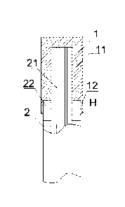
The reference designators in the drawings are described below: 1: aluminum
terminal;
11: first cavity; 12: second cavity; 2: aluminum wire; 21: conductor core 22:
insulation
layer; 3: copper terminal; 31: three-way joint end surface; 32: closed hollow
cavity; 4:
chamfered structure; 5: entrance for the aluminum wire to pass on the copper
terminal; H:
minimum wall thickness.
Detailed Description of the Embodiments
In order to further illustrate the technical solutions used in the present
invention to
realize the above-mentioned objectives and the functions thereof, the specific
embodiments,
structures, features, and functions of the present invention will be described
in detail
hereinafter with reference to the drawings and preferred embodiments. The
details are as
below.
Aluminum terminal structure 1 (with the right-angle structure)
FIG. 1 shows the first structure of the aluminum terminal 1 of the present
invention,
including the insertion cavity for inserting the aluminum wire 2. The
insertion cavity
includes the first cavity 11 with an inner diameter matching an outer diameter
of the
conductor core 21 of the aluminum wire 2, and the second cavity 12 with an
inner diameter
matching an outer diameter of the insulation layer 22 of the aluminum wire 2.
The rear end
of the first cavity 11 is connected to the front end of the second cavity 12.
The minimum
wall thickness H of the insertion cavity is not less than 1/6 times the wall
thickness of the
insulation layer.
During installation, the insulation layer 22 at the front end of the aluminum
wire 2 is
first removed to expose the conductor core 21, and then the aluminum wire 2 is
inserted
into the insertion cavity. It should be ensured that the exposed portion of
the conductor core
21 is located in the first cavity 11, and a part of the remained insulation
layer 22 is located
in the second cavity 12. After that, a pressure of about 30 MPa is applied to
the aluminum
S CA 03042116 2019-04-29
=
terminal 1, so as to crimp and fix the aluminum terminal 1 with the part of
aluminum wire
2 located inside it.
It is concluded from multiple compression tests that with a pressure of 30 MPa
applied to the aluminum terminal 1 at normal atmospheric pressure, if the
minimum wall
thickness of the insertion cavity is set as 1/7, 1/8, 1/9, 1/10, 1/11 or 1/12
times the wall
thickness of the insulation layer of the aluminum wire, obvious cracks
appeared on the
surface of the aluminum terminal of the present invention. While, if the
minimum wall
thickness of the insertion cavity is set as 1/6, 1/5, 1/4, 1/3, 1/2, 1, 2,
3...15, 18, or 20 times
the wall thickness of the insulation layer of the aluminum wire, under the
same pressure, no
crack appeared on the surface of the aluminum terminal 1 of the present
invention.
Therefore, the cases where the aluminum terminal 1 fractures during the
crimping with the
aluminum wire 2 can be effectively reduced when the minimum wall thickness of
the
insertion cavity is set as at least 1/6 times the wall thickness of the
insulation layer.
Meanwhile, if the minimum wall thickness H of the insertion cavity is greater
than or
equal to the threshold value i.e. 1/6 times the wall thickness of the
insulation layer 22, the
mechanical strength of the connection joint between the aluminum terminal 1
and the
aluminum wire 2 can be ensured when the copper-aluminum connector is formed by
the
aluminum terminal 1 and the copper terminal 3, thus further ensuring the
performance of
the electrical connection therebetween.
It should be noted that in the aluminum terminal 1 shown in FIG. 1, the first
cavity 11
and the second cavity 12 are of uniform thickness, and the wall thickness of
the first cavity
11 is greater than the wall thickness of the second cavity 12. Accordingly, in
the present
structure, the minimum wall thickness H of the insertion cavity substantially
denotes the
minimum wall thickness of the second cavity 12 shown in FIG. 1. Obviously, for
the
persons skilled in the art, the minimum wall thickness H of the insertion
cavity should not
be limited to the way shown in FIG. 1 as described above. When the wall
thickness of the
first cavity 11 is equal to the wall thickness of the second cavity 12, the
minimum wall
thickness H of the insertion cavity is the minimum wall thickness of the first
cavity 11 or
the minimum wall thickness of the second cavity 12. Optionally, when the wall
thickness of
the first cavity 11 is smaller than that of the second cavity 12, the minimum
wall thickness
11
CA 03042116 2019-04-29
H of the insertion cavity is the minimum wall thickness of the first cavity
11. Optionally,
when the wall thickness of the first cavity 11 and the wall thickness of the
second cavity 12
are of gradually varying or stepped type, the minimum wall thickness H of the
insertion
cavity should be understood as the one with minimum wall thicknesses in the
first cavity 11
and the second cavity 12, in this case.
Besides the basis that the aluminum terminal I can meet the requirements of
the
essential electrical performance and crimping performance, the manufacturing
cost of the
aluminum terminal 1 can be reduced. As a further improvement of the structure
of the
aluminum terminal 1, the maximum wall thickness of the insertion cavity is not
greater
than 18 times the wall thickness of the insulation layer 22 (i.e., the maximum
wall
thickness of the insertion cavity is at most 18 times the wall thickness of
the insulation
layer 22).
The cross-sections of the first cavity 11 and the second cavity 12 are of
rectangular
shape. The inner diameter of the first cavity 11 is slightly greater than the
outer diameter of
the aluminum conductor core 21. The inner diameter of the second cavity 12 is
slightly
greater than a sum of the diameter of the conductor core 21 and the wall
thickness of the
aluminum wire insulation layer 22.
The conductor core 21 is mainly made of aluminum or aluminum alloy, and the
conductor core 21 may be formed by one core wire, or by twisting multiple core
wires.
In order to improve the electrical conductivity between the aluminum wire 2
and the
aluminum terminal 1, an electrically conductive coating layer (not shown in
the drawings)
for allowing an electrical conduction between the conductor core 21 and the
first cavity 11
is provided between the inner wall of the first cavity 11 and the conductor
core 21. With the
electrically conductive coating layer, not only the electrical contact between
the inner wall
of the first cavity 11 and the conductor core 21 can be improved, but also the
air, moisture
and other impurities between the inner wall and the conductor core 21 can be
eliminated to
avoid oxidization of the conductor core 21 and reduce the resistance between
the conductor
core 21 and the aluminum terminal 1. Meanwhile, the electrically conductive
coating layer
can also avoid the increase of the resistance between the conductor core and
the aluminum
terminal caused by oxidation or other factors as time goes by. The objective
of further
12
CA 03042116 2019-04-29
improving the electrical conductivity performance between the aluminum wire 2
and the
aluminum terminal 1 is therefore achieved.
In order to increase the fluidity of the electrically conductive coating
layer, the
electrically conductive coating layer includes at least 15 wt% of electrically
conductive
portion and at most 85 wt% of carrier portion.
In order to uniformly distribute the electrically conductive portion inside
the
electrically conductive coating layer to ensure the performance of the
electrical
conductivity between the aluminum wire 2 and the aluminum terminal 1, as a
further
improvement of the aluminum terminal structure, the electrically conductive
coating layer
is mainly composed of 30-90 wt% of electrically conductive portion, and 10-70
wt% of
carrier portion.
Specifically, the carrier portion includes a resin matrix and an adhesive. The
carrier
portion further includes one or more of a cross-linking agent, a coupling
agent, and a
dispersing agent. The resin matrix can effectively bond the electrically
conductive portion,
and fill the gap to prevent air, moisture, and impurities from leaving between
the first
cavity 11 and the conductor core 21. The dispersing agent facilitates the
uniform
distribution of the electrically conductive portion. The adhesive improves the
bonding
between the carrier portion and electrically conductive portion. The cross-
linking agent
improves the overall strength and elasticity of the electrically conductive
coating layer. And,
the coupling agent enhances the combination of components of the electrically
conductive
coating layer.
As a first preferred component of the electrically conductive portion of the
aluminum
terminal structure, the electrically conductive portion includes at least one
of gold powder,
silver powder, copper powder, aluminum powder, zinc powder, iron powder,
cadmium
powder, magnesium powder, lithium powder, tin powder, or nickel powder.
The following table shows the test results of the electrical conductivity
performance
of electrically conductive coating layer formed by different kinds of metal
powder with
electrically conductive components of different ratios.
13
I 1
CA 03042116 2019-04-29
,
,
electrically resistivity resistivity resistivity resistivity resistivity
resistivity resistivity
conductive at a ratio at a ratio at a ratio at 57.5% at a
ratio at a ratio at a ratio
component of of of 40% addition of
of 90% of 100%
15%*105 30%*105 *105 level *105 60%*105 *105 *105
(SI m ) ( Q in ) (1-2 m ) (gym) (.0 m ) (fl=m) (S2=m)
Ag 3.98 3.08 2.67 2.00 1.98 1.71
1.65
Cu 4.55 3.97 3.82 3.45 3.35 2.24
1.78
Au 4.57 4.22 3.99 3.77 3.65 2.96
, 2.44
Al 4.96 4.71 4.52 3.96 3.86 3.63
2.73
Mg 6.08 5.97 5.77 5.24 5.12 4.78
4.57
Zn 7.02 6.87 6.63 6.11 5.99 5.61
5.36
Ni
9.01 8.77 8.30 7.98 7.86 7.22 6.93
Cd
9.35 8.98 8.55 8.05 7.94 7.30 6.99
Li
11.37 10.98 10.48 10.27 10.21 9.54 9.48
Fe
11.54 11.21 11.07 10.84 10.75 9.99 9.87
Sn 13.76 13.42 13.07 12.71 12.62 11.92
11.85
As one can see in the above table, for the same kind of metal powder, the
higher the
ratio, the lower the resistivity of the formed electrically conductive coating
layer, and the
better the electrical conductivity performance between the aluminum wire 2 and
the
aluminum terminal 1. In contrast, the lower the ratio of the metal powder, the
higher the
resistivity of the formed electrically conductive coating layer, and the worse
the electrical
conductivity performance between the aluminum wire 2 and the aluminum terminal
1. In
the present table, for the same kind of metal powder, the best electrical
conductivity
performance can be achieved when the electrically conductive coating layer is
formed by
the metal powder at a ratio of 100%, while the worst electrical conductivity
performance
can be achieved when the electrically conductive coating layer is formed by
the metal
powder at a ratio of 15%.
Among different kinds of metal powders, with the same ratio, Al powder, Mg
powder,
Zn powder, Cd powder, Fe powder, Sn powder and Ni powder are cheaper. However,
since
Mg powder is relatively active in air, Fe powder gets oxidized and corroded in
the air easily,
and Cd powder and Sn powder are of relatively low electrical conductivity
performance, so
Al powder, Zn powder, or Ni powder is preferred electrically conductive
component for
14
I
CA 03042116 2019-04-29
reduced manufacturing cost. While, among Ag powder, Cu powder, Au powder, and
Li
powder, the electrical conductivity performance of the Ag powder, the Cu
powder, and the
Au powder is better than that of the above-mentioned metal powders. Although
the Au
powder and Ag powder are chemically stable, they are too expensive to be
suitable for the
situation where a low manufacturing cost is required. Li powder is expensive
while having
a relatively common electrical conductivity performance. Cu powder has a good
electrical
conductivity performance while having a low manufacturing cost. Thus, in the
practical
manufacturing process, one can flexibly adjust the specific composition of the
conductive
component of the electrically conductive coating layer according to the actual
budget. For
example, besides satisfying the requirement for electrical conductivity
performance, the use
of the expensive electrically conductive portion can be appropriately reduced
to save the
manufacturing costs.
As a second preferred component of the electrically conductive portion of the
aluminum terminal structure, the electrically conductive portion is mainly
composed of
graphite powder.
The following table shows the test result of electrical conductivity
performance of the
electrically conductive coating layer formed by graphite powder with
conductive
components of different ratios.
electrically resistivity resistivity resistivity resistivity resistivity
resistivity resistivity
conductive at a ratio at a ratio at a ratio at a ratio
at a ratio at a ratio at a ratio
component of 15% of 30% of 40% of 57.5% of 60% of 90%
of 100%
*103 *103 *10' *103 *103 *103 *103
(5m) (1-1 m) (S2=m) (S2=m) (S2 m) (n=m) (S2 m)
graphite 13.08 11.97 10.11 8.56 8.47 6.97 5.25
As one can see in the above table, the second preferred component of the
electrically
conductive portion of the aluminum terminal structure i.e. graphite powder can
ultimately
form the electrically conductive coating layer with the carrier portion and
achieve the
corresponding electrically conductive effects. Nonetheless, compared with the
above-mentioned first preferred component with the metal powder such as Au
powder, Ag
powder, Cu powder, Al powder, Zn powder, Fe powder, Cd powder, Mg powder, Li
powder,
CA 03042116 2019-04-29
Sn powder, and Ni powder as the electrically conductive portion, the graphite
powder has a
relatively poor electrical conductivity performance. However, the
manufacturing cost of the
electrically conductive portion formed by graphite powder is much lower than
that of the
above-mentioned first preferred component, which can greatly decrease the
manufacturing
cost of the electrically conductive portion.
Aluminum terminal structure 2 (with the chamfered structure)
FIG. 2 shows the second structure of the aluminum terminal of the present
invention,
which is solely different from the first structure shown in FIG. 1 in that the
inner wall of
the connection joint between the first cavity 11 and the second cavity 12 is
of the
chamfered structure 4. The chamfered structure 4 can effectively protect the
aluminum
terminal 1 from obvious cracks when the aluminum terminal 1 is compressed, and
protect
the core wire 21 and insulation layer 22 from indentations or friction
abrasions caused by
the right-angle side as shown in FIG. 1 during compression, so as to avoid the
influence on
product properties.
During installation, the insulation layer 22 at the front end of the aluminum
wire 2 is
first removed to expose the conductor core 21, and then the aluminum wire 2 is
inserted
into the insertion cavity.
Aluminum terminal structure 3 (with the opening)
FIG. 3 shows the third structure of the aluminum terminal in the present
invention,
which is solely different from the second structure shown in Fig. 2 in that
the front end of
the first cavity 11 is provided with an opening. When the copper-aluminum
transition
connector is formed, the conductor core 21 of the aluminum wire 2 can pass
through the
opening and contact the copper terminal 3 to achieve a direct contact with the
copper
terminal 3.
Besides, the present invention further discloses a copper-aluminum transition
connector formed by the above-mentioned aluminum terminal structure. The
specific
structure of the copper-aluminum transition connector will be further
described hereinafter.
Copper-aluminum transition connector structure 1 (with the right-angle
structure and the plane surface)
16
CA 03042116 2019-04-29
FIG. 4 shows the first copper-aluminum transition connector structure in the
present
invention, including the copper terminal 3 and at least one aluminum terminal
1 shown in
FIG. 1. The copper terminal 3 is fixed on the front end of the first cavity 11
of the
aluminum terminal 1. In the first copper-aluminum transition connector
structure, the
preferred quantity of the aluminum terminal 1 is one.
Specifically, the copper terminal 3 is fixed on the front end of the first
cavity 11 by a
friction welding, a resistance welding, a laser welding, an electron beam
welding, or a
pressure welding. Compared with the copper-aluminum transition connector
formed by
using other welding modes, the welding modes used in the present invention can
effectively avoid the galvanic cell reaction between the copper and the
aluminum, so as to
ensure the mechanical properties and electrical properties of the copper-
aluminum
transition connector.
Specifically, the connection surface between the copper terminal 3 and the
front end of
the first cavity 11 is a plane surface. In the welding process, since the end
surfaces of the
copper terminal and the aluminum terminal can be easily aligned, the
implementation of
the welding is easy, and a strong solid joint between the copper terminal and
the aluminum
terminal can be formed with a lower tendency to cause quality problems of
welding beads,
air holes, etc., which not only greatly decreases the defective index and
saves the
manufacturing cost, but also facilitates the improvement of the safety and
reliability of the
copper-aluminum transition connector during use.
Copper-aluminum transition connector structure 2 (with the chamfered
structure and the plane surface)
FIG. 5 shows the second copper-aluminum transition connector structure in the
present invention, including the copper terminal 3 and at least one aluminum
terminal 1
shown in FIG. 2. The copper terminal 3 is fixed on the front end of the first
cavity 11 of the
aluminum terminal 1. In the second copper-aluminum transition connector
structure, the
preferred quantity of the aluminum terminals 1 is one. Specifically, the
copper terminal 3 is
fixed on the front end of the first cavity 11 by the friction welding, the
resistance welding,
the laser welding, the electron beam welding, or the pressure welding.
Compared with the
copper-aluminum transition connector formed by other welding modes, the
welding modes
17
CA 03042116 2019-04-29
used in the present invention can effectively avoid the galvanic cell reaction
between the
copper and the aluminum, so as to ensure the mechanical properties and
electrical
properties of the copper-aluminum transition connector. Specifically, the
connection
surface between the copper terminal 3 and the front end of the first cavity 11
is a plane
surface. In the welding process, since the end surfaces of the copper terminal
and the
aluminum terminal can be easily aligned, the implementation of the welding is
easy, and a
strong solid joint between the copper terminal and the aluminum terminal can
be formed
with a lower tendency to cause quality problems of welding beads, air holes,
etc., which
not only greatly decreases the defective index and saves the manufacturing
cost, but also
facilitates the improvement in the safety and reliability of the copper-
aluminum transition
connector during use.
Copper-aluminum transition connector structure 3 (with the chamfered
structure and the folded surface)
The third copper-aluminum transition connector structure of the present
invention is
solely different from the second copper-aluminum transition connector
structure shown in
FIG. 5 in that the connection surface between the copper terminal 3 and the
front end of the
first cavity 11 is a folded surface. With the folded surface, the effective
contact area
between the copper terminal 3 and the aluminum terminal 1 is greatly
increased, which
ensures the good electrical conductivity performance, enhances the mechanical
properties
of the copper terminal and the aluminum terminal during welding, and reduces
the
resistance at the contact surface of the copper terminal and the aluminum
terminal.
Moreover, in the present copper-aluminum transition connector structure, the
folded
surface is V-shaped (as shown in FIG. 6), inverted V-shaped (as shown in FIG.
7),
trapezoidal (as shown in FIG. 8), or inverted trapezoidal (as shown in FIG.
9). It should be
noted that other than the above-mentioned shapes, the folded surface may be of
any other
folded shapes capable of increasing the effective contact area between the
copper terminal
3 and the aluminum terminal 1
Copper-aluminum transition connector structure 4 (with the opening and the
chamfered structure)
18
CA 03042116 2019-04-29
FIG. 10 shows the fourth copper-aluminum transition connector structure in the
present invention, including the copper terminal 3 and at least one aluminum
terminal 1
shown in FIG. 3. The copper terminal 3 is fixed on the front end of the first
cavity 11 of the
aluminum terminal 1. In the fourth copper-aluminum transition connector
structure, the
preferred quantity of the aluminum terminals 1 is one.
Specifically, the copper terminal 3 is fixed on the front end of the first
cavity 11 by the
friction welding, the resistance welding, the laser welding, the electron beam
welding, or
the pressure welding. Compared with the copper-aluminum transition connector
formed by
using other welding modes, the welding modes used in the present invention can
effectively avoid the galvanic cell reaction between the copper and the
aluminum, so as to
ensure the mechanical properties and electrical properties of the copper-
aluminum
transition connector. Specifically, the connection surface between the copper
terminal 3 and
the outer wall of the front end of the first cavity 11 is a plane surface. In
the welding
process, since the end surfaces of the copper terminal and the aluminum
terminal can be
easily aligned, the implementation of the welding is easy, and a strong solid
joint between
the copper terminal and the aluminum terminal can be formed with a lower
tendency to
cause quality problems of welding beads, air holes, etc., which not only
greatly decreases
the defective index and saves the manufacturing cost, but also facilitates the
improvement
in the safety and reliability of the copper-aluminum transition connector
during use.
Copper-aluminum transition connector structure 5 (with the hollow structure
and the opening)
The main improvement of the fifth copper-aluminum transition connector
structure in
the present invention is to configure the copper terminals 3 in the first,
second, third, and
fourth copper-aluminum transition terminal connector structures with a hollow
structure. In
this way, besides satisfying the essential requirements for the electrically
conductive
performance, the consumption of copper materials can be effectively reduced,
which is not
only helpful in reducing the manufacturing cost of the copper-aluminum
transition
connector, but also in reducing the weight of the copper-aluminum transition
terminal. For
example, the copper terminal 3 of the fourth copper-aluminum transition
connector is
configured with a hollow structure, as shown in FIG. 11, the rear end of the
copper terminal
19
CA 03042116 2019-04-29
3 is further provided with the entrance 5 for the conductor core 21 of the
aluminum wire 2
to get into the interior of the copper terminal 3.
Copper-aluminum transition connector structure 6 (with the hollow structure)
The main improvement of the sixth copper-aluminum transition connector
structure in
the present invention is to configure the copper terminals 3 in the first,
second, third, and
fourth copper-aluminum transition terminal connector structures with a hollow
structure. In
this way, besides satisfying the essential requirements for the electrically
conductive
performance, the consumption of copper materials can be effectively reduced,
which is not
only helpful in reducing the manufacturing cost of the copper-aluminum
transition
connector, but also in reducing the weight of the copper-aluminum transition
terminal. For
example, the copper terminals 3 of the second and fourth copper-aluminum
transition
connectors are configured with a hollow structure, as shown in FIG. 12 and
FIG. 13, the
specific implementation of the hollow structure is to form the closed hollow
cavity 32
inside the copper terminal 3. Preferably, the closed hollow cavity 32 is of a
prism, a
cylinder, a cylinder with an elliptical cross-section, or a cone shape
structure.
Copper-aluminum transition connector structure 7 (with multiple aluminum
terminals and the plane surface)
The seventh copper-aluminum transition connector structure in the present
invention
includes the copper terminal 3 and at least one aluminum terminal 1 shown in
FIG. 1, FIG.
2, or FIG. 3. The copper terminal 3 is fixed on the front end of the first
cavity 11 of the
aluminum terminal I. In the seventh copper-aluminum transition connector
structure, the
preferred quantity of the aluminum terminal 1 is more than two.
Taking the copper terminal 3 and the aluminum terminal 1 shown in FIG. 2 as an
example, as shown in FIG. 14, two aluminum terminals 1 are provided. The
copper
terminal 3 is fixed on the front end of the first cavity 11 by the friction
welding, the
resistance welding, the laser welding, the electron beam welding, or the
pressure welding.
Compared with the copper-aluminum transition connector formed by other welding
modes,
the welding modes used in the present invention can avoid the galvanic cell
reaction
between the copper and the aluminum, so as to ensure the mechanical properties
and
electrical properties of the copper-aluminum transition connector.
CA 03042116 2019-04-29
Further, the connection surfaces between the copper terminal 3 and the front
ends of
the first cavities 11 of the two aluminum terminals 1 are plane surfaces. In
the welding
process, since the end surfaces of the copper terminal and the aluminum
terminal can be
easily aligned, the implementation of the welding is easy, and a strong solid
joint between
the copper terminal and the aluminum terminal can be formed with a lower
tendency to
cause quality problems of welding beads, air holes, etc., which not only
greatly decreases
the defective index and saves the manufacturing cost, but also facilitates the
improvement
of the safety and reliability of the copper-aluminum transition connector
during use.
It should be noted that the quantity of the aluminum terminals 1 of the
copper-aluminum transition connector structure is not limited to two, the
quantity may also
be any positive integer such as three, four, five, etc. One can determine the
quantity of the
aluminum terminal 1 according to the use requirement in practice, so it is
very flexible and
convenient for use.
Further, in the present structure, other than solely using the aluminum
terminals 1
shown in FIG. 1, FIG. 2, or FIG. 3, the aluminum terminal 1 shown in FIG. 1,
FIG. 2 and
FIG. 3 can be arbitrary combined according to the specific quantity of
aluminum terminals
for the copper-aluminum transition connector structure required in practice.
Aluminum-copper transition connector structure 8 (with multiple aluminum
terminals and the folded surface)
The eighth copper-aluminum transition connector structure in the present
invention
includes the copper terminal 3 and at least one aluminum terminal 1 shown in
FIG. 1, FIG.
2 or FIG. 3. The copper terminal 3 is fixed on the front end of the first
cavity 11 of the
aluminum terminal 1. In the eighth copper-aluminum transition connector
structure, the
preferred quantity of the aluminum terminal 1 is more than two.
Specifically, the copper terminal 3 is fixed on the front end of the first
cavity 11 by the
friction welding, the resistance welding, the laser welding, the electron beam
welding, or
the pressure welding.
Specifically, the connection surface between the copper terminal 3 and the
front end of
the first cavity 11 of the aluminum terminal 1 is a folded surface, which
greatly increases
the effective contact area between the copper terminal 3 and the aluminum
terminal 1, and
21
CA 03042116 2019-04-29
ensures a good electrical conductivity performance. Moreover, the mechanical
properties of
the copper terminal and the aluminum terminal during welding is enhanced, and
the
resistance at the contact surface of the copper terminal and the aluminum
terminal is
reduced.
Further, in the present copper-aluminum transition connector structure, the
folded
surface is V-shaped or inverted V-shaped. Alternatively, as shown in FIG. 15,
the folded
surface is of trapezoidal shape or inverted trapezoidal shape. Alternatively,
as shown in FIG.
16, the folded surface is of an irregular shape. It should be noted that other
than the
aforementioned shapes, the folded surface may be any other folded shapes
capable of
increasing the effective contact area between the copper terminal 3 and the
aluminum
terminal 1. Further, the quantity of the aluminum terminals 1 of the copper-
aluminum
transition connector structure is not limited to two, the quantity may also by
any positive
integer such as three, four, five, etc. One can determine the quantity of the
aluminum
terminal according to the use requirement in practice, so it is very flexible
and convenient
for use. Further, other than solely using the aluminum terminals 1 shown in
FIG. 1, FIG. 2,
or FIG. 3, the aluminum terminal 1 shown in FIG. 1, FIG. 2 and FIG. 3 can be
arbitrary
combined according to the specific quantity of aluminum terminals for the
copper-aluminum transition connector structure required in practice.
Aluminum-copper transition connector structure 9 (with multiple aluminum
terminals, the plane surface, integrated aluminum terminals)
FIG. 17 shows the ninth copper-aluminum transition connector structure in the
present
invention, which is solely different from the seventh copper-aluminum
transition connector
structure shown in FIG. 14 in that the aluminum terminals 1 are arranged in
one row along
the horizontal direction, and the side walls of the adjacent aluminum
terminals 1 are fixedly
connected. Consequently, the two or more aluminum terminals 1 can be welded to
the
copper terminals 3 at one time without the need of welding the multiple
aluminum
terminals one by one, which greatly improves the assembling efficiency.
In the present structure, the preferred quantity of the aluminum terminals 1
is three. It
should be noted that the quantity of the aluminum terminals 1 of the copper-
aluminum
transition connector structure is not limited to three, it may also be any
positive integer
22
CA 03042116 2019-04-29
such as two, four, five, etc. One can determine the quantity of the aluminum
terminal 1
according to the use requirement in practice, so it is very flexible and
convenient for use.
Further, other than solely using the aluminum terminals 1 shown in FIG. 1,
FIG. 2, or FIG.
3, the aluminum terminal 1 shown in FIG. 1, FIG. 2 and FIG. 3 can be arbitrary
combined
according to the specific quantity of aluminum terminals for the copper-
aluminum
transition connector structure required in practice.
Further, in the copper-aluminum transition connector structure, the connection
surface
between the copper terminal 3 and the front ends of the first cavities 11 of
the aluminum
terminals 1 is not limited to the plane surface shown in FIG. 17, it may also
be the folded
surface shown in FIG. 15 and FIG. 16.
Aluminum-copper transition connector structure 10 (with multiple aluminum
terminals, the plane surface, separated aluminum terminals)
FIG. 18 shows the tenth copper-aluminum transition connector structure of the
present
invention which is solely different from the ninth copper-aluminum transition
connector
structure shown in FIG. 17 in that the aluminum terminals 1 are arranged in
one row along
the horizontal direction, and the adjacent aluminum terminals 1 are separated
from each
other.
Aluminum-copper transition connector structure 11 (with multiple aluminum
terminals, the plane surface, partially separated aluminum terminals)
FIG. 19 shows the eleventh copper-aluminum transition connector structure of
the
present invention, which is characterized in that the ninth copper-aluminum
transition
connector structure shown in FIG. 17 and the tenth copper-aluminum transition
connector
structure shown in FIG. 18 are combined. In detail, the aluminum terminals 1
are arranged
in one row along the horizontal direction, the side walls of at least two
aluminum terminals
are connected to form an integrated structure, the other aluminum terminals 1
are separated
from each other, and the other aluminum terminals 1 are separated from the
integration.
In the present structure, the preferred quantity of the aluminum terminals 1
is three. It
should be noted that the quantity of the aluminum terminals 1 of the copper-
aluminum
transition connector structure is not limited to three, it may also be any
positive integer
such as four, five, etc. One can determine the quantity of the aluminum
terminal 1
23
I 1
. CA 03042116 2019-04-29
according to the use requirement in practice, so it is very flexible and
convenient for use.
Further, other than solely using the aluminum terminals 1 shown in FIG. 1,
FIG. 2, or FIG.
3, the aluminum terminal 1 shown in FIG. 1, FIG. 2 and FIG. 3 can be arbitrary
combined
according to the specific quantity of aluminum terminals for the copper-
aluminum
transition connector structure required in practice.
Copper-aluminum transition connector structure 12 (with the three-way
structure)
The main improvement of the twelfth copper-aluminum transition connector
structure
in the present invention is to configure the copper terminal 3 as a three-way
joint. As
shown in FIG. 20, the three-way joint includes the three end surfaces 31. The
quantity of
the aluminum terminals 1 is three. The front ends of the first cavities 11 of
the three
aluminum terminals respectively correspond to the three end surfaces 31 of the
three-way
joint, and the front end of each first cavity 11 is fixedly connected to the
corresponding end
surface 31.
In this case, besides effectively reducing the consumption of the copper
material, the
electrical connection among the three aluminum terminals 1 is realized, which
not only
reduces the manufacturing cost of the copper-aluminum transition connector,
but also
reduces the weight of the copper-aluminum transition terminal.
In order to simplify the three-way structure and reduce the manufacturing cost
of the
copper-aluminum transition connector, the three-way structure in the
embodiment is
preferably a three-way pipe joint.
The above-mentioned embodiments are merely preferred embodiments of the
present
invention, and it is improper to use these embodiments to limit the scope of
the present
invention. Any immaterial modifications and substitutions made by those
skilled in the art
based on the present invention should be considered as falling within the
scope of the
present invention.
24
I