Note : Les descriptions sont présentées dans la langue officielle dans laquelle elles ont été soumises.
CA 03042754 2019-05-03
1 WO/2018/087480
Heat Exchanger
TECHNICAL FIELD
The present invention relates to heat exchangers, in particular for
a turbine engine.
STATE OF THE ART
A turbine engine comprises a gas generator comprising, for
example, from upstream to downstream in the gas flow direction, one or more
compressor stages, a combustion chamber, one or more turbine stages, and a
nozzle for ejecting exhaust gases.
A heat exchanger is installed in a turbine engine to make it
possible for thermal energy transfer from one fluid to another.
Such a heat exchanger is, for example, used to transfer thermal
energy from hot exhaust gases to a gas intended to be introduced upstream of
the combustion chamber, favouring, in particular, the fuel consumption of the
turbine engine. This heat exchanger can also be used to cool the lubricant
(for
example, oil) of the different means for guiding the rotors of the gas
generator.
Such an exchanger is, for example, obtained by additive
manufacturing by selectively melting on powder beds commonly designated by
SLM (Selective Laser Melting). The SLM additive manufacturing principle is
based on the melting of thin two-dimensional (2D) layers of powder (metal,
plastic, ceramic, etc.) using a high-power laser. SLM technology has the
advantage of making it possible to produce parts having complex geometric
shapes and good mechanical characteristics.
With an equal aerothermal performance, heat exchangers with fins
are particularly used in turbine engines, in particular because of their low
mass.
Such a heat exchanger, between a first fluid (for example, hot
exhaust gases) flowing in a longitudinal direction X and a second fluid (for
example, air), comprises for example, two parallel plates distant from one
another, so as to define a circulation passage for the first fluid and a
plurality of
rows of fins arranged perpendicularly between the plates.
CA 03042754 2019-05-03
2 WO/2018/087480
More specifically, the rows of fins extend longitudinally. Each fin is
delimited longitudinally by a leading edge and a trailing edge perpendicular
to
the plates.
Such an architecture has, in particular, the disadvantage of
leading to a significant loss of mechanical energy from the first fluid,
partially
due to the presence of a recirculation region in the flow at the level of each
of
the leading edges of the fins. This recirculation area is all the more
significant,
because of the variation of the cross-sections for the passage of the first
fluid,
which cause local accelerations.
Furthermore, by SLM manufacturing, in a vertical
orientation (plates and fins perpendicular to the construction support), such
an
architecture does not make it possible to respect the dimensional and
geometric
tolerances required from manufacturing. Indeed, the melting of an overhanging
layer, of which the normal is parallel with the direction of adding layers,
poses
production difficulties, in particular due to the fact that only the non-
melted
powder serves as a support during the melting of such an overhanging layer.
The prior art also comprises documents WO-A2-2010/098666 and
CN-A-104776736.
The aim of the present invention is thus to propose, a heat
exchanger, with an equal mass, having improved aerothermal characteristics,
and respecting the desired dimensional and geometric tolerances, when it is
obtained by additive manufacturing by selective melting on powder beds.
DESCRIPTION OF THE INVENTION
To this end, the invention proposes a heat exchanger between a
first fluid flowing in a longitudinal direction X and a second fluid, said
exchanger
comprising:
- two parallel plates distant from one another so as to define a
circulation passage of said first fluid;
- at least one first and one second row of fins arranged
perpendicularly between said plates, said first and second rows extending
longitudinally, the fins of said first row being arranged, preferably in
staggered
rows with respect to the fins of said second row, each fin being delimited
longitudinally by a first edge and a second edge, said first edge comprising
at
each of the ends thereof, a region of connection with the corresponding plate;
CA 03042754 2019-05-03
, .
3
WO/2018/087480
characterised in that said regions of connection of said first edge
are respectively inclined by an angle A and an angle B with respect to a
normal
N to the plates in a plane P perpendicular to said plates and parallel with
the
direction X, said first edge and said second edge of each of the fins having
an
identical profile in said plane P.
Such geometric characteristics associated with the fins make it
possible, with an equal mass, not only to significantly improve the
aerothermal
performances of the exchanger, but also to respect the desired dimensional and
geometric tolerances, when it is obtained by additive manufacturing by
selective
melting on powder beds.
Indeed, on the one hand, such geometric characteristics make it
possible to significantly reduce the recirculation region in the flow at the
level of
each of the leading edges (first edge or second edge according to the
direction
of the flow) of the fins, and consequently, to reduce the mechanical energy
losses. This reduction is all the more significant, due to there being no
variations in the cross-sections for the passage of the first fluid. In
comparison,
with respect to the heat exchangers of the prior art, it is estimated that the
reduction of the charge losses is around 15%.
On the other hand, for SLM manufacturing, by positioning the
hollow edge on the side of the construction support if necessary, the regions
of
connection respectively constitute a first and a second primer for
manufacturing
the fin. Thus, during manufacturing, there is no overhang layer to melt and,
in
other words, the non-melted powder is not used as a support, favouring
compliance with the required dimensional and geometric tolerances.
The exchanger according to the invention can comprise one or
more of the following characteristics, taken individually from one another, or
combined with one another:
- the angle A is equal to the angle B;
- the angle A and/or the angle B is greater than 40 , and
preferably greater than or equal to 45 ;
- in the plane P, more than 90% of the length of the first edge is
inclined with respect to the normal N, and preferably more than 95%;
CA 03042754 2019-05-03
4 WO/2018/087480
- said first edge comprises at least one rectilinear section inclined
with respect to the normal N and/or at least one circular section and/or at
least
one elliptic section;
- said first edge comprises two rectilinear sections inclined with
respect to the normal N and having concurrent directions;
- the fins are spaced longitudinally by a constant amount.
The invention has as a second object, a method for producing an
exchanger such as described above, wherein it comprises a step of producing
said exchanger by additive manufacturing by selective melting on powder beds
along a manufacturing axis Z parallel with said longitudinal direction X.
Alternatively, said fins each comprise a first hollow edge and a
second protruding edge, the exchanger being manufactured on a construction
support, said first hollow edge being oriented on the side of said support.
The invention has as a third object, a turbine engine comprising a
heat exchanger such as described above.
DESCRIPTION OF THE FIGURES
The invention will be best understood, and other details,
characteristics and advantages of the invention will appear more clearly upon
reading the following description made by way of a non-limiting example and
with reference to the appended drawings, in which:
- figures 1 and 2 are perspective views of a heat exchanger (with
two stages) according to the invention, each stage comprising two plates and a
plurality of rows of fins arranged between the plates, according to a first
embodiment;
- figure 3 is a detailed view of a fin of the heat exchanger of
figures 1 and 2, in a plane P;
- figure 4 is a perspective view of a heat exchanger, according to a
second embodiment;
- figure 5 is a detailed view of a fin of the heat exchanger of
figure 4, in a plane P;
- figure 6 is a schematic view of a machine for producing an
exchanger (or an exchanger stage) according to the invention, by additive
manufacturing;
CA 03042754 2019-05-03
WO/2018/087480
- figures 7 to 10 are detailed views, in a plane P, similar to those of
figures 3 to 5, and illustrate embodiment variants of the fins according to
the
invention.
DETAILED DESCRIPTION
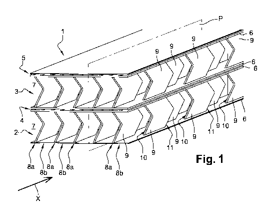
In figures 1 and 2, a heat exchanger 1 between a first fluid (for
example, hot exhaust gases) flowing in a longitudinal direction X and a second
fluid (for example, air) is represented.
More specifically, the exchanger 1 is staged, namely a first and a
second stage 2, 3 for circulating the first fluid. A first path 4 for
circulating the
second fluid is arranged between the first and second stages 2, 3 (inter-stage
circulation path). A second path 5 for circulating the second fluid (not
represented in figure 2) is arranged on the free side of the second stage 3.
The example illustrated is in no way limiting, according to needs,
the exchanger 1 could have a number N of stages, each defining a passage for
circulating the first fluid, two adjacent stages being separated by a path for
circulating the second fluid.
It must be noted, that the flow of the first fluid in the longitudinal
direction X can be from upstream to downstream (such as illustrated in figure
1)
or from downstream to upstream.
In the heat exchanger 1, there is no mixture between the first and
the second fluid.
Each stage 2, 3 of the exchanger 1 comprises two parallel plates 6
distant from one another, so as to define a passage 7 for circulating the
first
fluid and a plurality of rows 8a, 8b (in this case, ten) of heat-conductive
fins 9
arranged perpendicularly between said plates 6.
More specifically, the rows 8a, 8b extend longitudinally (in the
direction X). The fins 9 of two adjacent rows 8a, 8b are arranged in staggered
rows. Each fin 9 is delimited longitudinally by a first edge 10 and a second
edge 11, the first edge 10 comprises, at each of the ends thereof, a region of
connection 12a, 12b with the corresponding plate 6.
The regions of connection 12a, 12b of the first edge 10 are
respectively inclined by an angle A and by an angle B with respect to a normal
N to the plates 6, in a plane P perpendicular to the plates 6 and parallel
with the
CA 03042754 2019-05-03
6 WO/2018/087480
direction X. The first edge 10 and the second edge 11 of each of the fins 9
have
an identical profile, in the plane P.
According to the embodiment illustrated in figures 1
to 2 (respectively on the embodiment of figure 4), the fins 9 are identical
(i.e.
they have the same geometric and dimensional characteristics) and spaced
longitudinally by a constant amount (or clearance). On one same row 8a, 8b,
two consecutive fins 9 are spaced by an interval equal to one fin 9 (and more
specifically, to the longitudinal dimension of one fin 9).
The term "staggered-row arrangement", means a repetitive
arrangement, row by row, where in one row out of two, the fins 9 are offset by
half a step with respect to the adjacent rows.
In a variant, the spacing could be variable or the exchanger 1
could be divided longitudinally into portions, each portion having its own
spacing.
In a variant, the fins 9 of two adjacent rows 8a, 8b could be
partially covered, in the plane P.
According to the invention, in a plane P, when the region of
connection 12a is rectilinear, the angle A (respectively for the angle B)
corresponds to the angle between the region of connection 12a and the normal
N.
According to the invention, in a plane P, when the region of
connection 12a (respectively region of connection 12b) is curved, the angle
A (respectively for the angle B) corresponds to the angle between the tangent
T
to the region of connection 12a (at the level of a point located in the
proximity of
the corresponding plate 6) and the normal N.
Advantageously, in a plane P, more than 90% of the length of the
first edge 10 (respectively of the second edge 11) is inclined with respect to
the
normal N, and preferably more than 95%.
The angle A and/or the angle B is greater than 40 , and preferably
greater than or equal to 45 .
According to a first embodiment illustrated in figures 1 to 3, for
each fin 9, in a plane P, the first edge 10 (respectively the second edge 11)
comprises two rectilinear sections 13 inclined with respect to the normal N
and
having concurrent directions.
CA 03042754 2019-05-03
7 WO/2018/087480
More specifically, the first edge 10 has a general V shape. Each of
the rectilinear sections 13 converges from the corresponding plate 6. The two
rectilinear sections 13 are sealed by a fillet 14 (concave shape). The angle A
is
equal to the angle B, and is equal to 45 .
According to a second embodiment illustrated in figures 4 and 5,
for each fin 9, in a plane P, the first edge 10 comprises one single
rectilinear
section 15 inclined with respect to the normal N. Each fin 9 thus has a
parallelogram shape. The angle A is equal to the angle B, and is equal to 45 .
Figure 6 shows a machine 100 for manufacturing a heat
exchanger 1 or a stage 2, 3 of the exchanger 1 by additive manufacturing, and
in particular by selective melting of powder layers 160 with a high-energy
beam 195.
The heat exchanger 1 (or the stage 2, 3 of the exchanger 1) is
advantageously manufactured along a manufacturing axis Z parallel with the
longitudinal direction X (plates 6 and fins 9 perpendicular to the
construction
support 180) (see figures 3 and 5).
The machine 100 comprises a feed tray 170 containing the
powder 160 (metal in the present case), a roller 130 to decant this powder 160
from the tray 170 and to spread a first layer 110 of this powder 160 on a
construction support 180 mobile in translation along the manufacturing axis
Z (the support 180 can be, for example, a plate, a portion of another part or
a
gate).
The machine 100 also comprises a recycling tray 140 to recover
the excess powder 160 after spreading the layer of powder with the roller 130
on the construction support 180.
The machine 100 further comprises a laser beam 195
generator 190, and a steering system 150 capable of directing this beam 195
over all of the construction support 180, so as to melt the desired powder
portions 160. The shaping of the laser beam 195 and the variation in the
diameter thereof over the focal plane are done respectively by means of a beam
dilator 152 and a focussing system 154, all constituting the optical system.
More specifically, the steering system 150 comprises, for example,
at least one mirror 155 that can be oriented, on which the laser beam 195 is
reflected before reaching the powder layer 160. The angular position of this
CA 03042754 2019-05-03
8 WO/2018/087480
mirror 155 is controlled, for example, by a galvanometric head such that the
laser beam 195 scans the desired portions of the first layer 110 of powder
160,
according to a pre-established profile.
The heat exchanger 1 (or the stage 2, 3 of the exchanger 1) is
manufactured along the manufacturing axis Z (parallel with the direction
X) (plates 6 and fins 9 perpendicular to the construction support 180). Such
as
illustrated in figure 3, when the profile of the fins 9 comprises a hollow
edge 10
and a protruding edge 11, the hollow edges 10 must be oriented on the side of
the construction plate in order to avoid any overhanging layer from being
melted.
The manufacturing of an exchanger 1 (or stage 2, 3 of an
exchanger 1) using the machine 100 comprises the following steps.
A first layer 110 of powder 160 is deposited on the construction
support 180 using the roller 130. At least one portion of this first layer 110
of
powder 160 is brought to a temperature greater than the melting temperature of
this powder 160 by the laser beam 195, such that the powder particles 160 of
this portion of the first layer 110 are melted and form a first cordon 115
from a
single part, secured to the construction support 180.
Then, the support 180 is lowered from a height corresponding to
the thickness already defined from the first layer 110. A second layer 120 of
powder 160 is deposited on the first layer 110 and on this first cordon 115,
then
at least one portion located partially or completely above this first cordon
115 is
heated by exposure to the laser beam 195, such that the powder particles 160
of this portion of the second layer 120 are melted, with at least one portion
of
the first element 115, and form a second cordon 125. The assembly of these
two cordons 115 and 125 forms a block made of a single part.
The process of constructing the part is then followed layer by
layer, by adding additional layers of powder 160 on the assembly already
formed. The scanning with the beam 195 makes it possible to construct each
layer by giving it a shape according to the geometry of the part to be
produced.
The three-dimensional (3D) exchanger 1 (or the stage 2, 3 of the
exchanger 1) is therefore obtained by a superposition of two-dimensional (2D)
layers, along the manufacturing axis Z.
CA 03042754 2019-05-03
9 WO/2018/087480
The powder 160 is advantageously made of a material having a
good thermal conductivity in order to maximise the thermal transfers between
the first fluid and the second fluid, and thus increase the efficiency of the
heat
exchanger 1.
Advantageously, the powder 160 is metal and preferably steel or
metal alloy, for example nickel-based.
Figures 7 to 10 illustrate different embodiments of the invention.
According to a first embodiment represented in figure 7, for each
fin 9, in a plane P, the first edge 10 comprises one single concave elliptical
section 16. The elliptical section 16 corresponds to a section of a
construction
ellipsis 17 (represented by a dotted line), of which the centre is located
equidistantly from the two plates 6, offset longitudinally with respect to the
regions of connection 12a, 12b, the construction ellipsis 17 being tangent to
the
plates 6. The elliptical section 16 has an angle at the centre, of slightly
less
than 180 .
According to a second embodiment represented in figure 8, for
each fin 9, in a plane P, the first edge 10 comprises two convex elliptical
sections 18.
More specifically, each of the elliptical sections 18 converges from
the corresponding plate 6. The two elliptical sections 18 are sealed by a
fillet 19 (concave shape) so as to form a first and a second inflexion point
I, J.
The elliptical sections 18 each correspond to a section of a construction
ellipsis 20 (represented as a dotted line) having an angle at the centre
substantially equal to 90 (quarter of an ellipsis). These construction
ellipses 20
are superposed, aligned and have the same dimensional characteristics.
According to a third embodiment represented in figure 9, for each
fin 9, in a plane P, the first edge 10 comprises one single concave elliptical
section 21. The elliptical section 21 corresponds to an elliptical section
having
an angle at the centre substantially equal to 90 (quarter of an ellipsis) and
is
connected to one of the plates 6 via a fillet 22 (concave shape).
According to a fourth embodiment represented in figure 10, for
each fin 9, in a plane P, the first edge 10 comprises one single convex
circular
section 23. The circular section 23 corresponds to a circular arc having an
angle
CA 03042754 2019-05-03
. .
WO/2018/087480
at the centre substantially equal to 900 (quarter of a circle) and is
connected to
the plates 6 via a fillet 24 (concave shape).
To improve the mechanical and aerothermal performance, the
sharp edges can be replaced by fillets (concave shape) or curves (convex
shape).
The different embodiments illustrated of the fins 9 are not limiting.
Indeed, according to the invention, the first edge 10 can contain one or more
rectilinear sections and/or one or more curved sections, however,
advantageously, more than 90% of the length of the first edge 10 (in a plane
P) (and respectively of the second edge 11) is inclined with respect to the
normal N, and preferably 95%.