Note : Les descriptions sont présentées dans la langue officielle dans laquelle elles ont été soumises.
CA 03043505 2019-05-10
WO 2018/091462
PCT/EP2017/079198
1
Device for measuring the circumference of an obiect
The present invention relates to a device for measuring the circumference
of an object, in particular the circumference of a limb, comprising:
- a winder of a
flexible measuring element arranged to be affixed and form
a loop around the said object, in particular around the said limb, when
the said measuring element is in a measuring position, the said reel
having at least one wall and an exit opening arranged to allow the exit of
at least one unwound portion of the said measuring element, the said at
io least one
unwound portion of the said measuring element being defined
between the said exit opening and a distal end of the said measuring
element, the said distal end of the said measuring element being
equipped with a connecting element that abuts against the said exit
opening, when the said measuring element is in the rest position, and
- connecting means of the said connecting element of the said distal end
of the said measuring element, the said connecting means being located
at a distance d from the said exit opening and the said connecting means
being less than or equal to 4 cm, preferably less than or equal to 3 cm,
preferably less than or equal to 2 cm, and more preferably less than or
equal to 1 cm, and most preferably equal to zero.
Such a device is used in particular for measuring the circumference
of the arms, thighs and legs of a patient, the measuring element typically
having graduations. To measure the circumference of a limb, it is first
necessary to unwind at least a portion of the measuring element from the
winder outlet and then place this unwound portion around the limb, this prior
to or after the distal end of the unwound measuring element is connected to
a connecting means. Once this connection is established, the operator must
ensure that the unwound portion of the measuring element follows the
contours of the limb and a reading of the limb circumference can then be
achieved using the graduations.
Note that the devices of the prior art generally have a curvature
facilitating the placing of the device against a limb to conform to the shape.
CA 03043505 2019-05-10
WO 2018/091462
PCT/EP2017/079198
2
However, each device has its own curvature and is therefore more or less
suited to a given limb of a specific diameter. But, when the curvature of the
limb is different and especially less than that of the measuring device
according to the state of the art, measurement errors of a few centimetres
and a significant loss of accuracy are noted.
Circumference measurements are also currently performed with
simple measuring devices corresponding to tape measures. However, the
use of a tape measure is particularly restrictive because the operator has to
hold it in place such that it overlaps at least partially in order to
determine a
ic circumference and he needs to be careful not to exert too much traction
on
the tape measure, and must do all this while remaining motionless so as not
to distort the measurement.
A measurement of the circumference of limbs such as an arm or leg
is especially recommended in the assessment and monitoring of the
physiotherapy treatment, for example for the treatment of lymphedema, i.e.
the swelling of a part of the body following an accumulation of lymphatic
fluid
in the interstitial tissue. These swellings mainly affect the upper and lower
limbs such as, for example, the fingers, toes, arms, feet, legs, thighs and
hands, but can also occur in other parts of the body such as the neck,
abdomen, back or breasts.
In order to determine to what extent the lymphedema (primary or
secondary) must be treated, it is necessary to monitor changes. For
example, if we consider secondary lymphedema of the upper limbs, clinical
practice guidelines for the care and treatment of breast cancer (Clinical
practice guidelines for the care and treatment of breast cancer, Canadian
Medical Association Journal) recommends measuring the brachial
circumference at four points: the metacarpal-phalangeal joints, wrists, 10 cm
below and 15 cm above the lateral epicondyles (elbow). It is considered that
a difference of more than 2 cm in the circumference between two
measurements at one of these four measurement points justifies the
treatment of lymphedema. A difference of more than 2 cm in the
circumference between a limb (e.g. the right arm) with lymphedema and a
CA 03043505 2019-05-10
WO 2018/091462
PCT/EP2017/079198
3
corresponding limb (e.g. the left arm) not having lymphedema also indicates
that it is appropriate to treat this swelling.
It is therefore necessary to have a measuring device or instrument
that can measure the circumference of limbs occasionally and at the same
place in order to be able to decide whether treatment of lymphedema is
applicable or not. It is particularly necessary to have a measurement tool
that allows for accurate and reliable measurement since the margin of error
must be small and only of a few millimetres, preferably in the range of less
than 5 millimetres and more preferably in the range of less than 2
io millimetres.
A measurement of the circumference of limbs is also indicated to
record a decrease in the volume of skeletal muscles and monitor any
changes. Such a decrease in muscle volume (or loss of muscle mass) may,
for example, be due to muscle wasting (atrophy and I or disappearance of
is the striated
muscle fibre), sarcopenia (geriatric syndrome) or myopathy
(neuro-muscular disease). These conditions require monitoring and
especially physiotherapy treatment, in which an accurate measurement of
the circumference of the limb with the muscle in question is essential. Again,
the change in the circumference of the limb can be monitored by comparing
20 two
measurements taken at the same location after a predetermined period
of time or by comparing the circumferences of a "healthy" limb and a
corresponding limb affected by a decrease in muscle volume (loss of muscle
mass).
A measurement of the circumference of limbs is also indicated to
25 record a
decrease in volume when following a diet and during anti-cellulite
treatments, during which the limb is expected to become thinner.
A measurement of the circumference of limbs is also indicated to
record a change in volume when following a body-building programme
where an increase in muscle volume is expected or desired.
30 Finally, a
measurement of the circumference of limbs is also
indicated to monitor the growth of infants, which involves taking
CA 03043505 2019-05-10
WO 2018/091462
PCT/EP2017/079198
4
circumference measurements of very thin and very small limbs, where no
measurement error can be tolerated.
It is understood that any other condition or pathology involving a
change in the circumference of a limb falls within the scope of the present
invention.
Unfortunately, with a measuring device such as the one described
above and used currently, it appears that the measurements are accurate
and reliable only for certain objects/limbs of average circumferences. On the
contrary, these measurements are totally biased when objects/limbs have
io very small
circumferences (e.g. fingers, toes, wrists and ankles) or,
conversely, very large circumferences (e.g. the abdomen). For example, this
totally biased measurement problem is encountered while measuring the
circumference of very thin limbs of infants or while measuring the
circumference of fingers.
Another problem encountered with such a device, as is currently
used, is that the shape and curvature of the objects/limbs have a direct
impact on measurement accuracy. For example, while a correct and
accurate measurement can be noted at the wrist of an adult when the
measuring device is placed flat just behind the head of the ulna (like a
watch), this will not be the case if the same measuring device is offset by
900 to the right or left. In fact, when the object/limb does not have a
perfectly
cylindrical shape (which is the case of most limbs), such a measuring device
according to the prior art, which nevertheless has a curvature defined
between the opening and the connecting means, completely lacks in
precision and the measurements are not reproducible. This is even more
pronounced when the limb in question has a curvature that differs from that
of the measuring element.
Moreover, since operators are not the same, measurements taken
with such a measuring device are not reproducible; in the example of the
wrist stated above, if the operator positions the device one way rather than
another, entirely different measurements will be obtained.
CA 03043505 2019-05-10
WO 2018/091462
PCT/EP2017/079198
It follows from all this that a currently used device is not versatile
since it does not allow to obtain accurate and reproducible measurements
of circumferences for all types of objects/limbs, each inevitably having a
different circumference and curvature. Furthermore, as noted above, there
5 are major
problems of reproducibility of measurements, especially when
different operators perform the circumference measurements on the same
object/limb.
Document EP 1 439 370 proposes a measuring device in which the
exit opening is equipped with a connecting means in which the end of the
measuring element can be inserted when it is wrapped around the limb to
be measured.
Unfortunately, such a device is not reliable and not very practical,
since the patient's skin can get trapped in the connecting means at the exit
opening. This is particularly uncomfortable for the user. The accuracy of the
measurement is also affected.
The invention aims to overcome the disadvantages of the prior art
by providing a device for measuring the circumference of an object,
particularly the circumference of a limb, which can ensure rapid, reliable,
accurate and reproducible measurements for any type of object/limb,
regardless of whether the latter has a small circumference (wrists, ankles,
fingers, etc.) or a large circumference (abdomen, etc.) or one particular type
of curvature/shape (e.g. due to the presence of a protuberance such as the
wrist or ankle) instead of another.
Furthermore, the invention also aims to provide a measuring device
of a reasonable size that is handy, light and compact so that it can be easily
stowed in the pocket of a garment, which is also an advantage in the medical
field where professionals in the health field have to keep moving from room
to room or from one cabinet to another to examine their patients, and hence
they frequently store their equipment in the pockets of their work smock.
In this sense, the present invention intends to provide a measuring
device that is versatile and that is not limited to specific circumferences
and/or objects or individual limbs, by ensuring that reproducible and reliable
CA 03043505 2019-05-10
WO 2018/091462
PCT/EP2017/079198
6
measurements are possible at a given location of the object/limb,
irrespective of the positioning of the measuring device and regardless of the
operator.
To solve this problem, the invention defines a device for measuring
the circumference of an object as indicated at the beginning, characterized
in that the said connecting means is located on the said at least one wall of
the said winder, is adjacent to the said exit opening, is in the form of a
protuberance that extends in the direction of the said distal end of the said
measuring element, and is designed to receive the connecting element in a
stationary manner, when the said measuring element is in the measuring
position.
Unexpectedly in the context of this invention, it was determined that
the presence of the connecting means allows guaranteeing the accuracy
and ease of taking measurements, regardless of the type or shape of the
object whose circumference is to be measured. Thus, the device according
to the invention is resistant, durable and allows measuring the circumference
of an object/limb rapidly, accurately, reproducibly and reliably, regardless
of
whether or not this object/limb has curvatures and/or protuberances, and
regardless of the operator taking the measurement of the circumference.
Advantageously, the said distance d defined between the said exit
opening and the said connecting means is equal to 5 mm, preferably equal
to 4 mm, preferably equal to 3 mm, more preferably equal to 2 mm, and most
preferably equal to 1 mm.
According to a preferred embodiment, the distance d is equal to
zero, which means that the connecting means is joined and is therefore in
contact with the exit opening of the winder. Such a relative positioning
between the connecting means and the winder exit opening especially
allows avoiding any errors and bias in the measurement of a circumference
of an object/limb. For example, since the exit opening is delimited by four
walls, it is planned according to the invention for the connecting means to
be placed in direct contact with one of these walls, such that the distance d
is zero or at least only a few millimetres at the most.
CA 03043505 2019-05-10
WO 2018/091462
PCT/EP2017/079198
7
The terms "flexible", "flexible measuring element" or "measuring
element made of a flexible material", within the meaning of the present
invention, refer to a measuring element whose flexibility allows it to
follow/surround the surface of the object or limb whose circumference is to
be measured, closely and in contact with the said object/limb.
Preferably, according to the invention, the said loop formed around
the said object, in particular around the said limb, is placed in a single
plane
passing through a median longitudinal axis defined along the said measuring
element. Such positioning of the loop and thus the unwound portion of the
measuring element according to the invention allows ensuring optimum
accuracy of the measurement of the circumference. Indeed, any bias is
minimized since the loop is positioned in a single plane.
Advantageously, according to the invention, the said winder of the
said device is a spring winder optionally equipped with a locking system
and/or a rewinding system of the said measuring element. During the use of
a measuring device according to the invention, the locking system
advantageously makes it possible, after unwinding at least a portion of the
measuring element, to lock the latter in order to facilitate the positioning
of
the measuring element around the object/limb.
Furthermore, following the positioning of the measuring element
around the object/limb and after connecting the distal portion of the
measuring element to the connecting means according to the invention, the
rewinding system of the measuring element allows an automatic and proper
placement of the measuring element around the object/limb whose
circumference is to be measured. Indeed, since the unwound portion of the
measuring element is usually longer than the circumference to be actually
measured, for reasons of ease of placement of the measuring device, it then
becomes necessary to ensure that the measuring element closely follows
the contour of the object/limb; this may be achieved according to the
invention by a (automatic) rewinding system of the measuring element, in
particular for the unwound portion of the measuring element. Of course, any
type of suitable winder can fall within the scope of the present invention.
CA 03043505 2019-05-10
WO 2018/091462
PCT/EP2017/079198
8
Advantageously, the said measuring device according to the
invention comprises at least one tension sensor housed within the said
winder to detect that the measuring element is tensed, in order to be able to
measure the tension; the said tension is preferably linked to a weight of
between 5 and 3000 g, preferably between 15 and 1500 g, more preferably
between 15 and 1000 g, advantageously between 15 and 500 g, more
advantageously between 15 and 150 g, and/or also comprising a motor
housed in the winder in order to apply sufficient tension for a weight that is
within one of the aforementioned ranges.
Preferably, according to the invention, the said measuring element
of the said device may or may not have graduations. According to the
present invention, it is planned, according to a first embodiment, that the
measurement of the circumference is detected visually through these
graduations on the measuring element. According to a second embodiment,
this reading can be performed using a dial that digitally displays the
measured circumference value, in which case graduations are not
necessary.
Preferably, according to the invention, the said exit opening of the
said winder has a section similar to the section of the said measuring
element. In this way, the exit opening guides the measuring element such
that the latter can be affixed correctly around the object/limb whose
circumference is measured. In particular, the fact that these two sections are
similar allows the loop formed around the object/limb to be placed even
better in a single plane passing through a median longitudinal axis defined
on the measuring element. Within the meaning of the invention, the smaller
the width of the measuring element, the more the measurement is reliable,
accurate and reproducible, especially by minimizing the gap of the
measuring element observed at the front side of the forearm, at the leg or at
the calf.
Advantageously, according to the invention, the said measuring
element of the said device is made of a flexible material such as flexible
plastic or paper having sufficient tensile strength.
CA 03043505 2019-05-10
WO 2018/091462
PCT/EP2017/079198
9
Advantageously, according to the invention, the said connecting
means of the said device is connected to a mobile element designed to allow
a movement of the said connecting means according to the said distance d
defined between the said exit opening and the said connecting means. It is
therefore possible, according to the invention, to vary the position of the
connecting means, which may prove advantageous for taking certain types
of measurements. The ability to move the connecting means allows adapting
to the specific curvature of a given limb, regardless of whether or not the
device according to the invention itself has a curvature.
3.0 Preferably,
the said device according to the invention has a window
used to read the circumference of an object, especially the circumference of
a limb. Optionally, the reading window is combined with a magnifying glass
to permit easier reading of graduations.
Preferably, according to the invention, the said distal end of the said
measuring element of the said device is equipped with a connecting element
that cooperates with the said connecting means such that it ensures a
connection between the said connecting means and the said distal end of
the said measuring element. Such a connection may be made via a male-
female system enabling, for example, an interlocking of the connecting
element present at the distal part of the measuring element in the connecting
means. It is obvious that any other type of system or device capable of
providing such a connection is an integral part of the present invention, such
as a magnet fastener or a Velcro fastener.
Advantageously, according to the invention, the said measuring
element of the said device comprises an attachment area designed to be
connected via a slide to a second measuring element having a longitudinal
direction and defining a slide designed to be affixed along the length of an
object, in particular along the length of a limb, the said slide having a
slide
passage opening delimited by four walls, of which at least two are parallel
to each other and form a guide wall for the said slide, so as to insert the
said
measuring element in a plane perpendicular to the said longitudinal
direction. For example, a measuring device according to the invention may
CA 03043505 2019-05-10
WO 2018/091462
PCT/EP2017/079198
be part of a measuring device such as the one disclosed in document
W02014/191513. In particular, a measuring device according to the
invention can advantageously replace a measuring element such as the one
referred to as the "second graduated measuring element" in document
5 W02014/191513.
Preferably, the measuring device according to the invention further
comprises:
- an
electronic measuring module capable of determining a
circumference measurement from the unwinding of the said flexible
10 measuring element; and
- display
means for displaying a circumference measurement
determined by the said electronic module.
This embodiment has the advantage of being able to perform a
measurement quickly: the display means allow the operator to directly read
a circumference measurement. The use of an electronic module capable of
determining a circumference measurement also provides better
reproducibility of the measurement of the circumference of an object, in
particular the circumference of a limb, because variations due to operator
intervention are significantly limited by the automation/digitalization of the
measuring device. The reading of the measurement is also easier because
the circumference value is displayed through the display means.
Preferably, the measuring device according to the invention further
comprises communication means for communicating a circumference
measurement determined by the said electronic module to another
electronic device. This communication of the measuring device with another
electronic device through the communication means advantageously helps,
for example, the person performing the circumference measurement to skip
transcribing the measurement displayed by the display means.
Preferably, the measuring device according to the invention further
comprises control means for controlling a transmission of a circumference
determined by the said electronic module by the communication means. The
advantage of having control means built into the measuring device is that
CA 03043505 2019-05-10
WO 2018/091462
PCT/EP2017/079198
11
the operator can determine when he wishes the circumference
measurement to be communicated, preferably to the display means and
preferably to the communication means so that the measurement can be
communicated to another electronic device.
Advantageously, the device according to the invention comprises
the said tension sensor and/or a motor, in which a tensile force can be
programmed and a signal warns the user when this tensile force is achieved.
This helps to sufficiently tighten the measuring element around the
object/limb whose circumference is to be measured or examined. This is
particularly advantageous for practitioners such as surgical truss makers
who have to be able to apply sufficient tension to take a reliable, accurate
and reproducible measurement or examination.
The said motor may preferably be replaced by a pressure gauge in
which the tensile force can be programmed, such that once the predefined
pressure is achieved, the device emits an audio signal.
A motor shall be preferred for bearing weights between 5 and 80 g,
preferably between 5 and 60 g.
A motor shall be preferred for bearing weights of more than 80 g
and less than 5 kg.
Other embodiments of a device according to the invention are
indicated in the appended claims.
The present invention also relates to an assembly comprising the
measuring device according to the invention and an apparatus capable of
communicating with the said communication means of the said measuring
device. The advantage of this assembly is, on an apparatus capable of
communicating with the said communication means, to obtain the
circumference measurement without having to transcribe the measurement
and thus to avoid reading and input errors.
Preferably, the assembly according to the invention is characterized
in that:
- the said
apparatus comprises a memory comprising data for
defining a position on the said slide, in that
CA 03043505 2019-05-10
WO 2018/091462
PCT/EP2017/079198
12
- the said
apparatus is able to communicate with the said
communication means of the said measuring device for transmitting the said
data used to define a position on the slide, and in that
- the said
display means are able to display the said data for
indicating one or more positions on the slide to a user.
The advantage of this embodiment is that the measuring device, via
the display means, can indicate the location where the measurement must
be taken to the operator taking the measurement. This allows taking
measurements faster. This also allows taking multiple measurements on the
same object or the same limb at intervals that are indicated by the apparatus
to the display means of the measuring device and which are therefore
transmitted to the operator. The operator thus has all the information
concerning the measurement that he has to take. This provides a better
pace of measurement and improved reliability of the measurements. The
measurement and the scrolling of the location where the measurement is to
be taken are controlled through the control means.
Further embodiments of an assembly according to the invention are
indicated in the appended claims.
The present invention also relates to a use of a device or an
assembly according to the invention for measuring the circumference of an
object, especially for measuring the circumference of a limb.
Other forms of use of a device or an assembly according to the
invention are indicated in the appended claims.
Other features, details and advantages of the invention will emerge
from the description given below, without limitation and with reference to the
accompanying drawings.
Figure 1 is a schematic representation of a first embodiment of a
measuring device according to the invention.
Figure 2 is a schematic representation corresponding to the first
embodiment of a measuring device according to Figure 1, where the
measuring element forms a loop.
CA 03043505 2019-05-10
WO 2018/091462
PCT/EP2017/079198
13
Figure 3 is a schematic representation of another embodiment of a
measuring device according to the invention.
Figure 4 is a schematic representation of yet another embodiment
of a measuring device according to the invention.
Figure 5 illustrates a measuring device according to the invention,
which is connected to an iterative device for measuring the circumference
of an object/limb, for example an iterative measuring device according to
document W02014/191513.
In the figures, identical or similar elements bear the same
references.
Figure 1 illustrates a measuring device 1 for measuring the
circumference of an object, in particular the circumference of a limb. The
measuring device 1 comprises:
- a winder 2 (for example, a spring winder 2) designed to wind and
unwind a measuring element 3 in the form of a tape made of a flexible
material, the winder further having an exit opening 4 designed to allow
the exit of at least one unwound portion Pd of the measuring element
3, this unwound portion Pa being defined between the exit opening 4
and the distal end Ed of measuring element 3; and
- connecting means C of the distal end Ed of the measuring element 3,
these connecting means C being located at a distance d from the exit
opening 4 of the winder 2. As illustrated, the winder 2 has a reading
window 6 comprising a marker 7 where the circumference can be
read.
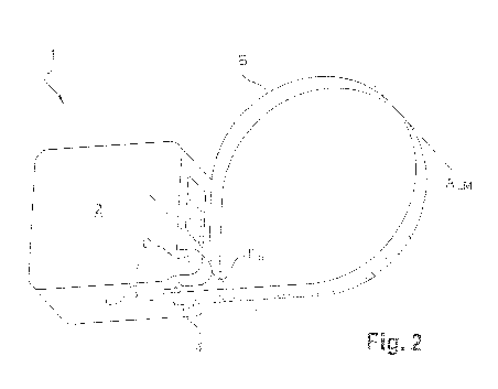
Figure 2 is a schematic representation corresponding to the first
embodiment of a measuring device 1 according to Figure 1, where the
measuring element 3 forms a loop B. As illustrated, when the distal end Ed
of the measuring element 3 is connected using the connecting means C, the
unwound portion Pd of the measuring element 3 forms a loop B that,
preferably, is placed in a single plane passing through a median longitudinal
axis ALm defined along the measuring element 3. This connection is
CA 03043505 2019-05-10
WO 2018/091462
PCT/EP2017/079198
14
achieved by interlocking a connecting element 5 present at the distal end Ed
of the measuring element 3 in the connecting means C.
Moreover, as also illustrated, the winder 2 has a reading window 6
for reading the circumference of the object/limb measured, where the
operator can determine the value (typically in centimetres and millimetres)
of the measured circumference.
Advantageously, a measuring device 1 as illustrated in Figure 1 and
in Figure 2 also comprises a locking system (not shown) and a rewinding
system, for example one that uses a motor or a spring (not shown), of the
measuring element 3. For example, these systems can be operated by a
button located on winder 2.
Figure 3 illustrates another measuring device 1 for measuring the
circumference of an object, in particular the circumference of a limb. This
measuring device 1 according to Figure 3 includes the same elements as
those shown in Figure 1, but the connecting means C and the exit opening
4 of the winder 2 are further apart from one another at a distance d of less
than or equal to 4 cm, preferably less than or equal to 3 cm, preferably less
than or equal to 2 cm, more preferably less than or equal to 1 cm.
Figure 4 illustrates yet another measuring device 1 for measuring of
the circumference of an object, in particular the circumference of a limb.
This
measuring device 1 according to Figure 3 comprises the same elements as
those shown in Figure 1, but the connecting means C is connected to a
mobile element Em designed to permit the movement of the connecting
means C (as indicated by the double arrow) at distance d defined between
the said exit opening 4 and the said connecting means C, i.e. at a distance
d of less than or equal to 4 cm, preferably less than or equal to 3 cm,
preferably less than or equal to 2 cm, more preferably less than or equal to
1 cm.
Figure 5 shows a measuring device 1 according to the invention,
connected to an iterative device for measuring the circumference of an
object/limb, such as the iterative measuring device according to document
W02014/191513.
CA 03043505 2019-05-10
WO 2018/091462
PCT/EP2017/079198
Example
In order to validate the measuring device according to the invention,
5 several measurements were made at different parts of the bodies of two
patients. As indicated in the table below, the following measuring devices
were compared:
- measuring device according to the invention where the distance d
defined between the exit opening and the said connecting means is
10 0.5 cm;
- measuring device of the prior art where the distance d defined
between the exit opening and the said connecting means is equal to
5.5 cm;
- a conventional measure (tape measure) as a reference (control).
15 Measurements
were taken at the index finger (above and to the
side), at the wrist when the device is positioned just behind the head of the
ulna (like a wristwatch), at the wrist when the device is offset by 90 with
respect to the position just behind the head of the ulna, at the ankle when
the device is positioned above the malleolus and at the ankle when the
device is offset by 90 with respect to the previous position.
The results obtained during these measurements are presented in
Table 1 below. In this Table, the measurements relating to the first
individual
are in "normal" font while the measurements of the second individual are
shown in italics.
Table 1
Wrist Finger (index) .. Ankle
Like a Offset by On top of Offset by Above the Offset by
wristwatch 900 the finger 900 malleolus
90
Tape 14.5 cm 14.5 cm 4.8 cm 4.8 cm 21.2
cm 21.3 cm
measure: 17.2 cm 17 cm 5.5 cm 5.5 cm 22.3 cm 22.3 cm
control
CA 03043505 2019-05-10
WO 2018/091462
PCT/EP2017/079198
16
Current 16.3 cm 17.2 cm 11 cm 11 cm 22.4 cm 21.3
cm
device 18 cm 19.4 cm 11 cm 11 cm 23.3 cm 22.2 cm
Device as 14.5 cm 14.5 cm 4.6 cm 4.6 cm 21.1 cm 21.1 cm
per the 17 cm 17 cm 5.5 cm 5.5 cm 22.1 cm 22.2 cm
invention
As can be seen, with a device according to the invention, for each
individual and each limb considered, only a difference of 1 to 2 mm is
observed compared to the measurements taken with the control (tape
measure). This proves that a device according to the invention enables
taking reliable measurements regardless of the positioning of the measuring
device on the limb in question.
On the contrary, with a device of the prior art (current device),
measurement differences of several centimetres (up to 6 cm in the case of
measuring the circumference of an index finger) are observed with respect
to the control. As can be seen, the smaller/thinner the limb, the more
erroneous and biased the measurement is when using a measuring device
according to the prior art, but not when using a device according to the
invention, which is versatile and allows taking measurements that are not
only reliable but also reproducible.
It is understood that this invention is in no way limited to the
embodiments described above and that many modifications may be made
without departing from the scope of the appended claims.