Note : Les descriptions sont présentées dans la langue officielle dans laquelle elles ont été soumises.
CA 03044090 2019-05-16
WO 2018/090143 PCT/CA2017/051375
METHODS AND APPARATUS FOR GENERATING GAS BUBBLES
Reference to Related Applications
[0001] This application claims priority from US application No. 62/424288
filed 18
November 2016. For the purposes of the United States of America, this
application claims
the benefit, under 35 USC 119, of US application No. 62/424288 filed 18
November 2016.
US application No. 62/424288 is hereby incorporated herein by reference.
Technical Field
[0002] Particular embodiments of this invention relate to methods and
apparatus for
generating gas bubbles and diffusing same in a liquid volume. Some embodiments
relate to
methods and apparatus for generating nano-sized gas bubbles, more
particularly, for
generating carbonic acid from mixing carbon dioxide with water. Particular
embodiments
relate to methods for local delivery of carbonic acid gas to patients (e.g. on
their epidermis)
for therapeutic applications.
Background
[0003] The therapeutic application of carbonic acid gas to humans is known.
Carbonic
acid gas is typically generated by mixing carbon dioxide with water in a
chamber and
passing the mixture through a porous membrane prior to discharge from the
chamber and
into a water volume. Carbonic acid then spreads throughout the water volume
(e.g. a tub or
the like), where a patient may be located. Typically, prior art carbonic acid
treatments
require water volume to have a pH level of between 4.2 and 5.2 for therapeutic
efficacy.
[0004] Conventional gas bubble generators are inefficient and expensive to
operate. In
particular, existing carbonic acid gas diffusers are slow to create carbonic
acid due to
inefficient mixing of CO2 into the water volume or otherwise and,
consequently, require
relatively large amounts of expensive carbon dioxide gas, particularly for
therapeutic
applications, where prior art diffusers are used to lower the pH level of an
entire volume of
water (e.g. a tub or the like) to the typical range of 4.2 to 5.2. There is
thus a general desire
for an improved apparatus and method for generating and disbursing carbonic
acid in
water. There is also a general desire for an efficient and cost-effective gas
bubble generator
that addresses or at least ameliorates some of the aforementioned drawbacks
with the prior
art gas bubble generators.
1
CA 03044090 2019-05-16
WO 2018/090143 PCT/CA2017/051375
[0005] The foregoing examples of the related art and limitations related
thereto are
intended to be illustrative and not exclusive. Other limitations of the
related art will become
apparent to those of skill in the art upon a reading of the specification and
a study of the
drawings.
Summary
[0006] The following embodiments and aspects thereof are described and
illustrated in
conjunction with systems, tools and methods which are meant to be exemplary
and
illustrative, not limiting in scope. In various embodiments, one or more of
the above-
described problems have been reduced or eliminated, while other embodiments
are
directed to other improvements.
[0007] One aspect of the invention provides an apparatus for generating gas
bubbles.
The bubble-generating apparatus comprises: a casing defining a casing bore
extending
longitudinally therethrough; and a diffuser located in the casing bore, the
diffuser defining a
diffuser bore extending longitudinally therethrough. The diffuser bore
comprises a fluid-input
region at or near a fluid-input end of the diffuser and a fluid-output region
at or near a fluid-
output end of the diffuser. A cross-sectional area of the diffuser bore in the
fluid-input region
is greater than the cross-sectional area of the diffuser bore in the fluid-
output region. At
least a portion of the diffuser is porous for permitting a flow of pressurized
gas from a region
of the casing bore located outside of the diffuser bore, through the porous
portion of the
diffuser and into the diffuser bore.
[0008] Another aspect of the invention provides a method for generating gas
bubbles in
a liquid. The method comprises: providing a bubble generator comprising: a
casing defining
a casing bore extending longitudinally therethrough; and a diffuser located in
the casing
bore, the diffuser defining a diffuser bore extending longitudinally
therethrough, the diffuser
bore comprising a fluid-input region at or near a fluid-input end of the
diffuser and a fluid-
output region at or near a fluid-output end of the diffuser, a cross-sectional
area of the
diffuser bore in the fluid-input region greater than the cross-sectional area
of the diffuser
bore in the fluid-output region. At least a portion of the diffuser is porous
for permitting a
flow of pressurized gas from a region of the casing bore located outside of
the diffuser bore,
through the porous portion of the diffuser and into the diffuser bore. The
casing comprises a
gas-input opening which provides fluid communication with a portion of the
casing bore
2
CA 03044090 2019-05-16
WO 2018/090143 PCT/CA2017/051375
located outside of the diffuser bore. The method also comprises: connecting
the fluid-input
region of the diffuser bore to receive a liquid at sufficient pressure to
create a pressure
gradient of the liquid in the diffuser bore to cause the received liquid to
flow longitudinally in
the diffuser bore toward the fluid-output region of the diffuser bore; and
connecting the gas-
input opening to receive gas at a pressure higher than the pressure of the
liquid in the
diffuser bore, such that the gas received at the gas-input opening moves from
the casing
bore, permeates the porous portion of the diffuser and enters the diffuser
bore to mix with
the liquid flowing longitudinally in the diffuser bore and the mixture of
liquid and gas bubbles
exits the fluid-output region of the diffuser bore.
[0009] Another aspect of the invention provides a method of delivering
localized
carbonic acid to a patient's skin. The method comprises: supplying carbon
dioxide and
water to a bubble generator to create a flow comprising a mixture of water and
carbon
dioxide gas in a form of bubbles comprising diameters in a range of about lOnm
to about
1000nm, the flow discharged from the bubble generator and into a tub of water;
and
locating a patient in the tub of water. Locating the patient in the tub of
water may comprise
causing physical interactions between the patient's skin and the carbon
dioxide bubbles and
thereby attracting the carbon dioxide bubbles to a region around the patient's
skin.
Attracting the carbon dioxide bubbles to the region around the patient's skin
may comprise
creating a corresponding localized region around the patient's skin of pH that
is lower than
a pH of a bulk of the water in the tub.
[0010] In addition to the exemplary aspects and embodiments described
above, further
aspects and embodiments will become apparent by reference to the drawings and
by study
of the following detailed descriptions.
Brief Description of the Drawings
[0011] Exemplary embodiments are illustrated in referenced figures of the
drawings. It
is intended that the embodiments and figures disclosed herein are to be
considered
illustrative rather than restrictive.
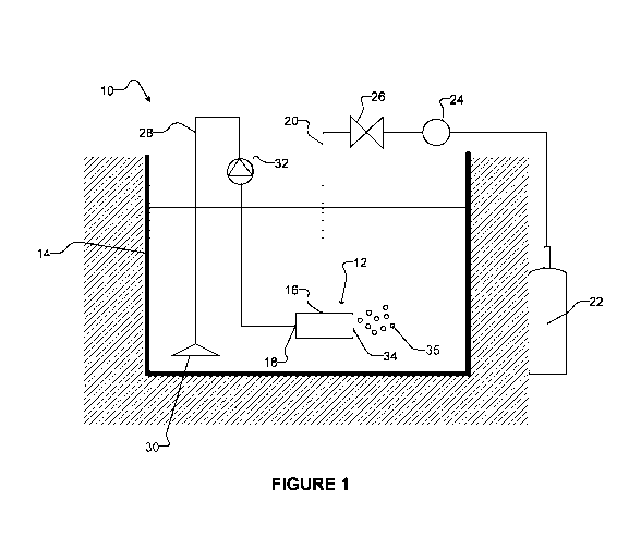
[0012] Figure 1 is a schematic view of a gas bubble delivery system
according to a
particular example embodiment.
3
CA 03044090 2019-05-16
WO 2018/090143 PCT/CA2017/051375
[0013] Figure 2 schematically illustrates the flow of liquid and gas into
and out of a gas
bubble generator according to a particular example embodiment.
[0014] Figure 3 is a partially exploded perspective view of a gas bubble
generator
shown with its casing removed according to a particular example embodiment.
[0015] Figure 4A is a perspective exploded view of the Figure 3 gas bubble
generator.
Figure 4B is a perspective exploded view of the Figure 3 gas bubble generator
with its
components shown as transparent.
[0016] Figure 5 is a partially exploded perspective view of the Figure 3
gas bubble
generator with its casing removed and with its components shown as
transparent.
[0017] Figure 6 is another partially exploded perspective view of the
Figure 3 gas
bubble generator with its casing removed and with its components shown as
transparent.
[0018] Figure 7A is a photograph of the skin of a patient suffering from
eczema before
gas bubble treatment. Figure 7B is a photograph of the skin of the same
patient suffering
from eczema after gas bubble treatment taken five days later after two twenty
minute
sessions per day in the Figure 1 gas bubble delivery system.
Description
[0019] Throughout the following description specific details are set forth
in order to
provide a more thorough understanding to persons skilled in the art. However,
well known
elements may not have been shown or described in detail to avoid unnecessarily
obscuring
the disclosure. Accordingly, the description and drawings are to be regarded
in an
illustrative, rather than a restrictive, sense.
[0020] One aspect of the invention provides an apparatus for generating gas
bubbles.
The bubble-generating apparatus comprises: a casing defining a casing bore
extending
longitudinally therethrough; and a diffuser located in the casing bore, the
diffuser defining a
diffuser bore extending longitudinally therethrough. The diffuser bore
comprises a fluid-input
region at or near a fluid-input end of the diffuser and a fluid-output region
at or near a fluid-
output end of the diffuser. A cross-sectional area of the diffuser bore in the
fluid-input region
is greater than the cross-sectional area of the diffuser bore in the fluid-
output region. At
4
CA 03044090 2019-05-16
WO 2018/090143 PCT/CA2017/051375
least a portion of the diffuser is porous for permitting a flow of pressurized
gas from a region
of the casing bore located outside of the diffuser bore, through the porous
portion of the
diffuser and into the diffuser bore.
[0021] Another aspect of the invention provides a method for generating gas
bubbles in
a liquid. The method comprises: providing a bubble generator comprising: a
casing defining
a casing bore extending longitudinally therethrough; and a diffuser located in
the casing
bore, the diffuser defining a diffuser bore extending longitudinally
therethrough, the diffuser
bore comprising a fluid-input region at or near a fluid-input end of the
diffuser and a fluid-
output region at or near a fluid-output end of the diffuser, a cross-sectional
area of the
diffuser bore in the fluid-input region greater than the cross-sectional area
of the diffuser
bore in the fluid-output region. At least a portion of the diffuser is porous
for permitting a
flow of pressurized gas from a region of the casing bore located outside of
the diffuser bore,
through the porous portion of the diffuser and into the diffuser bore. The
casing comprises a
gas-input opening which provides fluid communication with a portion of the
casing bore
located outside of the diffuser bore. The method also comprises: connecting
the fluid-input
region of the diffuser bore to receive a liquid at sufficient pressure to
create a pressure
gradient of the liquid in the diffuser bore to cause the received liquid to
flow longitudinally in
the diffuser bore toward the fluid-output region of the diffuser bore; and
connecting the gas-
input opening to receive gas at a pressure higher than the pressure of the
liquid in the
diffuser bore, such that the gas received at the gas-input opening moves from
the casing
bore, permeates the porous portion of the diffuser and enters the diffuser
bore to mix with
the liquid flowing longitudinally in the diffuser bore and the mixture of
liquid and gas bubbles
exits the fluid-output region of the diffuser bore.
[0022] Another aspect of the invention provides a method of delivering
localized
carbonic acid to a patient's skin. The method comprises: supplying carbon
dioxide and
water to a bubble generator to create a flow comprising a mixture of water and
carbon
dioxide gas in a form of bubbles comprising diameters in a range of about lOnm
to about
1000nm, the flow discharged from the bubble generator and into a tub of water;
and
locating a patient in the tub of water. Locating the patient in the tub of
water may comprise
causing physical interactions between the patient's skin and the carbon
dioxide bubbles and
thereby attracting the carbon dioxide bubbles to a region around the patient's
skin.
CA 03044090 2019-05-16
WO 2018/090143 PCT/CA2017/051375
Attracting the carbon dioxide bubbles to the region around the patient's skin
may comprise
creating a corresponding localized region around the patient's skin of pH that
is lower than
a pH of a bulk of the water in the tub.
[0023] Figure 1 is a schematic view of a gas bubble delivery system 10
according to a
particular example embodiment. Gas bubble delivery system 10 comprises a gas
bubble
generator 12 placed inside a tank 14 filled (at least in part) with liquid
(e.g. water). Tank 14
may be a bath tub, a hot tub and/or the like. Gas bubble generator 12 may be
submerged in
the liquid in tank 14. Gas bubble generator 12 comprises a gas-input opening
16 and a
liquid-input opening 18 for receiving a flow of gas and liquid, respectively,
into a body of
generator 12. A mixture of gas and liquid, in the form of a plurality of gas
bubbles 35, exit
generator 12 from a fluid-output opening 34. When the plurality of gas bubbles
35 discharge
from generator 12, they may spread and diffuse in the liquid volume inside
tank 14.
[0024] In some embodiments, a gas supply line 20 connects a gas source 22
to gas-
input opening 16 of the generator 12. Gas source 22 may be remote from tank
14. Gas
source 22 may be pressurized or gas provided to gas-input opening 16 may be
otherwise
pressurized, so that gas is driven into bubble generator 12 by a pressure
gradient. In some
embodiments, gas source 22 comprises a gas cylinder, in which gas is stored
under
pressure. Alternatively, a compressor (not shown) may be operatively connected
to gas
source 22 and/or to supply line 20 to pressurize the gas for delivery into
generator 12 via
gas-input opening 16. A skilled person will appreciate that conventional fluid
control
components, such as, by way of non-limiting example pressure regulators 24 and
control
valves 26, may be connected to the gas supply line 20 for controlling various
parameters
(e.g. volume, flow rate, pressure and/or the like) of pressurized gas that
flows into bubble
generator 12 via gas-input opening 16. In some embodiments, the gas is carbon
dioxide. In
some embodiments, the pressurized gas that is delivered into generator 12 is
under a
pressure of approximately 500 to 4000 psi. In other embodiments, this pressure
range is
1000 to 200 psi.
[0025] In some embodiments, a feed line 28 connects a liquid-source opening
30 to
liquid-input opening 18 of bubble generator 12. Liquid pump 32 (and/or other
fluid control
components) may be operatively connected between liquid-source opening 30 and
liquid-
input opening 18 for supplying and controlling various parameters (e.g.
volume, flow rate,
6
CA 03044090 2019-05-16
WO 2018/090143
PCT/CA2017/051375
pressure and/or the like) of liquid supplied to bubble generator 12. The
pressure at which
liquid is supplied to liquid-input opening 18 may be less than the pressure at
which gas is
supplied to gas-input opening 16. In some embodiments, pump 32 is not required
because
the supply of gas at gas-input opening 16 and/or the location of liquid-source
opening 30
relative to liquid-input opening 18 (e.g. placing liquid-source opening 30
above liquid-input
opening) can create pressure gradient that draws liquid through liquid-input
opening 18. In
some embodiments, the liquid supplied to generator 12 is water. In the
illustrated
embodiment, liquid-source opening 30 is located in the liquid contained in
tank 14 to
provide liquid from tank 14 to bubble generator 12. In some embodiments,
liquid-source
opening 30 can be located external to tank 14 (e.g. in a filtration system or
the like (not
shown) which removes liquid from tank 14 for filtration purposes). In some
embodiments,
liquid-source opening 30 may be connected to receive liquid from an external
liquid source
¨ i.e. a liquid source other than the liquid in tank 14. In some such
embodiments, the rate of
which water flows through feed line 28 into bubble generator 12 is in a range
of about 1 to
gallons per minute, and the rate of which gas flows through gas supply line 20
into
generator 12 is in a range of about 25 to 150 cc per minute at a pressure of
approximately 1
to 100 psi, although operation outside of these ranges is possible.
[0026] Figure 2 schematically illustrates a bubble generator 12 and the
flow of gas and
liquid into and out of gas bubble generator 12 according to a particular
embodiment. Bubble
generator 12 of the Figure 2 embodiment comprises a casing 11 which defines a
casing
bore 13 that extends in a longitudinal liquid-flow direction (shown by arrow
15) through
casing 11. Bubble generator 12 also comprises a diffuser 17 located in casing
bore 13.
Diffuser 17 defines a diffuser bore 19 which extends in longitudinal direction
15 through
diffuser 17. Diffuser bore 19 comprises a fluid-input region 19A and a fluid-
output region
19B, where a cross-sectional area of the diffuser bore 19 (in a cross-section
perpendicular
to longitudinal liquid-flow direction 15) is greater at the fluid-input region
19A than at the
fluid-output region 19B. At least a portion 23 of diffuser 17 is porous.
Liquid enters bubble
generator 12 from liquid-input opening 18, and gas enters bubble generator 12
from gas-
input opening 16. In particular, liquid flows into fluid-input region 19A of
diffuser bore 19 at
or near liquid-input opening 18. Gas, which may be introduced to bubble
generator 12
under pressure that is greater than the pressure of liquid in diffuser bore
19, flows into
casing bore 13 through gas-input opening 16 and then, from a region 21 of the
casing bore
7
CA 03044090 2019-05-16
WO 2018/090143 PCT/CA2017/051375
13 located outside of diffuser 17 and its bore 19, through the porous portion
23 of diffuser
17 and into diffuser bore 19. Gas introduced into diffuser bore 19 thorough
porous diffuser
portion 23 mixes with the liquid inside bubble generator 12 and, in
particular, with the liquid
introduced into diffuser bore 19 from liquid-input opening 18. As a result, a
gas and liquid
mixture flows out of diffuser bore 19 and out of generator 12 from fluid-
output opening 34.
The output gas and liquid mixture comprises gas bubbles 35 (Figure 1).
[0027] In some embodiments, the input liquid is water, and the input gas is
carbon
dioxide. In such embodiments, the gas and liquid mixture that exits bubble
generator 12
may comprise carbonic acid or may generate carbonic acid. It is expected that
at the
exemplary ranges of input water and gas flow rates suggested herein, the
change in pH of
the bulk liquid held in tank 14 after the addition of gas bubbles will be less
than about 0.1
(e.g. a pH of 6.9-7 in the case of water). In some embodiments, marginal
decrease in pH of
the bulk liquid held in tank 14 may be detected and/or monitored. In
particular
embodiments, the bulk liquid held in tank 14 after the addition of gas bubbles
has a pH in
the range of about 6 to less than 7. In some embodiments, the bulk liquid held
in tank 14
after the addition of gas bubbles has a pH in the range of about 5.2 to 7.5.
[0028] Figures 3 to 6 show a bubble generator 112 according to another
particular
embodiment. Bubble generator 112 shares many features in common with bubble
generator
12 shown in Figure 2 and similar reference numerals (differing by 100) are
used to describe
common features as between the two bubble generators 12, 112. Gas bubble
generator
112 of the illustrated embodiment comprises a casing assembly 111 which itself
comprises
an elongated (in longitudinal fluid-flow direction 15) and generally
cylindrical casing body
36, an input cap 44 and an output cap 48. Bubble generator 112 and the
components of
casing assembly 111 of the illustrated embodiment have generally annular cross-
sections
(perpendicular to longitudinal direction 15) to define a circular cross-
section casing bore 113
that extends in longitudinal direction 15 through casing assembly 111. These
shapes of the
components of casing assembly 111 and casing bore 113 are not necessary. In
some
embodiments, bubble generator 12, the components of casing assembly 111 and/or
casing
bore 113 may have other cross-sectional shapes.
[0029] Input cap 44 and output cap 48 are connectable to casing body 36 at
respective
longitudinally opposing ends of casing body 36. In the illustrated embodiment,
input cap 44
8
CA 03044090 2019-05-16
WO 2018/090143 PCT/CA2017/051375
comprises a coupling surface 44A that is complementary to a portion of casing-
bore
defining surface 113A of casing body 36 and surfaces 44A and 113A can connect
together
via friction fit, by using suitable adhesive, suitable fasteners, combinations
thereof and/or
the like. In the particular case of the illustrated embodiment, coupling
surface 44A of input
cap may be inserted into casing bore 113 to abut against casing-bore defining
surface 113A
and a suitable adhesive may be used to complete the connection of these two
surfaces. In
the illustrated embodiment, input cap 44 also comprises a second coupling
surface 44B that
abuts against an input end of casing body 36 and a suitable adhesive may be
used to
complete the connection of these two surfaces. In the illustrated embodiment,
output cap 48
comprises similar coupling surfaces 48A, 48B that may be similarly connected
to casing
body 36 at the opposing longitudinal end. In some embodiments, input cap 44
and output
cap 48 may be connected to casing body 36 using other suitable techniques. The
connections of input cap 44 and output cap 48 to casing body 36 may be
impermeable to
gas at the pressures of gas used in casing bore 113.
[0030] In some embodiments, casing assembly 111 (when assembled) comprises
a
length in a range of approximately 1/4 to 6 inches. In some embodiments,
casing assembly
111 (when assembled) comprises a length in a range of approximately 1 to 2
inches. The
inventor considers that these ranges are flexible depending on the
applications in which
diffuser 112 is used. Lengths of up to several feet may be used in some
applications. In
some embodiments, casing bore 113 may have a cross-sectional area
(perpendicular to
longitudinal direction 15) in a range of approximately 0.25-30 square inches.
In some
embodiments, this size may be in a range of 0.5-4 square inches. Other
suitable
dimensions may be possible for other applications.
[0031] Casing body 36 of the illustrated embodiment defines a gas-input
opening 116
which provides fluid communication between an outside of casing assembly 111
and casing
bore 113. Gas-input opening 116 may comprise an aperture defined on a face 37
of casing
body 36 which leads to casing bore 113. In some embodiments, the aperture of
gas input
opening 116 may have a cross-sectional area in a range of approximately 0.01
to 2.5
square inches, although other sizes of gas-input opening 116 may be used for
other
applications. In the illustrated embodiments, gas-input opening 116 is
positioned at
approximately halfway along the longitudinal dimension of casing body 36.
9
CA 03044090 2019-05-16
WO 2018/090143 PCT/CA2017/051375
[0032] Bubble generator 112 also comprises a diffuser 117 which, when
bubble
generator is assembled, is located in casing bore 113 between input cap 44 and
output cap
48. Diffuser 117 is shaped to define a diffuser bore 119 which extends in
longitudinal
direction 15 through diffuser 117. At least a portion 123 of diffuser 117 is
porous to permit
gas flow from an exterior of diffuser 117 through porous portion 123 and into
diffuser bore
119 to create bubbles (e.g. nano-bubbles), as explained in more detail below.
In some
embodiments, porous portion 123 comprises pores having cross-sectional
dimensions of
less than 7511m across. In some embodiments, porous portion 123 comprises
pores having
cross-sectional dimensions of less than 5011m across. In some embodiments,
porous
portion 123 comprises pores having cross-sectional dimensions of less than
2511m across.
In the illustrated embodiment, porous portion 123 makes up all or
substantially all of diffuser
117. Diffuser 117 is shaped such that diffuser bore 119 comprises a fluid-
input region 119A
(relatively close to input cap 44) and a fluid-output region 119B (relatively
close to output
cap 48) where fluid-input region 119A has a cross-sectional area (in a
direction
perpendicular to longitudinal direction 15) that is greater than the cross-
sectional area of
fluid-output region 119B (see Figure 4B). In the particular case of the
illustrated
embodiment, diffuser bore 119 has a frustro-conical shape having a wide end at
fluid-input
region 119A and a narrow end at fluid-output region 119B and a smoothly
angularly
decreasing cross-sectional area with movement along longitudinal direction 15.
As best
shown in Figures 5 and 6, diffuser bore 119 of the illustrated embodiment
tapers along the
length of diffuser 117 from fluid-input region 119A to fluid-output region
119B at a constant
diffuser bore angle. In some embodiments, the diffuser bore angle is in a
range of
approximately 0.5 to 45 . In some embodiments, the diffuser bore angle is in
a range of
approximately 2 to 20 . In some embodiments, the bore angle is in a range of
approximately 3 to 10 .
[0033] When bubble generator 112 is assembled, an input end 117A of
diffuser 117
may engage or be connected to input cap 44 and an output end 117B of diffuser
117 may
engage or be connected to output cap 48. In the illustrated embodiment, input
cap 44
comprises a channel 44C which is complementary in shape to a rim 117C on input
end
117A of diffuser 117. Channel 44C opens in longitudinal direction for
receiving rim 117C on
input end 117A of diffuser 117 (see Figures 4B and 5). In some embodiments,
input end
117A of diffuser 117 may be friction fit into channel 44C, adhesively
connected to the
CA 03044090 2019-05-16
WO 2018/090143 PCT/CA2017/051375
surfaces in channel 44C, combinations thereof and/or the like, although this
is not
necessary. Output cap 48 may comprise a similar channel 48C (Figure 4B) for
engaging or
connecting to output end 117B (e.g. to a rim 117D on output end 117B) of
diffuser 117.
[0034] Input cap 44 is shaped to define a liquid-input opening 118 which,
when bubble
generator 112 is assembled, provides fluid communication between an exterior
of casing
assembly 111 to diffuser bore 119. Liquid-input opening 118 may have a cross-
sectional
area (perpendicular to longitudinal direction 15) that is the same size or
larger than the
cross-sectional area of diffuser bore 119 in fluid-input region 119A, although
this is not
necessary. Similarly, output cap 48 is shaped to define a fluid-output opening
134 which,
when bubble generator 112 is assembled, provides fluid communication between
diffuser
bore 119 and an exterior of casing assembly 111. In the illustrated
embodiment, fluid-output
opening 134 has a cross-sectional area (perpendicular to longitudinal
direction 15) that is
the same size or smaller than the cross-sectional area of diffuser bore 119 in
fluid-output
region 119B, although this is not necessary.
[0035] Bubble generator 112 operates as follows. Liquid is provided to
liquid-input
opening 118 and pressurized gas is provided to gas-input opening 116, as
discussed above
in connection with bubble generator 12 of Figure 2. Liquid (e.g. water) may be
forced
through liquid-input opening 118 by any suitable means of creating a pressure
differential
and enters diffuser bore 119 at or near fluid-input region 119A. Gas (e.g.
carbon dioxide)
may be forced through gas-input opening 116 by any suitable means of creating
a pressure
differential and enters the region 121 (Figure 2) of casing bore 113 that is
external to
diffuser 117 and its diffuser bore 119. The gas, which may be introduced to
bubble
generator 112 at a higher pressure than the liquid introduced into diffuser
bore 119, is
forced from region 121 through the porous portion 123 of diffuser 117 and into
diffuser bore
119, where the gas forms bubbles (e.g. nano-bubbles) in the liquid flowing
through diffuser
bore 119. The fluid mixture of liquid and gas bubbles (e.g. nano-bubbles)
exits from diffuser
bore 119 and from bubble generator 112 via fluid-output opening 134.
[0036] Without wishing to be bound to any theory, the inventors believe
that providing
diffuser bore 119 with a relatively larger cross-sectional area in fluid-input
region 119A and
a relatively smaller cross-sectional area in fluid-output region 119B, and/or
the tapered
shape of diffuser bore 119 between fluid-input region 119A and fluid-output
region 119B,
11
CA 03044090 2019-05-16
WO 2018/090143 PCT/CA2017/051375
allows for increased efficiency in generating and disbursing of gas bubbles
into a liquid
volume. The relatively larger cross-sectional area of diffuser bore 119 at the
fluid-input
region 119A creates a large surface area of diffuser 117 for input gas to flow
into diffuser
bore 119. Consequently, a large volume of gas can be forced from region 121 of
casing
bore 113, through porous portion 123 of diffuser 117, and into diffuser bore
119. The
relatively large surface area of diffuser 117 in fluid-input region 119A also
creates lower
fluid pressure inside diffuser 117, thereby reducing back pressure which would
hinder the
flow of fluid. The tapering of diffuser bore 119 (and/or the relative sizes of
diffuser bore 119
in fluid-input region 119A and fluid-output region 119B) also increases fluid
velocity as fluid
travels in longitudinal direction 15 through diffuser bore 119 from fluid-
input region 119A
through to fluid-output region 119B , thereby increasing the amount of gas
bubbles that may
be introduced into the liquid traveling through diffuser bore 119 and diffused
into the
surrounding pool of liquid at a given time. The tapering of the diffuser bore
119 (and/or the
relative sizes of diffuser bore 119 in fluid-input region 119A and fluid-
output region 119B)
relative to a constant bore size also reduces the resident time of bubbles on
the bore-
defining surface of diffuser 117 and thereby, maintains the size of bubbles at
an acceptably
small level. For example, bubbles with long residency time in diffuser 117 may
become
undesirably large.
[0037] In some embodiments, casing assembly 111 (including casing body 36,
input
cap 44 and/or output cap 48) are made of plastic, but could generally be made
of other
suitable materials that are capable retaining liquid. Diffuser 117 and/or the
porous portion
123 of diffuser 117 may be made of any suitable porous material, including,
but not limited
to ceramic, metal, rayon, wood, bamboo, porous plastic, carbon material,
graphite material,
carbon-graphite composite material and/or other suitable materials. In some
embodiments,
porous portion 123 comprises pores having cross-sectional dimensions of less
than 7511m
across. In some embodiments, porous portion 123 comprises pores having cross-
sectional
dimensions of less than 5011m across. In some embodiments, porous portion 123
comprises
pores having cross-sectional dimensions of less than 2511m across.
[0038] Individual gas bubbles that are generated and diffused by various
bubble-
generator embodiments may comprise diameters in the nanometer or micrometer
ranges.
In particular embodiments, the size of individual gas bubbles may be in a
range of about 10
12
CA 03044090 2019-05-16
WO 2018/090143 PCT/CA2017/051375
¨ 1000nm in diameter. In some embodiments, the size of individual gas bubbles
may be in
a range of about 10 ¨ 300nm in diameter. In some embodiments, the size of
individual gas
bubbles may be in a range of about 10 ¨ 100nm in diameter. One skilled in the
art will
appreciate that the size of the generated gas bubbles varies depending on the
velocity of
the liquid input into bubble generator 12, 112 and the pressure of the input
gas that flow into
bubble generator 12, 112 and on the characteristics of diffuser 17, 117, such
as the pore
size of the porous portion 23, 123 of diffuser 17, 117.
[0039] Another aspect of the invention relates to methods for delivery of
carbonic acid
via carbon dioxide gas bubbles to patients (e.g. humans or other animals) for
therapeutic
applications. Some embodiments provide methods for therapeutic delivery of
carbonic acid
via carbon dioxide gas bubbles having a diameter within the nanometer range to
patients
located inside a water volume. Particular embodiments relate to methods for
therapeutic
delivery (to humans or other animals) of carbonic acid via carbon dioxide gas
bubbles using
gas bubble generator 12 as discussed above.
[0040] In some embodiments, carbon dioxide gas bubbles are discharged from
a gas
bubble generator and then freely disperse in a water volume such as a bath
tub, a hot tub
and/or the like (e.g. the water in tank 14 (Figure 1)), where they form
carbonic acid in the
water. The size of individual gas bubbles may be in a range of approximately
10 to 1000nm
in diameter. In some embodiments, the size of individual gas bubbles may be in
a range of
about 10 ¨ 300nm in diameter. In some embodiments, the size of individual gas
bubbles
may be in a range of about 10 ¨ 100nm in diameter. The size of the gas bubbles
that are
generated from the gas bubble generator is dependent upon the pore size of the
membrane
that is used for the diffuser of the generator.
[0041] Without bound to any theory, individual gas bubbles having diameters
within the
nanometer ranges discussed herein carry their own charges ¨ e.g. negative
charges. This
charge of the carbon dioxide gas bubbles may interact electrostatically or
otherwise (e.g. by
van der Waals forces or the like) with the electrically charged skin of the
patient, which is s
typically hydrophilic and which typically has charged particles on its surface
or otherwise
exhibits surface charge. Consequently, the charged (e.g. negatively charged)
gas bubbles
adhere to, or are attracted to, the surfaces of the patient's skin and form a
thin layer of
carbon dioxide gas and/or a corresponding thin layer of carbonic acid on,
and/or in a vicinity
13
CA 03044090 2019-05-16
WO 2018/090143
PCT/CA2017/051375
of, the skin. Without wishing to be bound by theory, the inventors consider
that adherence
of, or proximity of, the carbon dioxide gas bubbles to the patient's skin
creates a localized
carbonic acid zone of correspondingly low pH in a vicinity of the skin of the
patient, thereby
creating therapeutic pH levels at or around the patient without using as much
carbon
dioxide gas as prior art techniques, which involve large sized gas bubbles and
lowering the
pH of the entire volume of water in tub 14 (e.g. by introducing enough carbon
dioxide to
lower the pH of the entire volume of tub 14). Further, adherence of or
proximity of the
carbon dioxide gas bubbles to the human skin minimizes the spread of gas
bubbles to other
regions of the water volume. This is desirable since the spread of gas bubbles
to regions
away from the human body results in gas bubbles not being therapeutically
exploited and
thus wasted.
[0042] Typical
therapeutic applications of carbonic acid involve exposing the patient's
skin to acidic environments with a pH less than 7.0 and, in most cases, a pH
below 5.2 and,
in some cases, as low as 4.2 or lower. In accordance with some aspects of the
invention,
such a therapeutically useful acidic pH (i.e., pH less than 7.0, more
preferably at around pH
4.2-5.2) would be created in a localized region of the water volume where the
patient's body
is located. For example, in some embodiments, this localized region is within
2.5cm of the
skin of the patient. In some this localized region is within 1cm of the skin
of the patient. In
some this localized region is within 0.5cm of the skin of the patient. The pH
of the bulk of
the remaining water volume in tank 14 (i.e. in the water spaced apart from the
patient)
would be much higher than 5.2. For example, in some embodiments, this bulk
water region
is spaced apart from the skin of the patient by more than 5 cm. In some
embodiments, this
bulk water region is spaced apart from the skin of the patient by more than 10
cm. In some
embodiments, this bulk water region is spaced apart from the skin of the
patient by more
than 20 cm. In some cases, the pH of the bulk of the water in tank 14 (and
spaced apart
from the patient) may be greater than 5.5 while a patient is being treated
with carbon
dioxide bubbles in a localized region of low pH in an immediate vicinity the
patient. In some
cases, the pH of the bulk of the water in tank 14 (and spaced apart from the
patient) may be
greater than 6.5 while a patient is being treated with carbon dioxide bubbles
in a localized
region of low pH. In some cases, the pH of the bulk of the water in tank 14
(and spaced
apart from the patient) may be greater than 6.8 while a patient is being
treated with carbon
dioxide bubbles in a localized region of low pH in an immediate vicinity of
the patient. The
14
CA 03044090 2019-05-16
WO 2018/090143 PCT/CA2017/051375
delivery of localized acidic pH in a range of about pH 4.2-5.2 around a
patient by the use of
nano-sized carbon dioxide gas bubbles has at least the advantage of using low
levels of
input carbon dioxide (such as a carbon dioxide flow rate into the diffuser in
a range of about
50 to 1000 cc/min) to achieve the therapeutic benefits to humans or animals.
This is
considered to be very low levels of input carbon dioxide as compared to prior
art techniques
involving larger volumes of carbon dioxide gas to lower the pH of the entire
water volume in
the tank. In particular, the inventors believe that its method could involve
using only about
1% of the total carbon dioxide gas required by certain prior art techniques to
achieve
equivalent therapeutic benefits to humans or animals.
Experimental Example 1
[0043] An experimental apparatus for gas bubble generator 12, 112 was
tested on a
patient who appears to suffer from eczema. Eczema, also known as atopic
dermatitis, is a
form a skin disease that causes the skin to become inflamed or irritated.
Figure 7A shows
the eczema rash on the patient's elbow before gas bubble treatment.
[0044] A gas bubble generator 12, 112 was placed inside a bath tub 14. The
taper
angle of the diffuser bore 19, 119 between fluid-input region 19A, 119A and
fluid-output
region 19B, 119B was approximately 7.50. The bath tub was filled with water
after a
sufficient amount of carbon dioxide gas has flown through diffuser 17, 117 so
that generator
12, 112 was not saturated with water. Water and pressurized carbon dioxide gas
were
supplied into generator 12, 112 through their respective openings (see
discussion above). A
carbon dioxide flow control valve was operatively connected to control the
flow of
pressurized carbon dioxide gas into generator 12, 112. The pressurized gas
that was
delivered into generator 12, 112 created a pressure differential between the
gas inside and
the water outside of generator 12, 112 of about 29 psi. The rate at which the
gas was
supplied into generator 12,112 was maintained at approximately 75 cc/min. The
gas
bubbles discharged by generator 12, 112 were spread and diffused in the water
volume
where the patient's elbow was located. The temperature of the water volume was
in the
range of between 95 to 106 F. The water volume comprising the gas bubbles
discharged by
generator 12 under these conditions was reported, by the patient, to create a
silky texture.
Without bound to any theory, it is believed by the inventors that the silky
texture in the water
volume comprising gas bubbles helps to determine the efficacy of the gas
bubble generator
CA 03044090 2019-05-16
WO 2018/090143 PCT/CA2017/051375
12, 112 in the treatment of skin diseases.
[0045] Figure 7B is a photograph of the skin of the same (Figure 7A)
patient suffering
from eczema after gas bubble treatment taken six days later after two twenty
minute
sessions per day using the experimental bubble generating system under the
specified
conditions.
Interpretation of Terms
[0046] Unless the context clearly requires otherwise, throughout the
description and the
claims:
= "comprise", "comprising", and the like are to be construed in an
inclusive sense, as
opposed to an exclusive or exhaustive sense; that is to say, in the sense of
"including, but not limited to";
= "connected", "coupled", or any variant thereof, means any connection or
coupling,
either direct or indirect, between two or more elements; the coupling or
connection
between the elements can be physical, logical, or a combination thereof;
elements
which are integrally formed may be considered to be connected or coupled;
= "herein", "above", "below", and words of similar import, when used to
describe this
specification, shall refer to this specification as a whole, and not to any
particular
portions of this specification;
= "or", in reference to a list of two or more items, covers all of the
following
interpretations of the word: any of the items in the list, all of the items in
the list, and
any combination of the items in the list;
= the singular forms "a", "an", and "the" also include the meaning of any
appropriate
plural forms.
[0047] Words that indicate directions such as "vertical", "transverse",
"horizontal",
"upward", "downward", "forward", "backward", "inward", "outward", "vertical",
"transverse",
"left", "right", "front", "back", "top", "bottom", "below", "above", "under",
and the like, used in
this description and any accompanying claims (where present), depend on the
specific
orientation of the apparatus described and illustrated. The subject matter
described herein
16
CA 03044090 2019-05-16
WO 2018/090143 PCT/CA2017/051375
may assume various alternative orientations. Accordingly, these directional
terms are not
strictly defined and should not be interpreted narrowly.
[0048] Specific examples of systems, methods and apparatus have been
described
herein for purposes of illustration. These are only examples. The technology
provided
herein can be applied to systems other than the example systems described
above. Many
alterations, modifications, additions, omissions, and permutations are
possible within the
practice of this invention. This invention includes variations on described
embodiments that
would be apparent to the skilled addressee, including variations obtained by:
replacing
features, elements and/or acts with equivalent features, elements and/or acts;
mixing and
matching of features, elements and/or acts from different embodiments;
combining features,
elements and/or acts from embodiments as described herein with features,
elements and/or
acts of other technology; and/or omitting combining features, elements and/or
acts from
described embodiments.
[0049] It is therefore intended that the following appended claims and
claims hereafter
introduced are interpreted to include all such modifications, permutations,
additions,
omissions, and sub-combinations as may reasonably be inferred. The scope of
the claims
should not be limited by the preferred embodiments set forth in the examples,
but should be
given the broadest interpretation consistent with the description as a whole.
[0050] While a number of exemplary aspects and embodiments are discussed
herein,
those of skill in the art will recognize certain modifications, permutations,
additions and sub-
combinations thereof. For example:
= In some embodiments, one or both of input cap 44 or output cap 48 may be
integrally formed with casing b0dy36.
= In some embodiments, gas-input opening 116 may be provided on one or both
of
input cap 44 and output cap 48 in addition to or in the alternative to being
provided
on casing body 36.
17