Note : Les descriptions sont présentées dans la langue officielle dans laquelle elles ont été soumises.
Short-circuit braking of an LLM
The subject of the invention relates to a method for driving a plurality of
drive coils of a long-
stator linear motor, wherein in normal operation the drive coils are energized
such that a
magnetic field coupled to a transport unit is moved along a direction of
motion to move the
transport unit along the direction of motion. The subject of the invention
also relates to a
long-stator linear motor having a plurality of drive coils and at least one
transport unit, where-
in the drive coils are energized by an LLM control system which is controlled
by a coil con-
troller such that a magnetic field coupled to the transport unit is moved
along a direction of
motion in order to move the transport unit along the direction of motion.
In order to meet the requirements of modern, flexible logistics units, long-
stator linear motors
(LLMs) are increasingly being used as a replacement for conventional
continuous conveyors,
for example rotary-to-linear conversion units such as rotary motors on a
conveyor belt. Long-
stator linear motors are characterized by a better and more flexible
utilization over the entire
working range. Thus the ranges of the speed and acceleration can be exploited
from zero to
the maximum. Other advantages which must be mentioned include individual
regulation or
control of the movable transport units (shuttles), improved energy
utilization, reduction of
maintenance costs due to the lower number of wear parts, ease of replacement
of transport
units, efficient monitoring and easier fault detection, and optimization of
the current con-
sumed resulting from the elimination of current gaps.
A stator of a long-stator linear motor consists of a plurality of drive coils
disposed next to one
another in the direction of motion of the transport units, the coils together
forming the stator
of the long-stator linear motor. These drive coils are controlled individually
or in groups, and it
is often desirable or necessary in the operation of the long-stator linear
motor to change the
polarity, i.e. the current direction of the drive coils. By controlling the
drive coils, a moving
magnetic field is generated which cooperates with excitation magnets (usually
permanent
magnets) on a transport unit of the LLM in order to generate a drive force
acting on the
transport unit and thus move the transport unit along the stator. To energize
the drive coils
for generating the magnetic field, an operating voltage is usually provided
between a first
operating potential and a second operating potential. Such long-stator linear
motors are well
known in various embodiments, for example from WO 2013/143783 Al, US Pat. No.
6,876,107 B2, US 2013/0074724 Al or WO 2004/103792 Al, to name only a few.
One possibility for energizing drive coils and allowing a change in the
polarity of the coil volt-
age would be the use of a full bridge, as disclosed in US 2006/0220623 Al. The
operating
voltage is applied to the first and to the second branch of the full bridge,
the drive coil being
placed in the shunt branch of the full bridge. By suitable control of the four
switches (bipolar
transistors, MOSFETs, IGBTs, etc.) of the full bridge, a target coil voltage,
i.e. a voltage pre-
-1-
CA 3045839 2019-06-11
determined by a coil controller system, can be applied to the drive coils at
the desired polarity
and magnitude. To be able to control the drive coils individually, each drive
coil must be pro-
vided with a full bridge. However, this means that four switches are required
per drive coil. Of
course, when there is a high number of drive coils for an LLM stator, high
costs and a high
circuit complexity result due to the large number of switches.
AT 518 721 Al discloses the use of half bridges instead of full bridges,
wherein a midpoint of
the half bridges is connected to a first terminal of drive coils,
respectively. The second termi-
nals of the drive coils are connected to a control point and a control unit
regulates an actual
potential at the control point to a predetermined potential. Thus, despite the
use of half bridg-
es, a positive and a negative coil voltage can be applied to the drive coils.
It may be desirable to quickly decelerate a transport unit. In some
exceptions, such as when
the safety of persons in the vicinity of the long-stator linear motor is at
risk, overloading of the
system, voltage overloads and loss of position or speed information, for
example, it may be
necessary to initiate an immediate emergency stop, whereby all or part of the
transport units
(e.g. all transport units of a certain sector) must be brought to a
standstill. For example, US
2012/193172 discloses special brake coils mounted on a linear motor for
generating a brak-
ing effect. However, such additional brake coils increase the design
complexity and the cost
of the long-stator linear motor and are therefore undesirable.
It is an object of the present invention to easily enable a safe deceleration
of a transport unit
of a long-stator linear motor.
This object is achieved according to the invention by switching, during a
braking operation of
the transport unit, to a controlled short-circuit mode in which at least some
of the drive coils
are short-circuited at least over a first time interval. The object is also
achieved by a short-
circuit controller which, during a braking operation of the transport unit,
short-circuits at least
.. some of the drive coils at least over a first time interval. After a
braking operation of a
transport unit has been initiated, the relevant drive coils are usually de-
energized (which is
basically equal to idling) in order to no longer actively move the transport
unit. However, the
transport unit continues to move along the stator of the long-stator linear
motor, slowly de-
celerating to a standstill (due to the desired low-friction bearing or
propulsion of the transport
units along the transport route) unless suitable action is taken, which is
undesirable since the
transport units usually should be brought to a standstill very rapidly. As a
transport unit con-
tinues to move, a moving magnetic field is generated by the excitation magnets
themselves.
This magnetic field moves with the transport unit along the stator and thus
also has the
speed of the transport unit. This magnetic field also interacts with the drive
coils of the stator,
which would have no effect when the terminals of the drive coils are open.
However, the
drive coils, which are magnetically coupled to the transport unit, each induce
a coil short-
-2-
CA 3045839 2019-06-11
circuit current via an electro-magnetic force (EMF) when the terminals are
short-circuited.
This coil short-circuit current counteracts the magnetic field caused by the
transport unit ac-
cording to Lenz's rule, whereby the transport unit is decelerated relatively
quickly. Thus, the
short circuit of at least a portion of the drive coils is preferably
maintained during the entire
braking operation, i.e. until the transport unit is at a standstill. This
would mean that the first
time interval extends over the entire braking process, wherein the short
circuit can be can-
celed after the transport unit has stopped. If the first time interval is
selected shorter, then the
transport unit can be braked at least to a non-critical speed from which the
transport unit can
then "roll out", for example.
Advantageously, in the controlled short-circuit mode, the at least some of the
drive coils are
operated at idle at least over a second time interval. In the event of a short
circuit, the rele-
vant coil terminals are closed; when idling, the relevant coil terminals are
opened. With a
suitable choice of the first and second time interval, the short-circuit
current (as the sum of
the respective current coil short-circuit currents) can be controlled such
that a larger current
component in the direction of force (i.e. in a Cartesian field-oriented dq-
coordinate system in
the q direction) is achieved. Thus, the proportion of the short-circuit
current opposite to the
field direction for drive motion is increased, whereby a braking effect that
is greater than that
in a permanent short circuit is achieved and thus the transport unit comes to
a standstill even
faster. Thus, even at lower short-circuit currents a higher braking force and
thus a better and
faster deceleration of the transport unit can be achieved. In addition, a
lower current load and
a lower field weakening are achieved. A smaller field weakening also requires
a lower normal
force decrease, whereby under certain circumstances the transport unit can be
prevented
from lifting off the stator at a specific speed, for example in a plot region
of the transport path.
Advantageously, a total short-circuit current flowing through the drive coils
is determined, and
a target short-circuit current with a maximum short-circuit current component
icq forming the
driving force is determined by means of a predetermined relationship. In the
controlled short-
circuit mode, in a short-circuit phase in which the short-circuit current is
less than the target
short-circuit current, the at least some of the drive coils can be short-
circuited. In an idling
phase, in which the short-circuit current reaches or exceeds the target short-
circuit current,
the at least some of the drive coils can be operated at idle.
However, in the controlled short circuit mode, in a short circuit phase in
which the short cir-
cuit current is less than the target short circuit current multiplied by a
factor, the at least some
of the drive coils are short circuited. In a mixed phase, in which the short-
circuit current is
equal to or exceeds the target short-circuit current multiplied by a factor,
the at least some of
the drive coils are operated alternately in short-circuit and in idling. In an
idling phase, in
which the short-circuit current is equal to or exceeds the target short-
circuit current multiplied
by the term 2 minus factor a, the at least some of the drive coils are
operated at idle.
-3-
CA 3045839 2019-06-11
1 111 tif
Preferably, the given relationship corresponds to f: ic so// =¨,-- ic so// = 1
r¨
wherein ti, corresponds to the main flow and L the unsaturated inductance and
the relation-
ship can be derived from the stator voltage equation in a multi-phase feed.
In the mixed phase, the at least some of the drive coils can in each case be
operated alter-
nately short-circuited over a short-circuit interval and be operated over an
idle interval at idle,
wherein the duration of the short-circuit interval being determined for the
duration of the idle
interval and advantageously calculated using a third-order polynomial with an
error deviation.
Furthermore, a factor of 0.85 can be chosen, which causes a particularly good
braking effect,
as has been confirmed in practice.
113 It is particularly advantageous if only the drive coils magnetically
coupled to the transport unit
are switched to the controlled short-circuit mode. Thus, not all drive coils
of the entire long-
stator linear motor must be switched to the short circuit mode. Thus, for
example, only one
transport unit can be braked as needed, whereas the other transport units are
not affected by
the braking process.
For this purpose, the drive coils magnetically coupled to the transport unit
can be determined
by means of a position sensor. This can be advantageous if position sensors
are already
provided on the long-stator linear motor anyway.
However, the drive coils magnetically coupled to the transport unit can also
be detected via a
coil short-circuit current induced in each respective drive coil. This induced
coil short-circuit
current suggests a magnetic coupling with a transport unit.
Of course, other drive coils can be switched to the controlled short circuit
mode if desired, for
example a specific number of drive coils located in front of the transport
unit in the direction
of motion, etc.
The duration of the braking process, in addition to the choice of the first
and second time
interval, depends on the mass of the transport unit and on additional masses
associated with
the transport unit (cargo, workpiece, ...) and/or the speed of the transport
unit. The energy
that is released during the braking process is converted primarily into heat
in the winding
resistances (copper losses) and in the iron (predominantly eddy current
losses).
A short circuit can mean different switch settings for different embodiments
of an LLM control
unit. If the LLM control unit has full bridges, as in US 2006/0220623 Al, each
with four
switches per drive coil, a full short circuit can be switched in during the
controlled short circuit
in the short-circuit phase or the short-circuit interval. However, if the LLM
control unit has half
bridges comprising one upper and one lower switch per drive coil (see AT 518
721 Al), the
short circuit is modulated in the short circuit phase or the short circuit
interval. This means
-4-
CA 3045839 2019-06-11
that the upper switch of the half-bridge is switched through alternately with
the lower switch
of the half-bridge, preferably in a ratio of 50/50. However, the upper switch
and the lower
switch must not be switched through at the same time.
The present invention is described in greater detail in the following with
reference to Fig. 1 to
7, which show exemplary, schematic and non-limiting advantageous embodiments
of the
invention. In the drawings:
Fig. 1 a long-stator linear motor assembly,
Fig. 2a a full bridge for controlling a drive coil,
Fig. 2b a half-bridge for controlling a drive coil,
Fig. 3 a temporal plot of the torque-forming short-circuit current, the field-
forming short-
circuit current and the short-circuit current, combined by several covered
coils.
Fig. 4 an approximation of the braking force as a function of the short-
circuit current,
Fig. 5 a typical switching pattern for the short-circuit interval and the idle
interval,
Fig. 6a and b short-circuit interval plots against the short-circuit current
and the error
deviation
Fig. 7 a temporal plot of a first and second short-circuit current of a
plurality of coils and
a first and second generated braking force.
Fig. 1 illustrates a simple example of a long-stator linear motor 2. The long-
stator linear mo-
tor 2 is designed as a closed transport path 20. A plurality m of drive coils
Sm are disposed
on the transport path 20 in the direction of motion x of a transport unit 1
one after the other,
the coils being energized in normal operation under control of a coil
controller R (only shown
for some drive coils Sm) each at a coil current i , in order to produce a
moving magnetic
field. In addition, an LLM control unit 4 is provided which is an integral
part of the coil control-
ler R here. Of course, the arrows marked with i , can only be seen
schematically. The drive
coils Sm can also be connected to the control unit in a different manner in
order to supply the
drive coils Sm with the coil current i ,, as shown by way of example below
with reference to
Figs. 2a, 2b. Both the coil controller R and the LLM control unit 4 can be
embodied as suite-
ble hardware (also the same) and/or as software running on suitable hardware.
The LLM
control unit 4 has Sm full bridges VB (consisting of four switches) per drive
coil or half bridg-
es HB (consisting of two switches) and can also consist of a plurality of
subunits, which can
also be disposed directly on the drive coils Sm. Due to the switch positions
of the switches of
-5-
CA 3045839 2019-06-11
the full bridges VB or half bridges HB of the LLM control unit 4, in normal
operation the drive
coils Sm are supplied with the coil current i , or disconnected from the coil
current im.
The drive coils Sm disposed next to one another in the direction of motion x
are arranged on
the transport path 20 on a stationary support structure 3 (only indicated in
Fig. 1). The
transport units 1 are moved along the transport path 20 in a direction of
motion x, and are
each guided and held in a suitable manner on the stationary transport path 20.
A transport unit 1 has laterally arranged first magnets M1 along the direction
of motion x and,
as shown in Fig. 1, can also have laterally arranged magnets M2 which can be
located trans-
verse to the direction of motion x relative to the first magnets M1 in a
transverse direction. If
to the transport unit 1 has respective first magnets M1 and second magnets
M2 on two sides,
drive coils Sm can be suitably provided on both sides of the transport path 20
(viewed in the
direction of motion x) which interact with the respective magnets Ml, M2 to
cause a move-
ment of the transport units 1. For movement, it is preferable to supply only
the drive coils Sm
in the region of the magnets Ml, M2 with power by the coil controller R,
wherein this region
can also comprise drive coils Sm which are located before and/or after the
transport unit 1.
Of course, more than one transport unit 1 can be moved along the transport
path 20, wherein
each transport unit 1 can be moved (in direction, position, speed and
acceleration) by appro-
priately energizing the drive coils Sm near the transport unit 1 regardless of
the other
transport units 1. To determine the position of the transport unit 1 on the
stator and thus the
current coils Sm to be energized which are located along the transport path at
the transport
unit 1, current sensors can be provided, for example.
The transport path 20 may be arbitrarily shaped, depending on the application
and need and
may include closed and/or open sections. The transport path 20 does not have
to lie in a
plane, but can also be arbitrarily guided in space. Usually, a transport path
20 consists of
several combined transport segments each having a number of drive coils Sm.
Likewise,
turnouts are known to guide a transport unit 1 from a first transport path 20
to a second
transport path 20. As is known, the driving force required for the movement of
the transport
unit 1 is formed by the driving force-forming current component iq (q-
component) of a stator
current i A The stator current i A is a current vector with a q- and a d-
component (normal
force-forming current component) and is equal to the vectorial total current
of all coil currents
i , of the drive coils Sm acting on the transport unit 1. Thus, for the normal
forward move-
ment of the transport unit 1 the driving force-forming current component iq (q-
component) is
sufficient. The normal force not serving the non-forward-motion is formed from
the normal
force-forming current component id (d component) of the stator current i A. In
a long-stator
linear motor, usually a plurality of drive coils Sm act simultaneously on the
transport unit 1 in
order to achieve a movement in the direction of motion x. If no d components
are present,
the driving force-forming current component iq is equal to the vectorial total
current of all coil
-6-
CA 3045839 2019-06-11
currents i m of the drive coils Sm acting on the transport unit 1. The driving
force-forming cur-
rent component iq calculated in the coil controller R must therefore be
converted to the actual
coil currents i m of the drive coils Sm and divided and applied thereto, which
is well known.
The basic operating principle of a long-stator linear motor 2 is well known,
so that will not be
discussed further here.
As part of a braking operation, a transport unit 1 can be braked by short-
circuiting corre-
sponding drive coils Sm, for example those cooperating with the transport unit
1, or all drive
coils Sm, or for example those drive coils Sm arranged in the direction of
motion, etc. For this
purpose, for example, the switches of the full bridges VB / half bridges HB
are brought by the
LLM control unit 4 to the appropriate position, and this can be initiated by a
short-circuit con-
troller K. Of course, the short circuit can be generated in other ways, for
example by a switch
in parallel to the drive coils Sm. "Short-circuited" can mean a full short
circuit when using full
bridges in the LLM controller 4.
Fig. 2a shows a full bridge VB for energizing a drive coil Sm with a coil
current i m. The drive
coil Sm has a first coil terminal Sm1 and a second coil terminal Sm2. The full
bridge VB con-
sists of two main branches, wherein the first main branch consists of two
switches S11, S21,
which are connected in series to an operating voltage Ub formed by the
difference between a
first operating potential Ub1 and a second operating potential Ub2 at the
input terminals of
the full bridge VB. The second main branch also consists of two switches S11
', S21' which
are connected in series to the operating voltage Ub. Between the connection
point of the first
switch S11 and the second switch S21 of the first main branch is the first
transverse connec-
tion Q1 for a shunt branch. Equivalently, between the connection point of the
first switch S11`
and the second switch S21' of the second main branch, the second transverse
connection
02 of the shunt branch is located. The first coil terminal Sm1 of the drive
coil Sm is connect-
ed to the first cross terminal Q1, and the second coil terminal Sm2 of the
drive coil Sm is
connected to the second cross terminal 02. By suitably controlling the
switches S11, S21,
S11', S21' using the LLM controller 4 (not shown here), the same electrical
potential can be
applied between the first coil terminal Sm1 and the second coil terminal Sm2
while the coil
current i m is flowing. In the event of a full short circuit, switches S11 and
S11' are thus
through-connected (with open switches S21 and S21') or switches S21, S21 'are
through-
connected (with open switches S11, S11').
Half-bridges HB can also be controlled by the LLM controller 4 in order to
energize the drive
coils Sm with a coil current i m, for example as shown in Fig. 2 b. In this
case, the second
main branch of the full bridge VB is dispensed with, whereby the operating
voltage Ub is pre-
sent only at the first main branch, between the first input terminal Al and
the second input
terminal B1 and the first switch S1 1 and second switch S21 connected in
series there-
between. The connection point between the first Sll and the second switch S21
is referred
-7-
CA 3045839 2019-06-11
to as the center point Cl, and is connected to the first terminal Sm1 of the
drive coil Sm. The
second terminal L12 of the drive coil Sm is at an electrical potential Ux at a
control point C,
for example as pre-defined by a potential control unit. Usually, the second
terminals Sm2 of
all (not shown here) drive coils Sm are connected to the control point C and
are controlled to
the electrical potential Ux, which usually is equal to half the operating
voltage Ub.
A direct short circuit of the drive coil Sm through the two switches S11 and
S12 is not possi-
ble when using a half-bridge HB, since the switches S11 and S21 must never be
closed at
the same time. In order not to short-circuit the operating voltage Ub, a "PWM
short-circuit" is
therefore provided when using half-bridges HB. A PWM short-circuit means that
in each case
the upper switch S11 and the lower switch S21 of a half-bridge HB are
alternately switched,
for example by means of a 50/50 cycle over period T. Thus, the same potential
Ux prevails at
both terminals Sm1, Sm2 of drive coil Sm - analogous to the full bridge VB
shown in Fig. 2a,
in which, in the event of a full short circuit, both coil terminals Sm1, Sm2
are either at the first
operating potential Ub1 or the second operating potential Ub2. When changing
the closed /
opened switch of a half-bridge HB, a minimum safety period can be maintained
to remove
any residual charge.
A PWM short circuit is at no time equal to a full short circuit, but can be
interpreted as a short
circuit over a time integral of the coil voltage over a switching cycle. Of
course, the drive coils
Sm concerned are no longer supplied with the coil current im by the control
unit R in this
.. case. However, owing to the further movement in the direction of motion x,
a coil short-circuit
current icm arises in the drive coils Sm coupled to the transport unit 1 due
to a voltage in-
duced by an EMF (electro-magnetic force).
Since the stator current iA (in the dq coordinate system) is equal to the
vectorial total current
of all coil currents im, the short-circuit current ic (in the dq coordinate
system) also results as
the vectorial total of the coil short-circuit currents icm. Fig. 3 shows the
temporal plot of a
short-circuit current ic at a permanent short circuit during a braking
operation. It can be seen
that from the braking time point 0, the short-circuit current ic initially has
a classic plot of a
short-circuit current ic of a stator with oscillation behavior. Thus, after a
subtransient plot, a
transient plot occurs, whereupon an approximately constant plot follows, which
in turn finally
decreases and tends to zero. This decrease is caused by the fact that the
driving electro-
magnetic force (EMF) decreases since the speed of the transport unit 1 is
already low at this
time.
Also shown in Fig. 3 are the plot of the driving force-forming short-circuit
current component
icq and the field-forming short-circuit current component icd of the short-
circuit current ic, i.e.
that component which points in the field direction. In the same way, the
driving force-forming
short-circuit current component icq is responsible for the braking of
transport unit 1, just as
-8-
CA 3045839 2019-06-11
the driving force-forming current component iq is responsible for the movement
of the
transport unit 1 in the direction of motion x in normal operation. Therefore,
it is desirable to
additionally increase or maximize the driving force-forming short-circuit
current component
icq during a controlled short-circuit mode M. A suitable choice of the short-
circuit and idling
phases will facilitate this enlargement of the driving force-forming short-
circuit current com-
ponent icq.
An estimate of the relationship between the driving force-forming current
component iq as a
function of the total short-circuit current ic can be formed without requiring
additional infor-
mation regarding the position or angle. For this purpose, stator voltage
equations derived for
a multiphase power supply are assumed. The stator equations are solved
according to veloc-
ity and the steady state case (i.e. no changes over time, which in turn means
zero velocity)
assumed. Taking into account the relation ic = Vicq2 + icd2 , the stator
equations are solved
.\/ according to iq = ic 1¨ ic2 (-L)2 . The flux of the permanent magnet Vi
can be approximately
W
assumed to be constant. The relationship thus determined is used in the force
equation,
whereupon the force equation is derived according to the short-circuit current
ic. Setting the
derived force equation to zero corresponds to an optimal relationship of
driving force-forming
current component iq to the total short-circuit current ic, i.e. a
maximization of the driving
force-forming current component iq. From this, the relationship f for the
optimum target short-
1 W
circuit current ic soli can be derived: ic so// = , _
.
The optimum target short-circuit current ic_soll with a maximum driving force-
forming short-
circuit current component icq can thus be determined on the basis of the
stator voltage equa-
1 W
tions according to the relationship f: ic ¨soil = r¨
V2 L
The corresponding values for the inductance L and the flux V can be determined
by experi-
ments, for example.
Fig. 4 shows the approximated relationship of the braking force Fb as a
function of the short-
circuit current ic for a certain speed of the transport unit 1, wherein the
abscissa representing
the short-circuit current ic and the ordinate the effective braking force Fb.
The optimum target
short-circuit current ic_soll is also plotted and represents the short-circuit
current ic, which
gives a maximum braking force Fb since the driving force-forming short-circuit
current corn-
ponent icq is maximized.
-9-
CA 3045839 2019-06-11
In order to determine the actual short-circuit current ic at the beginning of
a braking opera-
tion, but also in each cycle after the start of the braking operation, all
drive coils Sm, the drive
coils Sm of a segment, or only those drive coils Sm (if known) coupled to the
transport unit 1
can be short-circuited for a short time interval. The short-circuit current ic
can be calculated
as the vectorial total of the coil short-circuit currents icm that are
measured.
Fig. 5 shows a typical period T in which short-circuit interval tc_ks and idle
interval tc_Ilalter-
nate. The period T is assumed to be constant here, for example, but of course
can also vary.
When a full bridge VB is used (see Fig. 2a), the switches S11, S21, S111, S21'
are open in
the idle interval tc_Iland the switches S21 and S21` or the switches S11 and
S11' are
switched through in the short-circuit interval tc_ks for a full short circuit.
In the idle interval
tc_II, all four switches S11, S21', S11', S21 of the full bridge VB are
opened. When using a
half-bridge HB (see Fig. 2b), the switches S11 and S21 are open in the idle
interval tc_Iland
in the short-circuit interval tc_ks are alternately closed, for example in a
50/50 ratio.
As limiting cases, a short-circuit interval tc_llof zero (i.e. an idle
interval tc_11 in the amount of
the period T) or a short-circuit interval tc_Ilin the amount of the period T
(and thus an idle
interval tc_llof zero) would be conceivable. However, the short-circuit
interval tc_Ilshould
advantageously not be at zero, but just above it, preferably at the minimum
safety period, in
particular in the case of a PWM short-circuit of a half-bridge HB.
The selection of the correct ratio of short-circuit interval tc_ks to idle
interval tc_lIcan be car-
ried out by means of the short-circuit controller K, which can be connected
upstream of the
control unit R (as indicated in Fig. 1), or can be an integral part of the
control unit R.
Advantageously, in the controlled short-circuit mode M three phases A, B, C
are provided. In
a short-circuit phase A, in which the short-circuit current ic is smaller than
the target short-
circuit current ic_soll multiplied by a factor a, ic ic soil = a, the at
least some of the drive
Coils Sm interacting with a transport unit 1 operate in a short circuit over
each period T, i.e.
permanently, since the actual short-circuit current ic is smaller than the
target short-circuit
current ic_soll. When using full bridges VB in the LLM controller 4, this can
mean a full short-
circuit, or when using a half-bridge HB in the LLM controller 4, a "PWM short
circuit". This
means that in the short-circuit phase A within each period T, the short-
circuit interval tc_ks is
maximized and the idle interval ic_Ilis minimized. In this case, the short-
circuit interval tc_ks
can extend over the entire period T, whereby the idle interval tc_11 is zero.
Basically, for the
short-circuit phase A, a minimum duration for the idling phase tc_11(i.e., a
maximum duration
for the short-circuit phase tc_ks) may be provided, which can correspond to a
predefined
minimum safety period. For example, for the one period T of 25 ps, the minimum
duration of
the idle phase tc_Ilmay correspond to a predefined minimum safety period, for
example 500
ns.
-10-
CA 3045839 2019-06-11
In a mixed phase B, in which the short-circuit current ic is equal to or
greater than the target
short-circuit current ic_soll multiplied by a factor a, ic ic_ so/la ,and
advantageously
smaller than the target short-circuit current ic_soll multiplied by (2-a): ic
< ic _ soil -(2¨ a),
the at least some of the drive coils Sm operate alternately in short circuit
and idle. This
means that in a period T short-circuit interval tc_ks and idle interval
tc_Ilalternate. In particu-
lar, the respective duration of short-circuit interval tc_ks and idle interval
tc_lIcan be calcu-
lated within a period T for the mixed phase B via a third-order polynomial
with an error devia-
tion e_ic. The error deviation e_ic represents the deviation of the short-
circuit current ic from
the target short-circuit current ic_soll.
In an idle phase C in which the short-circuit current ic is equal to or
exceeds the target short-
circuit current ic_soll multiplied by the term (2-a), ic ic_so// -(2¨a) ,the
at least some of
the drive coils Sm are operated at idle. The short-circuit controller K
maximizes the idle inter-
val tc_Iland minimizes the short-circuit interval tc_ks. In this case, the
idle interval tc_lIcan
extend over the entire period T, whereby the short-circuit interval tc_ks is
zero. However, a
minimum short-circuit interval tc_ks greater than zero or a maximum idle
interval tc_Ilsmaller
than the period T may also be provided. For example, if a factor a of zero is
selected, then
only the mixed phase B is used.
For example, if a factor a of one is selected, the operation takes place in
the short-circuit
phase A if the short-circuit current ic is less than the target short-circuit
current ic_soll and
the idle phase C if the short-circuit current ic is equal to or greater than
the target short-circuit
current ic_soll. Accordingly, there is no mixed phase B in this special case.
The factor a can be determined in advance or predetermined, with a factor of a
= 0.85 for
short-circuit current control of a long-stator linear motor having proven to
be particularly ad-
vantageous. The boundary between idle phase A and mixed phase B is shown in
dashed
lines in Fig. 4 for a factor a = 0.85, as is the boundary between mixed phase
B and short-
circuit phase C.
Advantageously, in the mixing phase B, the at least some of the drive coils Sm
are operated
alternately over a short-circuit interval tc_ks in the short circuit mode and
in idle mode over
an idle interval tc_II, the duration of the short-circuit interval tc_ks being
determined for the
duration of the idle interval tc_II.
Fig. 6a shows a plot of the short-circuit current ic via the idling phase
tc_II, switching from the
short-circuit phase A to the idle phase C via the mixed phase B. Here, the
idle interval tc_11 is
not quite zero even in the short circuit phase A, since a minimum duration is
provided for the
idle phase tc_11. Fig. 6b shows a plot of the error deviation e_ via the
idling phase tc_11 from
the idling phase C via the second phase B into the first short-circuit phase
A. Since a third
-11-
CA 3045839 2019-06-11
order polynomial is used to calculate the idle interval tc_Iland the short-
circuit interval tc_ks
in the mixed phase B for the error deviation e_ic, soft transitions into and
out of the mixed
phase B can be achieved for the short-circuit current ic, with which noise in
the short-circuit
current ic can be kept low. Alternatively, it would be possible to provide no
mixed phase B
and to switch hard from the short-circuit phase A to the idling phase C or
vice versa.
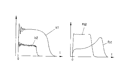
In Fig. 7, the temporal plot of a first short-circuit current id l for a
permanent, or 50/50 PWM
short circuit and a second short-circuit current ic2 generated according to
the invention, is
shown. For the first short-circuit current id l a maximum short circuit phase
tc_ks chosen, i.e.
a permanent phase A. In the lower part of Fig. 7 there is a temporal plot of a
first braking
force Fbl which results from the first short-circuit current id l and a
temporal plot of a second
braking force Fb2, which results from the second short-circuit current 1c2. It
can be seen that
the second braking force Fb2 is higher than the first braking force Fbl
directly after the start
of the braking operation, although the second short-circuit current ic2 is
less than the first
short-circuit current id, a situation which results from an increased driving
force-forming
short-circuit current component icq in accordance with the invention. In
addition, the vibration
behavior of the second short-circuit current ic2 is improved.
The selection of the drive coils Sm controlled according to the controlled
short-circuit mode
M, can be fundamentally free. Thus, all drive coils Sn or some of the drive
coils Sn can be
switched to the controlled short-circuit mode M. Advantageously, the
magnetically-coupled
drive coils Sm can be switched to the controlled short-circuit mode M using
the transport unit
TI.
Which drive coils Sm are coupled to the transport unit 1 can be determined via
the current
position of the transport unit 1. This position detection can take place by
means of suitable
position sensors, which may already be provided on the long-stator linear
motor, for example
as described in AT 519 238 Al.
However, which coils Sm in the short-circuited state drive a coil short-
circuit current icm
(which is measured) can also be detected. From this it can be concluded which
of the drive
coils Sm are magnetically coupled to the transport unit 1.
If it is detected that the transport unit 1 continues to move during the
braking operation in
such a way that a further drive coil Sm present in the direction of motion x
is coupled to the
transport unit 1 (e.g. since a coil short-circuit current icm is induced),
then this drive coil Sm
can also be switched to the short-circuit mode M. As a rule, this has the
consequence that a
drive coil Sm is no longer coupled to the transport unit 1 counter to the
direction of motion x,
so that it no longer has to remain in short-circuit mode M. However, the fact
that the drive coil
Sm is no longer coupled to the transport unit 1 counter to the direction of
motion x can also
be detected via position sensors or via the non-induction of a coil short-
circuit current icm. It
-12-
CA 3045839 2019-06-11
can be seen that the last drive coil Sm coupled counter to the direction of
motion x is no
longer coupled to the transport unit 1, which indicates that the next coil Sm
located in the
direction of motion x is operated in the short-circuit mode M instead of the
first-mentioned
drive coil Sm.
Advantageously, the short-circuit current ic can be limited, for example to a
threshold value
icmax, by the short-circuit controller K. This can be done by switching from
short circuiting to
idle. Thus, it is possible to control the (average) short-circuit current ic -
as long as enough
kinetic energy is present in the transport unit 1.
-13-
CA 3045839 2019-06-11