Note : Les descriptions sont présentées dans la langue officielle dans laquelle elles ont été soumises.
CA 03047116 2019-06-13
WO 2018/112341
PCT/US2017/066671
IN THE UNITED STATES PATENT AND TRADEMARK OFFICE
Alexandria, Virginia
PCT PATENT APPLICATION for
OPEN COIL SPRING ASSEMBLIES
CLAIM TO PRIORITY
100011 This PCT Patent Application claims priority to and benefit of, U.S.
Provisional Patent
Application Serial Number 62/434168, filed December 15, 2016 and titled "Open
Coil Spring
Assemblies", all of which is incorporated by reference herein.
TECHNICAL FIELD
100021 The present embodiments relate to open coil spring assemblies which
have
performance like pocketed coil assemblies. In particular, the present
embodiments
relate to open coil spring assemblies that make use of an elastic lacing,
elastic
connections or other connecting methods and structures to join together a
plurality
of open coil springs in a manner that improves compliance, reduces motion
transfer and bounce across the plurality of open coil springs and allows each
of the
open coil springs to move more independently of one another.
BACKGROUND
10003] In an open spring assembly of a mattress core, open innersprings,
which are
also referred to as open coil springs, have traditionally been attached to one
another
using a helical wire lacing mechanism. In particular, in such an assembly, the
helical wire lacing mechanism joins each row of open coil springs together and
thereby sets the spacing of each spring segment to fairly fixed and rigid
locations.
Some flexure of the helical wire lacing mechanism is allowed in such spring
assemblies and allows for some degree of conformity of the coil springs in the
assembly with a user's body. However, the rigid wire lacing of the coil
springs is
generally regarded as serving to reduce that conformity.
100041 In this regard, traditional spring assemblies comprised of a
plurality of open
coil springs have also suffered from excessive motion transfer due to the
connectivity provided by the lacing of the open coil springs with a helical
wire
CA 03047116 2019-06-13
WO 2018/112341
PCT/US2017/066671
mechanism in the form of rigid steel helical wires. One alternative to those
rigid
spring assemblies has been spring assemblies that include a plurality of
pocketed
coil springs, as such pocketed coil springs typically exhibit a greater
independence
as the various pocketed coils are generally loosely connected by using a
fabric
pocket that is welded and glued together. Nevertheless, open coil springs
remain
significantly more economical to produce and are thus often regarded as more
desirable from a production standpoint. Accordingly, a coil spring assembly
design that uses open coil springs, but yet performs in the same manner as a
pocketed coil spring would be both highly desirable and beneficial.
100051 The information included in this Background section of the
specification,
including any references cited herein and any description or discussion
thereof, is
included for technical reference purposes oril and is not to be regarded
subject matter
by which the scope of the invention is to be bound.
SUMMARY
[00061 According to some object and/or embodiments, an open coil spring
assembly may comprise a plurality of rows of open coil springs arranged to
form a
matrix of the open coil springs, each of the open coil springs including an
upper
end convolution and a lower end convolution, and, an elastic lacing extending
between pairs of adjacent rows of the plurality of rows of open coil springs,
the
elastic lacing attached to the upper end convolution of each of the open coil
springs
in one of the plurality of rows of open coils springs and to the upper end
convolution of each open coil spring in an adjacent one of the plurality of
rows of
open coil springs.
100071 According to some optional embodiments any of the following may be used
with the first embodiment either alone or in any of various combinations. The
elastic
lacing may comprise a shock cord. The upper end convolution of each open coil
spring may include a notch for attaching the upper end convolution of each
open coil
spring to the elastic lacing. The open coil spring may further comprise a clip
for
attaching the upper end convolution of each open coil spring to the elastic
lacing. The
open coil spring assembly may further comprise a helical wire extending
between
each of the plurality of rows of open coil springs, wherein the helical wire
may be
attached to the lower end convolution of each of the open coil springs in one
of the
2
CA 03047116 2019-06-13
WO 2018/112341
PCT/US2017/066671
plurality of rows of open coil springs and to the lower end convolution of
each open
coil spring in an adjacent one of the plurality of rows of open coil springs.
Each of
the open coil springs in one of the plurality of rows of open coils springs
may be
offset from each of the open coil springs in an adjacent one of the plurality
of rows of
open coil springs. The elastic lacing may comprise a wire having a first
portion
including a plurality of helical convolutions attached to each of the open
coil springs
in a respective one of the plurality of rows of open coils springs, and a
second portion
including a plurality of helical convolutions extending between each of the
open coil
springs in the respective one of the plurality of rows of open coil springs.
The
plurality of helical convolutions in the first portion may defme a first pitch
between
each of the plurality of helical convolutions in the first portion, and
further wherein
the plurality of helical convolution in the second portion defines a second
pitch
between each of the plurality of helical convolutions in the second portion,
and
wherein the first pitch is greater than the second pitch. The open coil spring
assembly
may further comprise an additional wire extending between each of the
plurality of
rows of open coil springs, the additional wire may be attached to the lower
end
convolution of each of the open coil springs in one of the plurality of rows
of open
coil springs and to the lower end convolution of each coil spring in an
adjacent one of
the plurality of rows of open coil springs, the additional wire may have a
first portion
including a plurality of helical convolutions attached to each of the open
coil springs
in a respective one of the plurality of rows of open coils springs, and a
second portion
including a plurality of helical convolutions extending between each of the
open coil
springs in the respective one of the plurality of rows of open coil springs.
The
plurality of helical convolutions in the first portion of the additional wire
define a first
pitch between each of the plurality of helical convolutions in the first
portion of the
additional wire. Further, the plurality of helical convolutions in the second
portion of
the additional wire define a second pitch between each of the plurality of
helical
convolutions in the second portion of the additional wire. The first pitch may
be
defined by the plurality of helical convolutions in the first portion of the
additional
wire is greater than the second pitch defined by the plurality of helical
convolutions in
the second portion of the additional wire. The elastic lacing may comprises a
plurality of discrete flexible bands, and wherein the upper end convolution of
each of
the open coil springs in the one of the plurality of rows of open coil springs
is
3
CA 03047116 2019-06-13
WO 2018/112341
PCT/US2017/066671
attached to the upper end convolution of each of the open coil springs in the
adjacent
one of the plurality of rows of open coil springs by one of the plurality of
discrete
flexible bands. The open coil spring assembly may further comprise a discrete
flexible band connecting the upper end convolution of each open coil spring in
a
respective one of the rows of open coils springs to the upper end convolution
of an
adjacent open coil spring in the respective row. The open coil spring assembly
may
further comprising an additional plurality of discrete flexible bands, and
wherein the
lower end convolution of each of the open coil springs in the one of the
plurality of
rows of open coil springs is attached to the lower end convolution of each of
the open
coil springs in the adjacent one of the plurality of rows of open coil springs
by one of
the additional plurality of discrete flexible bands. The open coil spring
assembly may
further comprise a discrete flexible band connecting the lower end convolution
of
each open coil spring in a respective one of the rows of open coils springs to
the lower
end convolution of an adjacent open coil spring in the respective row. The
open coil
spring assembly may further comprising a damper extending through said springs
at a
position between the lower end convolution and the upper end convolution. The
open
coil spring assembly wherein the damper is arranged horizontally and engages a
plurality of springs in one of a direction of a row or perpendicular to a row.
The open
coil spring assembly of claim 15, wherein the damper is arranged vertically
within the
matrix and one of extends through at least one of the coils springs or is
spaced from
the coil springs.
[00081 The open coil spring assembly may further comprise two elastic
lacings
between each of the adjacent rows of the plurality of springs. The two elastic
lacings
between each of the adjacent rows may have one of parallel paths or serpentine
paths.
The elastic lacings may extend in a single direction. The elastic lacings may
extend in
two directions. The elastic lacings may be disposed at an angle to the
plurality of
rows of open coil springs. The elastic lacing may extend through a vertical
dimension. The elastic lacing may compress at least some of the open coil
springs of
each of the plurality of rows. The open coil springs are multistage springs
having a
first portion with a first pitch and a second portion with a second pitch. The
open coil
spring may further comprise the second spring portion disposed above the first
portion
of the coil spring. The second spring portion may have at least one of a
differing
shape or pitch. The elastic lacing is disposed near a bottom of the second
spring
4
CA 03047116 2019-06-13
WO 2018/112341
PCT/US2017/066671
portion. The coil spring assembly may further comprise a foam layer disposed
over
the second spring portion. The foam may have a cut out to receive the second
spring
portion. The elastic lacing may be disposed at a top of the second spring
portion. The
open end coil springs may have at least two pitches. The upper end convolution
of
the open end coil springs may differ in shape than convolutions below the
upper end
convolution. The upper end convolution may be of a generally polygonal shape.
The
upper end convolutions may comprise wings. The upper end convolution bends
downward toward an adjacent convolution. The coil spring assembly may further
comprise clips which may connect one or more open end coils and which may
extend
in one or more directions.
[0009] According to another embodiment, an open coil spring assembly may
comprise
a plurality of open coil springs arranged to form a matrix of open coil
springs, the
matrix of open coils springs including a plurality of rows of open coils
springs and a
plurality of columns of open coil springs, each of the open coil springs
including an
upper end convolution and a lower end convolution, a first metal strip
extending along
and attached to the upper end convolution of each of the open coil springs in
a
respective one of the rows of open coils springs, the first metal strip
including a V-
shaped flexure extending between each of the open coil springs in the
respective one
of the rows of open coils springs, and, a second metal strip extending in a
direction
perpendicular to the first metal strip and attached to the lower end
convolution of each
of the open coil springs in a respective one of the columns of open coils
springs, the
second metal strip including a V-shaped flexure extending between each of the
open
coil springs in the respective one of the columns of open coils springs.
[0010] According to a further embodiment an open coil spring assembly may
comprise
a first plurality of open coil springs arranged in a first row, a second
plurality of open
coil springs arranged in a second row, which is parallel to the first row,
each spring of
the first and second plurality of open coil springs having at least one an
integrally
formed connector extending to another of the springs, and, the integral
connectors
providing a pivoting connection between adjacent open coil springs of the
plurality of
open coil springs of the first row and the second row.
[0011] Optionally, in combination with the previous embodiment, either
alone or in
combination, the following may be utilized. The open coil springs may have an
upper
convolution having a first bar and a second bar. The first bar and the second
bar may
CA 03047116 2019-06-13
WO 2018/112341
PCT/US2017/066671
have cooperating shapes which may interlace. The first bar of one of the
adjacent
springs interlacing with the second bar of said adjacent springs.
100121 All of the above outlined features are to be understood as exemplary
only and
many more features and objectives of an open coil spring assembly may be
gleaned
from the disclosure herein. Therefore, no limiting interpretation of this
summary is to
be understood without further reading of the entire specification, claims and
drawings,
included herewith
BRIEF DESCRIPTION OF THE DRAWINGS
[0013] In order that the embodiments may be better understood, embodiments
of the
open coil spring assembly will now be described by way of examples. These
embodiments are not to limit the scope of the claims as other embodiments of
the
open coil spring assembly will become apparent to one having ordinary skill in
the art
upon reading the instant description. Non-limiting examples of the present
embodiments are shown in figures wherein
[0014] FIG. IA is a perspective view of an open coil spring assembly made
in
accordance with the present invention;
[0015] FIG. 1B is a partial top view of the open coil spring assembly of
FIG. 1A;
[0016] FIG. IC is a side view and a top view of an open coil spring
utilized in the
open coil spring assembly of FIG. IA;
[0017] FIG. 2A is a perspective view of another open coil spring assembly
made in
accordance with the present invention;
[0018] FIG. 2B is a side view of a row of open coil springs included in the
open
coil spring assembly of FIG. 2A;
[0019] FIG. 3A is a perspective view of another open coil spring assembly
made in
accordance with the present invention;
[0020] FIG. 3B is a partial perspective view of the open coil spring assembly
of
FIG. 3A;
[0021] FIG. 4 is a perspective view of another open coil spring assembly
embodiment;
[0022] FIG. 5 is a perspective view of another assembly embodiment with an
exploded detail of an illustrative spring of the assembly;
6
CA 03047116 2019-06-13
WO 2018/112341
PCT/US2017/066671
[0023] FIG. 6 is a perspective view of another open coil spring assembly
embodiment
with an exploded detail view of a portion of the assembly;
[0024] FIG. 6A is a detail view of an alternate embodiment wherein the
damper
extends through the open end coil spring;
[0025] FIG. 7 is a perspective view of another assembly embodiment having
multiple
elastic lacings between rows;
[0026] FIG. 7A is a top view of the embodiment of FIG. 7 further depicting
the
elastic lacings;
[0027] FIG. 7B is a top view of an further alternate arrangement of the
multiple
elastic lacing embodiment;
[0028] FIG. 7C is a top view of still a further arrangement of springs and
elastic
lacing of an alternate embodiment;
[0029] FIG. 8A is a perspective view of an open coil spring assembly
having dampers
disposed through the spring matrix;
100301 FIG. 9 is a perspective view of an illustrative open coil spring
assembly
having alternate arrangement of elastic lacing;
[0031] FIGS. 10- 10A show various embodiments of bar-to-bar configurations
of the
open coil spring assembly which allow for hinging between adjacent coils;
[0032] FIG. 11 is an alternate embodiment of a bar-to-bar configuration of
springs
which allows interconnection of the springs and hinging therebetween;
[0033] FIG. 12 is a side view of two alternate rows of springs which may
be utilized
with an elastic lacing which varies the height of springs in each row,
[0034] FIG. 13 is an alternate embodiment of that shown in FIG. 12 wherein
elastic
lacing may extend through a vertical dimension improve spring performance;
[0035] FIG. 14 is a further alternate embodiment of elastic lacings which
provide
multi-stage performance by using different materials and/or sizes which extend
through a vertical dimension;
[0036] FIG. 15 is another embodiment of open coil spring assembly with
multi-stage
springs;
100371 FIG. 16 is a further embodiment of FIG. 15 with an upper foam
layer;
100381 FIG. 17 is an alternate embodiment of a spring assembly and an
exploded
detail of one spring having a polygonal convolution end; and,
7
CA 03047116 2019-06-13
WO 2018/112341
PCT/US2017/066671
[0039] FIG. 18 is another alternate spring assembly with an alternative
convolution
end.
DESCRIPTION OF EXEMPLARY EMBODIMENTS
[0040] It is to be understood that the open coil spring assembly is not
limited in its
application to the details of construction and the arrangement of components
set forth
in the following description or illustrated in the drawings. The invention is
capable of
other embodiments and of being practiced or of being carried out in various
ways.
Also, it is to be understood that the phraseology and terminology used herein
is for the
purpose of description and should not be regarded as limiting. The use of
"including,"
"comprising," or "having" and variations thereof herein is meant to encompass
the
items listed thereafter and equivalents thereof as well as additional items.
Unless
limited otherwise, the terms "connected," "coupled," and "mounted," and
variations
thereof herein are used broadly and encompass direct and indirect connections,
couplings, and mountings. In addition, the terms "connected" and "coupled" and
variations thereof are not restricted to physical or mechanical connections or
couplings.
[0041] The present embodiments comprise open coil spring assemblies for
support
cushions, such as mattresses. In particular, the present embodiments comprise
open
coil spring assemblies that make use of an elastic lacing or other connecting
methods, which may be of various forms, to join together a plurality of open
coil
springs in a manner that reduces motion transfer and bounce across the
plurality of
open coil springs and allows each of the open coil springs to move more
independently of one another. Thus, in some embodiments, the open coil spring
assemblies of the present invention replaces the top helical lacing wire found
in
conventional open coil spring assemblies and replaces that top helical lacing
wire
with an elastic lacing, elastic connection or other connecting methods, which
may
be of various forms embodied herein. By adding elasticity to the lacing or by
using
alternative connecting methods, the individual coils in an exemplary open coil
spring assembly become more independent from one another and behave in manner
similar to that observed in pocketed coil spring assemblies. Other embodiments
maintain a helical lacing but provide alternate structures to achieve the
above
referenced functional improvements.
8
CA 03047116 2019-06-13
WO 2018/112341
PCT/US2017/066671
100421 These improvements may relate to, but are not limited to,
variations of
springs or alternative attachment methods joining coils other than traditional
lacing
methods, aligning or offsetting of the springs in one or more dimensions or
rows,
pre-loading of springs, joining of springs and/or the elastic lacing and other
embodiments provided herein or variations thereof.
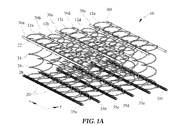
100431 Referring first to FIGS. 1A-1C, in one exemplary embodiment of the
present invention, an open coil spring assembly 10 is provided that comprises
a
plurality of rows 12a, 12b, 12c, 12d, 12e of open coil springs 20 that are
arranged
to form a matrix. The plurality of rows may be defined in a single dimension,
such as the X-dimension, the Y-dimension, or may also be defined in both of
the
X, Y dimensions. Further, the X-dimension and Y-dimension may be either of
the head-to-toe direction of the bed or the side-to-side direction of the bed,
for
example. The number of rows may vary depending on a desired assembly size.
Each of the open coil springs 20 included in the open coil spring assembly 10
has
an upper end convolution 22, a lower end convolution 28, and a plurality of
helical convolutions 24, 26 that extend between the upper end convolution 22
and
the lower end convolution 28 of each open coil spring 20. Segments of elastic
lacing 30a, 30b, 30c, 30d, 30e, 30f are further included in the exemplary open
coil
spring assembly 10 and extend between each of the plurality of rows 12a, 12b,
12c, 12d, 12e of open coil springs 20. More specifically, each segment of
elastic
lacing 30a, 30b, 30c, 30d, 30e, 30f is attached to the upper end convolution
22 of
each of the open coil springs 20 in one of the plurality of rows 12a, 12b,
12c, 12d,
12e of open coil springs 20 and to the upper end convolution 22 of each open
coil
spring 20 in an adjacent one of the plurality of rows 12a, 12b, 12c, 12d, 12e
of open
coil springs 20, as perhaps shown best by the two rows 12a, 12b of open coil
springs
20 connected by the elastic lacing 30c illustrated in FIG. 1B.
100441 With further respect to the exemplary open coil springs 20 included
in the
open coil spring assembly 10, each open coil spring 20 is generally a five and
one-
half turn spring with three and one-half active turns as the added half turn
is
believed to allow each open coil spring 10 to remain more upright and to also
allow
each open coil spring 20 to be easily attached to one of the segments of
elastic
lacing 30a, 30b, 30c, 30d, 30e, 30f. Moreover, the diameter of each of the
open coil
springs 20 shown in FIGS. 1A-1C generally has a diameter of about two inches
that
9
CA 03047116 2019-06-13
WO 2018/112341
PCT/US2017/066671
expands to two and one-half inches at both the upper end convolution 22 and
the
lower end convolution 28 to impart additional vertical stability to each of
the open
coil springs 20 and to allow each of the open coil springs 20 to remain more
upright
as lateral forces push against the top of each of the open coil springs 20. Of
course,
open coil springs have various other numbers of turns and diameters can also
be
produced, and can be selected for a particular application without departing
from
the spirit and scope of the present invention. With regard to the sizes of
upper end
convolution 22 and the lower end convolutions 28 of the coil spring 20, where
the
diameter, or distance across if not circular, at the top 22 of the spring 20
and the
bottom 28 of the spring differ, the greater the difference between diameters
at the
top and bottom may provide greater stretching length for lacing, and therefore
more
compliance. Alternatively, where the diameters are the same or closer in
measurement, this design may decrease the amount of compliance, if desirable.
In
some embodiments, the springs 20 may be conical in shape and in some other
embodiments the spring may be cylindrical. However, still other shapes may be
utilized with review of compliance and stability. Likewise, the cylindrical
shape
and the conical shape may be fully circular, or may be partially circular with
sections of spring that are not circular, such as at the top convolution 22
and/or
bottom convolution 28 of each spring. Various spring designs may be utilized
and
where a spring diameter decreases, the spring may be stiffened. Alternatively,
where larger diameters are utilized, the spring may be softened.
[00451 To provide a point of attachment in the upper end convolution 22 of
each
open coil spring 20 for attaching each open coil spring 20 to one of the
segments of
elastic lacing 30a, 30b, 30c, 30d, 30e, 30f, each open coil spring 20 may also
include
a pair of notches 43a, 43b in the upper end convolution 22 of each open coil
spring
20. Each of the notches 43a, 43b is essentially comprised of a flattened
portion of
the upper end convolution 22 of each open coil spring 20 that extends beyond
the
circumference of the upper end convolution 22 to not only provide a flattened
point
of attachment for a respective one of the segments of elastic lacing 30a, 30b,
30c,
30d, 30e, 30f, but to also, at least in part, ensure adequate spacing between
neighboring open coil springs 20 and reduce noise caused by spring-to-spring
contact. In the exemplary embodiment, to allow for such attachment and
spacing, the
width of each of the notches 43a, 43a is typically in the range of about 3/8
inches,
CA 03047116 2019-06-13
WO 2018/112341
PCT/US2017/066671
but, again, such a dimension can readily be adapted for a specific spring or
application as desired. Additionally, each of the notches 43a, 43b may be
sized
corresponding to a clip 50 size which is used to connect each spring to the
elastic
lacing 30 or to connect each spring to another spring. By sizing the notches
43a, 43b
in such manner as to correspond to the size of a clip 50 (FIG. 1B), the
movement of
the spring relative to the clip 50, or vice-versa may be limited.
100461 Turning now to the segments of elastic lacing 30a - 30f included in
the
spring assemblies, various elastic materials including metals, alloys, rubber,
latex,
thermoplastic polyurethane, and the like can be used as all or part of an
exemplary
segment of elastic lacing. In the exemplary open coil spring assembly 10, the
segments of elastic lacing 30a, 30b, 30c, 30d, 30e, 30f are comprised a shock
cord.
As such, each of the segments of elastic lacing 30a, 30b, 30c, 30d, 30e, 30f
thus
typically includes a protective outer nylon woven sheath that limits the
amount of
deflection of each of the segments of elastic lacing 30a, 30b, 30c, 30d, 30e,
30f and
further includes an inner elastic portion, which is comprised of a durable
latex or
other comparable material, that is capable of withstanding little to no
degradation
in modulus after multiple cycles.
100471 The elastic lacing or elastic connections as described in the
instant
application may take various forms. For example, with respect to the segments
of elastic lacing 30a, 30b, 30c, 30d, 30e, 30f included in the open coil
spring
assembly 10, and without wishing to be bound by any particular theory or
mechanism, it is believed that, in certain embodiments, a balance of wire
diameter (gauge) and diameter of the segments of elastic lacing 30a, 30b, 30c,
30d, 30e, 30f (e.g., the shock cord or bungee cord, for example) can be taken
into consideration to both decrease motion transfer and bounce, such as what
may occur if the ratio becomes too low (i.e. with a larger shock cord) and the
stiffness of the assembly increases, and to prevent the spring from bottoming
out
and having an unstable surface, such as what may occur if the ratio is too
high. In
this regard, in the exemplary open coil spring assembly 10, each of the open
coil
springs 20 is formed from a continuous wire having a diameter of 0.083 inches
and segments of elastic lacing 30a, 30b, 30c, 30d, 30e, 30f (i.e., segments of
shock
cord) having a diameter of 0.25 inches, such that the ratio of wire diameter
(gauge) and diameter of the segments of elastic lacing 30a, 30b, 30c, 30d,
30e, 30f
11
CA 03047116 2019-06-13
WO 2018/112341
PCT/US2017/066671
in the open coil spring assembly 10 is 0.332. Shock cord may be similar to
bungee-cord-like material in some embodiments, but may be formed of various
materials which provide flexibility and elasticity including, but not limited
to,
latex, polyurethane elastomer, plastics, rubbers, metals, alloys and/or
combinations of any of such or other materials as well, all of which may be
utilized. Further however, as will be shown in other embodiments, the elastic
lacing may take other forms which provide a steadying connection between the
coil springs of the assembly, either directly or indirectly.
[0048] To attach the segments of elastic lacing 30a, 30b, 30c, 30d, 30e,
30f to the
upper end convolutions 22 of each of the open coil springs 20, the open coil
spring
assembly 10 further includes a plurality of clips 50. Each of the clips 50 is
typically in the form of a three-eighths (3/8") of an inch brass or other
materials
for crimping, which allows the clips 50 to be soft enough to easily crimp
around a
respective one of the notches 43a, 43b in each upper end convolution 22 of
each of
the open coil springs 20 and a respective one of the segments of elastic
lacing 30a,
30b, 30c, 30d, 30e, 301 but also allows each of the clips to provide enough
compressive force to not allow the segments of elastic lacing 30a, 30b, 30c,
30d,
30e, 30f to slip along the upper end convolutions 22 of each of the open coil
springs 20. In this regard, each of the segments of elastic lacing 30a, 30b,
30c,
30d, 30e, 30f is generally attached to the upper end convolution 22 of each of
the
open coil springs 20 below the upper surface of the springs to prevent each of
the
segments of elastic lacing 30a, 30b, 30c, 30d, 30e, 30f from working itself
under
one of the open coil springs 20 as it is being compressed downward. The
elastic
lacings 30a - 30f may further comprise a preselected shape at locations where
the
notches are located to engage the notches 43a, 43b and aid in retention of the
open
coil springs 20 in position relative to the elastic lacings 30a - 30f.
[0049] Referring still to FIGS. 1A-1C, to attach the lower end
convolutions 28 of
the open coil springs 20 together, the open coil spring assembly 10 further
comprising a plurality of lower helical lacing wires 35a, 35b, 35c, 35d, 35e,
35f that
also extend between each of the plurality of rows 12a, 12b, 12c, 12d, 12e, 12f
of
open coil springs 20. Each of the lower helical wires 35a, 35b, 35c, 35d, 35e,
35f
are attached to the lower end convolution 28 of each of the open coil springs
20 in a
respective one of the plurality of rows 12a, 12b, 12c, 12d, 12e, 12f of open
coil
12
CA 03047116 2019-06-13
WO 2018/112341
PCT/US2017/066671
springs 20 and to the lower end convolution 28 of each open coil spring 20 in
an
adjacent one of the plurality of rows 12a, 12b, 12c, 12d, 12e, 12f of open
coil
springs 20. By including such lower helical lacing wires 35a, 35b, 35c, 35d,
35e,
35f in the open coil spring assembly 10, the lower helical lacing wires 35a,
35b,
35c, 35d, 35e serve to maintain the geometric shape of each open coil spring
20
and, in turn, the open coil spring assembly 10, as well as prevent the lower
portion of each open coil spring 20 from moving independently.
[0050] In order for each of the open coil springs 20 to maintain
independence
from one another, each of the open coil springs 20 are also generally offset
from
one another such that the clips 50 alternate from side-to-side along the
length of
the segments of elastic lacing 30a, 30b, 30c, 30d, 30e, 30f. Offsetting each
of the
open coil springs 10 also provides for sufficient spacing between open coil
springs 20 so as to minimize coil-to-coil collisions. In some embodiments, any
instabilities of the individual open coil springs 20 may also be minimized
further
by rotating each row 12a, 12b, 12c, 12d, 12e, 12f of open coil springs 20 by,
some amount, for example 180 . Such a rotation improves stability by
cancelling
any lean left in the spring geometry due to the forming process and by
allowing
any lean to be cancelled by virtue of coupling the lean with an opposing lean
in
the opposite direction. However, the matrix defined by the rows may provide a
single row direction of spring alignment, and be offset in a second,
perpendicular
direction, or alternatively, may comprise the second, perpendicular rows be
aligned. Thus row arrangement may be a single direction or two directions for
any of the embodiments of the instant disclosure. Likewise, the spring
rotation,
for example about a vertical axis, may also be a design characteristic of any
of
the embodiments.
[0051] As a refinement to the open coil spring assemblies of the present
invention,
various other configurations of an elastic lacing can also be used to allow
the
individual coils in an exemplary open coil spring assembly to move more
independently from one another and behave in a manner similar to that observed
in
pocketed coil spring assemblies. For example, as a refinement and referring
now
to FIGS. 2A-2B, in another exemplary embodiment, an open coil spring assembly
110 is provided that, like the exemplary open coil spring assembly 10 shown in
FIGS. 1A-1C, includes a plurality of rows 112a, 112b, 112c of open coil
springs
13
CA 03047116 2019-06-13
WO 2018/112341
PCT/US2017/066671
120 that are arranged to form a matrix In this embodiment the coil springs of
an
adjacent row, for example row 1121), may or may not be offset from row 112a in
an X-direction, so that rows in a Y-direction may or may not be also defined.
In
the instant embodiment, the adjacent rows, for example 112b, are generally not
offset in the X-direction. Each of the open coil springs 120 included in the
open
coil spring assembly 110 also similarly has an upper end convolution 122, a
lower
end convolution 128, and a plurality of helical convolutions 124, 125, 126,
127
that extend between the upper end convolution 122 and the lower end
convolution
128 of each open coil spring 120. Unlike the open coil spring assembly 10
shown
in FIGS. 1A-1C, however, the open coil spring assembly 110 does not make use
of
elastic lacing that is in the form of a shock cord. Rather, in the open coil
spring
assembly 110, the elastic lacing is comprised of a segments of wire 130a,
130b,
130c, 130d, with each of the segments of wire 130a, 130b, 130c, 130d having a
first portion 132 including a plurality of helical convolutions attached to
each of
the open coil springs 120 in a respective one of the plurality of rows 112a,
112b,
112c of open coils springs 20, and a second portion 131 including a plurality
of
helical convolutions extending between each of the open coil springs 20 in the
respective one of the plurality of rows 112a, 112b, 112c of open coil springs
120.
In this regard, to provide independence between the open coil springs 120, the
plurality of helical convolutions in the first portion 132 defines a first
pitch
between each of the plurality of helical convolutions in the first portion 132
that is
different from the pitch of the second portion 131. For example, in some
embodiments the pitch of first portion 132 may be greater than the pitch
defined
by and between the plurality of helical convolutions in the second portion
131, or
vice versa. One of the first portion 132 and second portion 131 of
convolutions
may be used to capture or engage the coil springs 120, for example, the
notches
43a, 43b of the coil springs 120. Additionally, by using such variable pitch,
the
spacing of the coil springs 120 of the open coil spring assembly 110 may also
be
controlled.
100521 To further ensure that the each of the open coil springs 120 move
more
independently from one another in the open coil spring assembly 110, the open
coil
spring assembly 110 further comprises additional lower segments of wire 135a,
135b,
135c, 135d that extend between each of the plurality of rows 112a, 112b, 112c
of
14
CA 03047116 2019-06-13
WO 2018/112341
PCT/US2017/066671
open coil springs 20 and that are attached to the lower end convolution 128 of
each of
the open coil springs 120 in one of the plurality of rows 112a, 112b, 112c of
open coil
springs 120 and to the lower end convolution 128 of each open coil spring 120
in an
adjacent one of the plurality of rows 112a, 112b, 112c of open coil springs
120. in
particular, and similar to the segments of wire 130a, 130b, 130c, 130d
attached to
the upper end convolutions 122 of the open coil springs 120, the additional
segments of wire 135a, 135b, 135c, 135d include a first portion 137 having a
plurality of helical convolutions attached to each of the open coil springs
120 in a
respective one of the plurality of rows 112a, 112b, 112c of open coils springs
120,
and a second portion 136 including a plurality of helical convolutions
extending
between each of the open coil springs 120 in the respective one of the
plurality of
rows 112a, 112b, 112c of open coil springs 120, with the pitch defined by the
convolutions in the first portion 137 being greater than that of the second
portion
136.
100531 As another refinement, in other embodiments of the open coil spring
assemblies of the present invention, the helical wires that have
conventionally
connected the individual open coil springs in a traditional open coils spring
assembly can also be replaced with individual flexible connectors, which can
then
stretch and bend to provide an additional layer of independence by allowing
each
open coil spring to move more freely, but yet still attaching each open coil
spring
to its neighbor. For instance, and referring now to FIGS. 3A-3B, in a further
embodiment, an open coil spring assembly 210 is provided that includes a
plurality
of rows 212a, 212b, 212c of open coil springs 220 that are arranged to form a
matrix. Each of the open coil springs 220 included in the open coil spring
assembly 210 has an upper end convolution 222 and a lower end convolution 228.
The open coil spring assembly 210 further includes an elastic lacing or
connections in the form of a plurality of discrete flexible bands 230 that
attach the
upper end convolution 222 of each of the open coil springs 220 in one of the
plurality of rows 212a, 212b, 212c of open coils springs 220 to the upper end
convolution 222 of each of the open coil springs 220 in the adjacent one of
the
plurality of rows 212a, 212b, 212c of open coil springs 220. One of the
plurality of
discrete flexible bands 230 further connects the upper end convolution 222 of
each
open coil spring 220 in a respective one of the rows 212a, 212b, 212c of open
coil
CA 03047116 2019-06-13
WO 2018/112341
PCT/US2017/066671
springs 220 to the upper end convolution 222 of an adjacent open coil spring
220 in
the same respective row 212a, 212b, 212c. Thus the bands 230 may extend in
both
the X and Y directions. An additional plurality of discrete flexible bands 235
then
also connects the lower end convolution 228 of each of the open coil springs
220 in
the same manner. The bands 230 may include ends which are sized to engage, for
example receive, end convolutions 222 and a central portion which extends
between
the ends. In the non-limiting embodiment, the ends may be circular in cross-
section
with a hollow area to receive the convolution ends. In this embodiment, the
flexible
bands 230 allow for normal deflection of the coil springs 220, up to a certain
amount
of deflection. Then, the flexible bands 230 limit deflection beyond the
threshold
amount.
100541 As an even further refinement, in further embodiments of the
present
invention, open coil spring assemblies are also provided that make use of
metal
strips including flexures that provide a hinge-like flexing motion between
open
coil springs to give more independence to each open coil spring. As one
example
of such an embodiment, and referring now to FIG. 4, an exemplary open coil
spring assembly 310 is provided that includes a plurality of open coil springs
320
arranged to form a matrix. The matrix of open coil springs 320 includes a
plurality of rows 312 of the open coils springs 320 as well as a plurality of
columns 314 of the open coil springs 320. A plurality of first metal strips
331 are
further included and extend along and are attached to the upper end
convolution
322 of each of the open coil springs 320 in a respective one of the rows 312
of the
open coil springs 320. Each of the first metal strips 331 includes a V-shaped
flexure 332 that extends between each of the open coil springs 320 in the
respective one of the rows 312 of open coil springs 320 to give more
independence to each open coil spring 320. A second metal strip 335 is also
included and has a plurality of V-shaped flexures 336. The second metal strip
335
extends in a direction perpendicular to the first metal strip 331 and is
attached to
the lower end convolution 328 of each of the open coil springs 320 in a
respective
one of the columns 314 of open coil springs 320 with each of the V-shaped
flexures 336 extending between each of the open coil springs 320 in the
respective one of the columns 314 of open coil springs 320.
16
CA 03047116 2019-06-13
WO 2018/112341
PCT/US2017/066671
[0055] In alternative embodiments, variations of the previously described
embodiments and features may be utilized. For example, the coil springs
according to some embodiments may be some shape other than helical. According
to some other embodiments, where a clip structure is utilized, a layer of foam
or
rubber may be utilized about the clip end of the springs, or alternatively the
entire
spring may be coated with the foam or rubber. The foam or rubber layer may not
only protect in the areas of clipping, but may also provide desired damping
for the
coil springs. Further, the sizes of the springs may vary. For example, the
spring
size may be large enough that elastic lacing is not required, but instead the
springs
engage one another. Still further the coil spring may comprise coil in coil
designs
according to some embodiments. Likewise, any of the previously described
features may be formed of a variety of materials in order to vary the
performance
characteristics of the assembly.
[0056] With reference now to FIG. 5, a further spring embodiment is
provided
which improves compliance and motion transfer performance. In this view a
perspective view of an assembly 410 is provided with an exploded detail view.
The assembly 410 is defined by a plurality of rows 412 which may be defined in
either or both of the X and Y directions. In the instant embodiment, each of
the
coil springs 420 may be a multi-stage spring with a first helical pitch and a
second
helical pitch. The coil spring 420 has a first helical portion 421, for
example a
lower portion with the first helical pitch and a second, upper helical portion
423
with the second helical pitch. Likewise, it should be understood that the
first
portion may be the upper portion and the second portion may be the lower
portion.
The first and second pitches may be different to provide different performance
in
different stages of compression. Additionally, the upper spring may be of the
same diameter or size as the lower spring, or may be of a different size. In
the
instant embodiment, the upper helical portion 423 may be frusto-conical in
shape
to change from a larger lower diameter to a smaller upper diameter.
[0057] An elastic or wire lacing 430 may be disposed at a lower end of the
upper
helical 423, or alternatively the upper end of the lower helical 421. In this
embodiment wherein the spring 420 is formed of two portions, the lacing 430,
wire
or elastic, is not at the top of the spring. Instead the lacing 430, wire or
elastic, is
disposed between the upper and lower portions 423, 421. A lower lacing wire
435
17
CA 03047116 2019-06-13
WO 2018/112341
PCT/US2017/066671
may also be utilized which may be of a known type of stiff wire lacing or may
of
an elastic lacing as previously described. The upper lacing 430 may run in the
same direction as the lower lacing wire 435, as depicted in some embodiments,
or
may run in perpendicular directions from one another. Still further, the
lacing 430
may be disposed at the upper end of upper portion 423 as described later and
the
lacings may run in a single direction or more than one direction, and may be
aligned or angled relative to the rows.
[0058) Still further, it is shown in this embodiment that where the
elastic lacing is
moved downward from the top of the coil spring, the upper end of the spring is
free to move.
100591 Referring now to FIG. 6, a further embodiment is provided. An
innerspring assembly 510 is provided again by rows 512 of springs 520 wherein
the rows in one or two. X and Y dimensions, depending on whether a spring
offset
is desired for performance characteristics. In his embodiment, the elastic
lacings
may be defined by a plurality of straps or dampers 530 which are provided in
the
assembly. In some embodiments, the straps 530 may be provided within the coil
envelope or in other embodiments, the straps 530 may be provided outside the
coil
envelope. Also a combination of such arrangements may be utilized.
100601 The straps 530 extend generally in a vertical direction between the
lacing
of the rows 512, or between spring connections at the upper end convolutions
522
and the lower end convolutions 528. The straps 530 may be formed of flexible
materials, such as for non-limiting example, rubber, shock-cord or like
material,
polyurethane, or other flexible materials, or combinations of materials. In
this
way, the coil springs 520 are connected in some fashion to the lacing, which
may
be of a similar type as is known in the art, or may be of the elastic lacing
type
described in various embodiments of the instant application. The straps 530
may
be used to pre-load the coil springs 520 or to stretch the springs depending
on a
length used or further, alone or in combination, preload a lacing at top or
bottom
of the assembly 510. All of this is, again, to improve compliance while
reducing
bounce, which is common to open coil springs.
100611 With reference to FIG. 6A, the dampers 530 are shown alternatively
extending vertically through the springs 520. The dampers may be connected to
the wire, to the open coil springs 520 or both
18
CA 03047116 2019-06-13
WO 2018/112341
PCT/US2017/066671
[0062] Referring now to FIG. 7, a further embodiment of an assembly is
shown in
perspective view wherein the elastic lacing is varied. In this embodiment, an
assembly 610 is provided as in earlier embodiments by a plurality of rows 612
of
springs which may be aligned in one or both of the head-to-toe direction and
the
side-to-side direction.
100631 According to the top view of FIG. 7A, and in combination with FIG.
7,
there are two elastic lacings 630a, 630b between each row of springs. In the
instant embodiment, the spring assembly 610 is arranged with rows 612 formed
in
two directions since the springs 620 are aligned rather than offset. In this
embodiment, the elastic lacings 630a, 630b are connected by clips 650a at
locations between the rows (as best shown in FIG. 7A) and are each connected
to
the springs 620 as designated by 650b, for example along a centerlines of the
springs 620. In this arrangement, the elastic lacings 630a, 630b may spread
apart
to connect to the spring coils 620, but are clipped together between rows.
Thus,
the lacings 630a, 630b have a serpentine shape.
[0064] With reference to FIG. 7B, a further alternative embodiment is
provided.
In other embodiments, the elastic lacings 1630 are arranged two between each
row
1612 of springs 1620. The lacings 1630 may extend straight, parallel to one
another between each row 1612, without moving away from one another and
toward one another in the serpentine pattern. In this embodiment, the spring
convolutions 1622 may be varied in order to allow the parallel elastic lacings
between springs to continue in such straight manner. In this embodiment, where
the elastic lacings 1630 are straight, the assembly 1610 may have more
stability
from side-to-side. In the depicted embodiment of assembly 610 where the
elastic
lacing 630 is somewhat serpentine, the assembly of springs 620 and lacings 630
may be have more compliance and generally more support.
100651 In these embodiments, the clips 650, 1650 may be aligned in a
single
direction according to some embodiments, which is coaxial with the direction
that
the elastic lacings 630, 1630 extends. Still further, it may be that elastic
lacings
630, 1630 may also extend in a perpendicular direction to that which is shown,
or
both directions. Thus in some embodiments, the clips 650, 1650 may extend in
same or different directions within an assembly.
19
CA 03047116 2019-06-13
WO 2018/112341
PCT/US2017/066671
[0066] Still further, and with reference to FIG. 7C, in some embodiments,
a single
elastic lacing 2630 may be utilized between each row 2612 of the coil springs
2620, as opposed to two elastic lacings between rows. In the depicted
embodiment, the rows 2612 of springs 2620 may be formed between the elastic
lacings 2630. Accordingly, each side of a spring 2620 may be clipped to one
elastic lacing 2630.
[0067] With reference still to FIG. 7C, the embodiment provides that rows
extend
in a single direction but the coil springs are offset, rather than aligned, in
a second
direction. In this embodiment, a single elastic lacing 2630 is utilized and
one clip
2650 per spring may be utilized to connect the coils to the elastic lacings.
As
compared to the embodiments of FIG. 1A-1C, for example the clips 2650 of any
single spring 2620 may be offset, rather than aligned, across any spring 2620.
Further, wherein the coil springs 2620 are shown having circular convolutions,
the
embodiments may alternately have a plurality of shapes which may be consistent
or may vary at the upper and lower end convolutions.
[0068] According to still a further embodiment, and with reference to FIG.
8 and
FIG. 8a, a plurality of springs 720 defining assembly 710 may further comprise
dampers or stabilizers 730 which extend substantially horizontally. For
example,
the embodiment is provided having a plurality of rows of coil springs defined
in
one direction or two directions, to define an assembly 710. Extending through
the
rows 712 of coil springs 720 may be the damper 730 to provide lateral
stability,
reduce bounce and reduce motion transfer. In the instant embodiment, the
damper
730 may be formed of polyethylene or polyurethane, but this is not a limiting
embodiment, as other materials may be utilized. Further, the damper 730 may be
positioned at various heights of the coil spring 720. In some embodiments the
damper 730 may be placed lower in the spring height, in order to improve
lateral
stability at the base of the springs. However, the damper 730 may also be
positioned higher in the spring depending on the desired result and for
example,
where the additional stability is needed.
[0069] The geometry of the dampers 730 may also vary. It may be desirable
that
the dampers 730 fit between adjacent springs 720, along a line between rows
712
for example. The damper 730 for example may be shaped to extend further
radially into the convolutions of the matrix assembly. Accordingly, the shape
of
CA 03047116 2019-06-13
WO 2018/112341
PCT/US2017/066671
the damper 730 may be somewhat dependent upon the diameter of the coil springs
720 and the radius of the coil curvature.
100701 In further optional embodiments, an alternative damper or
stabilizer may be
utilized. As shown in FIG. 8a, the coils of adjacent rows may be connected by
an
elastic connector 1730 toward lower ends of the springs 720, or any height of
the
springs 720. The connectors 1730 may be at the same elevations or may be at
different elevations. These elastic connectors 1730 at lower elevations of the
springs 720 may also aid with stability of the spring bases. Further, the
elastic
connectors 1730 may be used with or without the dampers 730.
100711 Referring now to further embodiments shown in the perspective view
of
FIG. 9, an assembly 810 is depicted having a plurality of elastic lacings 830.
in
this embodiment, the lacings 830 extend in two directions to define a net 840.
As
previously discussed, the lacings may extend in a direction of the rows of
coil
springs. However, additionally, the lacings may extend in a perpendicular
direction to the first direction of lacing.
100721 Further, as shown in the depicted embodiment, the first direction
of the
lacing 830 may be at an angle to the rows 812 of coil springs 820. However,
the
lacings 831 may also in a second perpendicular direction. In the instant
embodiment the lacings 830, 831 are extending at 45 degrees to the rows and
perpendicular to one another. The lacings may be clipped to the coil springs
820
as in previous embodiments and such may be provided with upper end
convolutions at locations adjacent to the elastic lacings 830, 831.
100731 With reference not to FIG. 10, a further embodiment is provided
wherein a
bar-to-bar connection is made in which spring coils are abutting or nearly
abutting
one another, at upper convolutions or alternatively are axially aligned to
allow
hinging or pivoting between adjacent springs. In such embodiment, a lacing 38
may be utilized and the lacing may be helical for non-limiting example. The
lacing 38 may receive upper convolutions 922 portions of adjacent springs in
the
axial direction of, and within, the helical. With this co-axial arrangement of
adjacent springs in the helical lacing, the adjacent spring may form a hinge
in
combination with the helical lacing. With additional reference to FIG. 10A, in
some embodiments, the spring upper end convolutions 922 may have shapes that
cooperate or interlace with the upper convolutions of an adjacent spring. For
21
CA 03047116 2019-06-13
WO 2018/112341
PCT/US2017/066671
example, in various profiles of FIG. 10A, the upper most bar of each spring
depicted convolution has a shape which cooperates with the lower bar shape of
the
convolution. When two springs are positioned adjacent to one another, these
top
bars will cooperate or interlace with the lower bar of the adjacent spring, or
vice-
versa, so that the lacing will connect to adjacent springs but allow them to
pivot
relative to one another. Otherwise stated, the shapes of the adjacent spring
bars to
not hinder or interfere with hinging action. These shapes of FIGS. 10A are
exemplary but not limiting as other shapes or profiles may be utilized. Thus
portions of the cooperating shapes may both be engaged in a coaxial manner for
example, by the helical lacing.
100741 With reference to FIG. 11, a further embodiment of a bar-to-bar
arrangement may also be provided. In this embodiment, the lacing nor any
distinct
external clip structures are utilized. In this embodiment an illustrative
assembly
is shown which may be representative of any of the embodiments in the
disclosure, including any coil spring, generally shown as spring 20. Further,
according to the embodiment, the upper convolutions 22 of the coil spring 20
are
formed with any of various shapes such as circular, or semi-circular, shapes
which
cooperate together. In this embodiment, the upper convolution 22 of one spring
may have at least one clip 1050 integrally formed thereon to receive the coil
22 of
an adjacent spring 20. In the instant embodiment, one coil spring may have two
integral clips 1050 formed in the coil. These may be oriented generally along
sides that are perpendicular to one another, as shown, or along opposite sides
of
the spring 20. The bar-to-bar configuration again allows connection of springs
to
one another, rather than an elastic lacing, and pivoting or hinging of the
adjacent
springs. This embodiment however does not require the helical lacing and also
does not require additional, distinct mechanical clips once the springs are
interconnected and defining the assembly.
100751 With regard to the elastic lacing or elastic connections of the
various
embodiments of the disclosure, at least some of these structures may be formed
of the
elastic, deformable and/or otherwise bendable materials. In some embodiments,
the
various embodiments of the elastic lacing or connections may in some
embodiments
be formed of materials which add friction and thereby improve damping. For
example, in some embodiments the elastic lacing may be layered cables or cords
22
CA 03047116 2019-06-13
WO 2018/112341
PCT/US2017/066671
having multiple layers or sheaths. Alternatively, or in addition, the cables
or cords
may be formed of two or more woven cables. In still further embodiments, the
cables may be braided material. According to some embodiments, braided
materials
whether circular or flat in cross-section may be used. Likewise, these
embodiments
may be combined in a variety of manners. The elastic lacing cables may
alternatively be formed of visco-elastic materials.
[0076] With reference now to FIG. 12, a further embodiment for spatial
separation of
the springs is shown. In the depicted embodiment, additionally, the structure
may
provide some pre-loading of the springs, for example springs 20. According to
some
embodiments, an elastic lacing 930 may be used which compresses or extends
certain
springs 20. The embodiment provides that the assembly, for non-limiting
example
assembly 10 may therefore have springs 20 of differing height. In one non-
limiting
embodiment, the elastic lacing 930 in one row 12 depresses every, other spring
within
a row. When two rows 12 are assembled together, the depressed springs 20 may
be
disposed in every other position in a cross-wise, or perpendicular direction
to the row
direction as well. In this embodiment, the elastic lacing 930 will have some
resistance to the depressed springs in order to retain such depressive force
on the
springs of lower height. Alternatively, or additionally, some attachment
structures,
for non-limiting example, clips or elastic connectors, may be used to connect
the
lacing 930 to the springs 20. While portions of the lacing 930 are shown
extending
vertically, it may that these portions are instead angled relative to the
vertical or
alternatively, where clips are used, the vertical portions of the elastic
lacing 930 may
remain more vertically oriented as depicted. Various materials may be used for
the
lacing 930 to provide this depressed state of preselected springs.
[0077] Another feature of the instant embodiment, as referred to briefly,
is that the
lacing 930 has portion which extend through a vertical plane. Most of the
previous
embodiments have extended primarily through a horizontal plane. The instant
embodiments extends through both a horizontal and vertical plane in providing
the
compression force to the springs 20. By passing through a vertical plane, and
connecting the lacing 930 to the springs 20, the lacing 930 may for example,
pull
upwardly on the short springs and pull downwardly on the longer springs.
Alternatively, the vertical portions of the lacing 930 may be stiffened so to
apply
compression force rather than tension.
23
CA 03047116 2019-06-13
WO 2018/112341
PCT/US2017/066671
[0078] Referring now to FIG. 13, a further embodiment of an elastic lacing
1030
is provided. Similar to the embodiment of FIG. 12, the instant embodiment
moves through a vertical dimension or plane as well as a horizontal plane. In
this embodiment, the lacing 1.030 may provide some preload characteristics,
tensile or compression, as a well as damping and aid lateral stiffness. In
this
embodiment, a row 1012 is shown having a plurality of springs 1020, which
may be any of a plurality of spring embodiments. The springs 1020 may be
joined at the lower end convolutions 1028 by a lacing 1035. The elastic lacing
1030 may extend from a lower position in the assembly 1010, for example
through the lower lacing wire 1035, to an upper position at or near the upper
convolution 1022 of the spring 1020. For example, the lacing 1030 may be
connected to the upper end convolution 1022 of spring 1020 or may be
connected to some location below the upper end convolution 1022.
Specifically, for non-limiting example, the elastic lacing 1030 may extend in
a
row direction from a lower lacing wire from left to right in the depicted
embodiment. The elastic lacing 1030 may also extend upwardly to the top or
near the top of a spring 1020, then back down to the lower lacing wire wherein
the lower elevations of the elastic lacing 1030 are wider than at the upper
elevation, within the spring 1020. The elastic lacing 1030 extends past a
second, adjacent spring in the row. The lacing 1030 then extends upwardly
again at the third spring (from the left). Thus, an alternative manner for
providing a pre-load, damping or lateral stiffness is provided. These elastic
lacings which move up and down, may also be connected to an upper elastic
lacing (not shown) extending along a row of the springs and may be connected
to each other and the springs in a variety of manners including any of those
previously described.
100791 With reference to FIG. 14, a further embodiment is provided. Again
the
assembly 1110 is made up of rows 1112 of springs 1120 which may take any of
various forms. The multiple elastic lacings 1130 which move upwardly from
the lower lacing wire or lower portion of the assembly 1110 as in the previous
embodiment. As shown in the instant embodiment, the upwardly moving
lacings may be of differing elasticity, by differing size, material, other
characteristics or combinations thereof. Accordingly, a multi-stage function
24
CA 03047116 2019-06-13
WO 2018/112341
PCT/US2017/066671
may be provided. In the instant embodiment, the elastic lacing is defined by a
first portion 1130 and a second portion 1131. The arrangement of differing
size
and/or materials provides two or more stages of elasticity and therefore
performance when flexing. The lower portions 1131 may be connected to a
lower lacing wire 1135 or to other relatively fixed structure at the base of
the
assembly 1110, such as a foam layer, for non-limiting example.
[0080] Further, while the springs 1120 are depicted as cylindrical type
springs, this is
merely illustrative of one embodiment Other springs, some of which are shown
in
this disclosure, may also be utilized. For example some springs may be of
differing
shape, may have same or different shaped spring ends, or may be single or
multi-
stage springs by varying any of material, shape, size, pitch and the like.
Still further,
as mentioned previously, the springs 1120 may be coated with rubber, foam or
other
coatings to vary the springs' response and/or increase damping. However, it
should
be understand that the coating should not cause any damage to other structures
or
likewise should not be damaged by other structures of the assembly.
[0081] With reference to FIG. 15, a further embodiment is provided in
elevation
view. in this view an assembly 1210 is shown having at least one row 1212 of
springs 1220. In still a further embodiment, the springs 1220 may be a
plurality of
multi-stage springs which may add compliance, stability and damping, which is
desirable. The springs 1220 may have an upper portion 1223 with a first pitch
and a
lower portion 1.221 with a second pitch. Alternatively, the first portion may
be the
lower portion and the second portion may be the upper portion. The gauge of
the
wire defining the spring 1220 may be the same or may differ. Also, the spring
1220
may be formed of a single material or may be formed of two or more materials.
[0082] The upper spring portion 1223 may be also be of the same diameter
or may be
of differing diameter than the lower spring portion 1221. Also, the size or
diameters
of the spring portions may vary. For non-limiting example, the diameter of the
upper
spring portion 1223 may have one size at the top which differs from the
diameter at
the bottom of the upper portion 1223. Otherwise stated, the upper spring
portion
may be frusto conical in shape, or other shapes which vary in size between
axial
ends. Still further, optionally the shapes of the coil may be the same or may
differ
when viewed from above.
CA 03047116 2019-06-13
WO 2018/112341
PCT/US2017/066671
[0083] The rows 1212 of springs 1220 may also comprise the elastic lacing
1230 as
well. In some embodiments, the rows 1212 may extend in the head-to-toe
direction
and in other embodiments the rows 1212 may run in a side-to-side direction, or
a
combination of both depending on the arrangement of springs. The elastic
lacing
1230 may also be located at different locations, or elevations.
[0084] In the instant embodiment, the elastic lacing 1230 may be
positioned at the
upper end of the springs 1220, rather than the lower end of the upper spring
portion
as in the previous embodiment (FIG. 5). In some alternatives, the elastic
lacing 1230
is disposed at the top of the bottom spring portion, or the bottom of the
upper spring
portion. The elastic lacing 1230 may extend in parallel directions. In
alternate
embodiments, the elastic lacing may extend in two directions, such as the X, Y
directions of the assembly 1210.
(00851 Referring to a further alternative of the multi-stage arrangement
of FIG. 15,
an additional structure is provided in FIG. 16 and is shown in the sectioned
perspective embodiment. The instant embodiment provides that the elastic
lacing
1230 extends in either or both of parallel or perpendicular directions to the
rows
1212, wherein the rows 1212 may be defined, according to some embodiments, by
the direction of the plurality of springs 1220 or direction of the lower
lacing wire (not
shown) or both. Alternatively, the lacing 1230 may extend in two directions,
in a
crossing pattern.
[0086] Still further, a layer of foam 1260 may be positioned over the
upper ends of
the springs 1220. The foam layer 1260 may include cut-outs or opening 1262 in
a
bottom surface to receive and locate the springs 1220. In this embodiment, the
elastic lacing 1230 may be spaced from the upper end of the spring 1220, so
that the
spring may enter the opening in the foam 1260, or otherwise some amount of
clearance may be created in the foam 1260 to also accept the elastic lacing
1230. In
this way, the foam, upper spring portion, lower spring portion and the elastic
lacing
all work together to improve compliance, stability and performance of the
innerspring assembly.
[0087] In still other embodiments, according to any of the embodiments in
the instant
disclosure, a fill material may be utilized between the coil springs. For
example, a
chipped foam or an insulation-like material may be blown into the assembly to
26
CA 03047116 2019-06-13
WO 2018/112341
PCT/US2017/066671
occupy space in and around the springs. This may provide some additional
damping
without changing the architecture of the spring-cable assembly.
[0088] In some embodiments, the assembly 1210 may also optionally include
an
insert or dampers within to adjacent to springs as previously described in
FIGS.
6, 8, 8a. The insert may be a foam, rubber or other material and may have a
range of stiffnesses, which allow for some variation of the performance of the
assembly. The inserts or dampers may add friction or damping to the spring
performance while reducing bounce and may be oriented horizontally or
vertically.
[0089] The inserts or dampers may be formed of various shapes. In some
embodiments, simple shapes may be utilized, for example circular shape.
However, in other embodiments, as previously described, the shape may be
changed to match the opening between adjacent springs. This may depend on
the orientation of the springs, the pitch, the diameter, or other
characteristics of
the assembly.
[0090] Referring now to FIG. 17, a further embodiment is provided to
depict an
alternate spring shape, which is shown in an assembly perspective view
including a detail perspective of one spring. According to some embodiments,
an assembly 1310 is defined by a plurality of springs 1320 arranged in rows
1312, as with any of the previous embodiments. For example, the assembly
1310 provides a plurality of rows 1312 of springs 1320 which may be extending
in a single direction and offset in the second direction, or may define rows
in
first and second directions.
[0091] The instant springs 1320 may have a single pitch or may be variable
pitch as shown. As shown, in the detail, the spring 1320 has a lower portion
with a first pitch and an upper second portion with a smaller pitch. The
spring
1320 is also provided with varying coil shape at the upper convolutions ends
and the lower end convolutions, as previously described. In the instant
embodiment, the upper end of the spring 1320 may be of a generally polygonal
shape. This is a general and non-limiting description due to the multiple
sides
or bars and even though the shape is not closed as a true polygon. The shape
may be any of various forms, however the use of polygon shapes provides
multiple sides or locations for positioning of clips 1350, which may be used
to
27
CA 03047116 2019-06-13
WO 2018/112341
PCT/US2017/066671
connect the springs 1320 and/or elastic lacing (not shown) or both. This
allows
for optimization of performance of the arrangement of the assembly 1310 by
rotation of the springs, varying connection locations, and other previously
described characteristics which have been discussed in altering and/or
improving the performance.
[0092] Also shown in this embodiment are a plurality of clips 1350, which
may
be formed of a plurality of materials defining the elastic connections which
may
have some flexibility or may be more rigid in nature.
[0093] In the instant embodiment, the springs 1320 are aligned in two
dimensions, defining rows 1312 in two dimensions. Accordingly, the clips 1350
may be arranged in the head-to-toe direction and in the side-to-side
direction.
Further, as shown, the clips 1350 may be located or spaced variously to
optimize a desired performance. For example, in one direction of the depicted
embodiment, the clips 1350 are connecting each of the adjacent spring 1320,
for
example the head-to-toe direction. Alternatively, in the side-to-side
direction,
the clips 1320 may be used intermittently to reduce damping, improve
compliance and/or optimize other characteristics of the assembly. Stated
otherwise, the spacing of the clips 1.320 in either or both directions may be
modified in various manners to provide more or less compliance and/or more or
less bounce and motion transfer.
[0094] With reference now to FIG. 18, a further embodiment is provided
wherein the innerspring has a further differing shape at one or both ends of
the
spring. The assembly 1410 provides a plurality of rows 1412 of springs 1420
which may be extending in a single direction and offset in the second
direction,
or may define rows in first and second directions. In this embodiment, the
upper end convolution 1422 shape of the spring 1420 may be bent toward a
second adjacent convolution below. This may improve coil performance by at
least improving stability and reducing bounce of the springs 1420, and the
assembly 1410 as a whole. The shape of the upper end convolution 1422 of the
spring may also define wings which engage each of adjacent elastic lacings
1430. According to some embodiments, the wings 1423 may be clipped to the
elastic lacing 1430 using the notches as previously described, or otherwise
may
28
CA 03047116 2019-06-13
WO 2018/112341
PCT/US2017/066671
engage the lacing 1430. The springs 1420 may also be clipped together in some
embodiments or clipped together and to the elastic lacing 1430.
[0095] As with the previous embodiments, the lower end convolutions 1428
of
the spring may be connected by various manners. For example, known lacings
may be utilized. Or according to some alternatives, the springs may be
embedded in a foam material.
[0096] Further the springs 1430 may also vary in other ways. The lower
ends
may be circular or other shapes, including but not limited to, any of the
previously described shapes. Further, the spring 1430 may be of a single pitch
(single stage) or may be of multiple pitches (multi-stage) type.
[0097] According to any of these embodiments, as compared to independent
spring
assemblies, where one spring is compressed and deflects, the deflection and
compression of neighboring springs is limited more so than prior art spring
assemblies.
[0098] One skilled in the art should understand that any of the
embodiments
described and/or shown may therefore be utilized with any of the other
embodiments of the disclosure to provide any combination of embodiments. One
of ordinary skill in the art will recognize that additional embodiments are
also
possible without departing from the teachings of the present invention or the
scope of
the claims which follow. This detailed description, and particularly the
specific details
of the exemplary embodiments disclosed herein, is given primarily for clarity
of
understanding, and no unnecessary limitations are to be understood therefrom,
for
modifications will become apparent to those skilled in the art upon reading
this
disclosure and may be made without departing from the spirit or scope of the
claimed
invention.
[0099] While several inventive embodiments have been described and
illustrated
herein, those of ordinary skill in the art will readily envision a variety of
other means
and/or structures for performing the function and/or obtaining the results
and/or one
or more of the advantages described herein, and each of such variations and/or
modifications is deemed to be within the scope of the invent of embodiments
described herein. More generally, those skilled in the art will readily
appreciate that
all parameters, dimensions, materials, and configurations described herein are
meant
to be exemplary and that the actual parameters, dimensions, materials, and/or
29
CA 03047116 2019-06-13
WO 2018/112341
PCT/US2017/066671
configurations will depend upon the specific application or applications for
which the
inventive teaching(s) is/are used. Those skilled in the art will recognize, or
be able to
ascertain using no more than routine experimentation, many equivalents to the
specific inventive embodiments described herein. it is, therefore, to be
understood
that the foregoing embodiments are presented by way of example only and that,
within the scope of the appended claims and equivalents thereto, inventive
embodiments may be practiced otherwise than as specifically described and
claimed.
Inventive embodiments of the present disclosure are directed to each
individual
feature, system, article, material, kit, and/or method described herein. In
addition,
any combination of two or more such features, systems, articles, materials,
kits,
and/or methods, if such features, systems, articles, materials, kits, and/or
methods
are not mutually inconsistent, is included within the inventive scope of the
present
disclosure.
[0100] All definitions, as defined and used herein, should be understood to
control
over dictionary definitions, demitions in documents incorporated by reference,
and/or ordinary meanings of the defined terms. The indefinite articles "a" and
`-an,"
as used herein in the specification and in the claims, unless clearly
indicated to the
contrary, should be understood to mean "at least one." The phrase "and/or," as
used
herein in the specification and in the claims, should be understood to mean
"either or
both" of the elements so conjoined, i.e., elements that are conjunctively
present in
some cases and disjunctively present in other cases.
101011 Multiple elements listed with "and/or" should be construed in the
same
fashion, i.e., "one or more" of the elements so conjoined. Other elements may
optionally be present other than the elements specifically identified by the
"and/or"
clause, whether related or unrelated to those elements specifically
identified. Thus,
as a non-limiting example, a reference to "A and/or B", when used in
conjunction
with open-ended language such as "comprising" can refer, in one embodiment, to
A
only (optionally including elements other than B); in another embodiment, to B
only (optionally including elements other than A); in yet another embodiment,
to
both A and B (optionally including other elements); etc.
[0102] As used herein in the specification and in the claims, "or" should
be understood
to have the same meaning as "and/or" as defined above. For example, when
separating items in a list, "or" or "and/or" shall be interpreted as being
inclusive, i.e.,
CA 03047116 2019-06-13
WO 2018/112341
PCT/US2017/066671
the inclusion of at least one, but also including more than one, of a number
or list of
elements, and, optionally, additional unlisted items. Only terms clearly
indicated to
the contrary, such as "only one of' or "exactly one of," or, when used in the
claims,
"consisting of," will refer to the inclusion of exactly one element of a
number or list
of elements. In general, the term "or" as used herein shall only be
interpreted as
indicating exclusive alternatives (i.e. "one or the other but not both") when
preceded
by terms of exclusivity, such as "either," "one of," "only one of," or
"exactly one of."
"Consisting essentially of," when used in the claims, shall have its ordinary
meaning
as used in the field of patent law.
101031 As used herein in the specification and in the claims, the phrase
"at least one,"
in reference to a list of one or more elements, should be understood to mean
at least
one element selected from any one or more of the elements in the list of
elements, but
not necessarily including at least one of each and every element specifically
listed
within the list of elements and not excluding any combinations of elements in
the list
of elements. This definition also allows that elements may optionally be
present other
than the elements specifically identified within the list of elements to which
the
phrase "at least one" refers, whether related or unrelated to those elements
specifically
identified. Thus, as a non-limiting example, "at least one of A and B" (or,
equivalently, "at least one of A or B," or, equivalently "at least one of A
and/or B")
can refer, in one embodiment, to at least one, optionally including more than
one, A,
with no B present (and optionally including elements other than B); in another
embodiment, to at least one, optionally including more than one, B, with no A
present
(and optionally including elements other than A); in yet another embodiment,
to at
least one, optionally including more than one, A, and at least one, optionally
including
more than one, B (and optionally including other elements); etc.
101041 It should also be understood that, unless clearly indicated to the
contrary, in
any methods claimed herein that include more than one step or act, the order
of the
steps or acts of the method is not necessarily limited to the order in which
the steps or
acts of the method are recited.
101051 In the claims, as well as in the specification above, all
transitional phrases such
as "comprising," "including," "carrying," "having," "containing," "involving,"
"holding," "composed of," and the like are to be understood to be open-ended,
i.e., to
mean including but not limited to. Only the transitional phrases "consisting
of' and
31
CA 03047116 2019-06-13
WO 2018/112341
PCT/US2017/066671
"consisting essentially of" shall be closed or semi-closed transitional
phrases,
respectively, as set forth in the United States Patent Office Manual of Patent
Examining Procedures, Section 2111.03.
101061 The foregoing description of several methods and an embodiment of the
invention has been presented for purposes of illustration. It is not intended
to be
exhaustive or to limit the invention to the precise steps and/or forms
disclosed, and
obviously many modifications and variations are possible in light of the above
teaching. It is intended that the scope of the invention and all equivalents
be defined by
the claims appended hereto.
101071 What is claimed is:
32