Note : Les descriptions sont présentées dans la langue officielle dans laquelle elles ont été soumises.
- 1 -
DESCRIPTION
Disk brake for a utility vehicle,
and brake pad set
The invention relates to a disk brake for a utility vehicle. The invention
also re-
lates to a brake pad set.
In the case of a generic disk brake, also known as a sliding-caliper brake, in
a
braking situation, an action-side brake pad is pressed against a vehicle-side
brake disk by way of an application device, which is actuable pneumatically or
by electric motor. During the further course of the braking process, the brake
caliper is, relative to the brake disk, displaced counter to the application
direc-
tion of the action-side brake pad, causing the opposite, reaction-side brake
pad
to be driven along and pressed against the other side of the brake disk.
In the case of the known disk brake, after a release of the brake, the brake
cali-
per remains in said position, in which the brake pads, or at least the
reaction-
side brake pad, lies against the brake disk duly without pressure but with a
rub-
bing action. The residual rubbing torques of the brake pads that thereby arise
during driving operation have a disadvantageous effect because they lead to in-
creased fuel consumption and to a reduction of the service life of the compo-
nents involved, specifically of the brake disk and of the brake pads.
It is duly the case that the brake pads are released slightly during driving
opera-
tion for example as a result of a wobbling movement of the brake disk and as a
result of vibrations and lateral accelerations during cornering. These effects
are,
however, not sufficient to prevent said residual rubbing torques in an
effective
manner.
To counteract this problem, the generic DE 10 2007 001 213 discloses a disk
brake having a resetting device which is arranged in one of the guide beams by
way of which the brake caliper is displaceably held on the brake carrier,
which
resetting device has a resilient resetting element by means of which the brake
caliper is displaced into an initial position.
Date Recue/Date Received 2020-12-18
CA 03047185 2019-06-14
- 2 -
This construction has proven successful in principle. However, the use of said
known resetting device can lead to problems in the case of compressed-air-
actuated disk brakes of heavy utility vehicles, because here there are wide-
ranging influences resulting from component tolerances and component defor-
mations, which have the effect that reliable functioning of said resetting
device
is not permitted in all situations.
Similar problems arise in the case of a disk brake such as that to which DE 10
2012 006 111 Al relates. Here, a resetting device is arranged on the side
which
is situated opposite the application device and which faces toward the
reaction-
side brake pad, whereby effective, in particular automatic resetting of the
brake
caliper is realized, with a simultaneously minimal effect on the system
rigidity.
In any case, the resetting device acts on the brake caliper, wherein the brake
carrier functions as a counterbearing.
DE 43 01 621 Al describes a floating-caliper disk brake having a positionally
static brake carrier which has two carrier arms which project over the outer
edge of a brake disk, having brake shoes which are arranged on both sides of
the brake disk and which have in each case one friction pad and one rear plate
and which are supported displaceably on the carrier arms, having a floating
cal-
iper which is guided axially displaceably on the brake carrier and which engag-
es around the brake shoes and has an actuating device designed for pressing
the brake shoes against the brake disk, having a spring arrangement which acts
axially on the brake shoes in a brake release direction and which, after the
braking operation, assists in the setting of an air gap between the brake
shoes
and the brake disk. The spring arrangement has at least one spreading spring
which is fastened in altogether non-displaceable fashion in an axial direction
to
a carrier arm of the brake carrier, in that the fastening is performed on a
section
of the carrier arm situated over the outer edge of the brake disk, and in that
the
spreading spring has at least two spring arms which lie resiliently in an
axial di-
rection against the rear plates of the brake shoes.
US2014/0339026 Al describes a spreading spring comprising a locking arm
which connects the spreading spring to a brake component, a retraction arm;
- 3 -
and a preload device which is arranged between the locking arm and the retrac-
tion arm, wherein the preload device comprises six or more spiral-shaped loops
which store energy during a braking activation and which retract the brake com-
ponents (brake pad) as soon as the braking process has ended. A brake caliper
in the form of a floating caliper, which is not a sliding caliper, is
specified. This is
suitable for a passenger vehicle but not for a utility vehicle.
The invention is based on the object of further developing a disk brake of the
ge-
neric type such that, with the simplest structural and cost-effective means,
the
service life in particular of the brake pads and of the brake disk is
lengthened,
and the operating costs are altogether lowered.
A further object consists in providing a corresponding brake pad set.
Said object is achieved by way of a disk brake. The further object is achieved
by
way of a brake pad set.
In one embodiment, a disk brake for a utility vehicle, having a brake caliper
which
engages over a brake disk and which is in the form of a sliding caliper and
which
is fastened to a positionally static brake carrier and which has a central
opening
over the brake disk, having two brake pads which are arranged in the brake
cali-
per and which are movable in opposite directions and which have in each case
one pad carrier plate and one friction pad fastened thereto and of which an ac-
tion-side or application-side brake pad can be pressed against the brake disk
by
way of an application device via at least one brake piston, and having at
least
one spreading device by means of which the brake caliper can be reset after a
braking-induced displacement and release of the brake, wherein the spreading
device has resilient spring units which act on the mutually opposite brake
pads,
wherein the spreading device is arranged in the central opening, and the
spring
units act directly or indirectly outside of the friction pads in at least two
attach-
ment interfaces of the brake pads that are arranged spaced apart from one an-
other with respect to the center, wherein the spring units are connected to a
posi-
tionally static attachment element in at least one connection interface by
means
of at least one connection element, wherein the at least one connection
element
forms a connection which can be rotated about a longitudinal axis of a central
section of the attachment element.
Date Recue/Date Received 2020-12-18
CA 03047185 2019-06-14
- 4 -
By means of the design of the disk brake according to the invention, synchro-
nous resetting of both brake pads and resetting of the brake caliper when the
brake is released are realized, wherein the synchronicity relates both to the
re-
setting forces and to the resetting travels. Here, the resetting force acts
counter
to the respective application direction of the two brake pads, that is to say,
in
the case of the reaction-side brake pad, toward the caliper rear section, and,
in
the case of the action-side brake pad, toward the caliper head, with gaps with
respect to the brake disk being formed.
In order to prevent a residual rubbing torque, use is made of a spring
assembly
which has, on the one hand, an attachment to a positionally static component
(for example brake carrier) and, on the other hand, presses the brake pads
away from the brake disk via spring action.
The concepts set forth comprise various exemplary embodiments of a realiza-
tion of the spring arms from round material.
The use of round material instead of flat material affords a considerable cost
advantage since, on the one hand, the tool costs are lower and, on the other
hand, there is no material waste. Moreover, manufacturability is additionally
considerably improved. The punching of a flat material from stainless steel is
only possible to a limited degree for sheet thicknesses starting from 1.5 mm
and
already leads to considerable tool wear. Since sheet thicknesses above 1.5
mm would be necessary in a comparable flat material design, a round wire vari-
ant offers considerable advantages by contrast.
There is special focus here on the attachment interfaces to the brake pads and
to the brake carrier. This is the case since the shaping of the round material
is
subject to other limitations than those of a flat material.
The spreading device expediently engages on the two brake pads at the pad
carrier plates, specifically on the side facing toward the friction pad
fastened
thereto or on the opposite rear side. In order to avoid tilting of the
respective
CA 03047185 2019-06-14
- 5 -
brake pad during resetting, the spreading element can engage on the pad rear
plates in the center of a friction radius.
A brake pad set according to the invention for the disk brake according to the
invention has at least two brake pads with in each case one pad carrier plate
and with a friction pad attached to the pad carrier plate, and has the
spreading
device as indicated above.
To compensate for increasing wear of the friction material, the attachment of
the spring arms has a degree of freedom. This degree of freedom serves to
prevent multiaxial distortion/tilting of the system.
One embodiment comprises a spring assembly in which the attachment of the
spring elements is configured to be displaceable. The friction material wear
can
thus be compensated for by an axial sliding movement of the spring attachment
with respect to a positionally static attachment element.
The assembly of the complete spreading unit, which can also be referred to as
centering unit, is designed here such that a certain play is provided at the
con-
nection interface between the resilient component and the attachment element
(positionally static component). With progressive tightening of the springs,
the
connection interface is displaced in the direction of the center of the brake
(to-
ward the pad retaining clip) as a result of this play.
The attachment of the spring element can be realized by way of example via a
compressed sheet metal element, but can vary in its design. What is crucial
here is that a displacement in the axial direction of the wire clip is
possible.
One advantage here is that the displaceable interface is not present between
materials having different properties. Thus, for example, the risk of
destruction
to the pad rear plate consisting of soft cast material can be reduced. The
possi-
bility of attaching the spring element to the pad rear plate is also
simplified.
The vibrations which occur during travel facilitate a displacement of the
attach-
ment interface, with the result that correct functioning can also be assumed
in
the case of contamination and/or corrosion.
CA 03047185 2019-06-14
- 6 -
Further advantageous embodiments of the invention are characterized in the
subclaims.
In one embodiment, the at least one connection element forms a connection
which can be rotated about a longitudinal axis of a central section of the at-
tachment element. This is advantageous to compensate for movements and
wear.
For this purpose, the at least one connection element can form a connection
which is displaceable in the direction of a longitudinal axis of a central
section of
the attachment element.
A further embodiment provides that the at least one connection element has
wing sections which are inclined downwardly in a bow shape and into which at
least one spring unit is clipped. This is advantageous for a simple
construction
and also simple mounting.
In a further embodiment, the at least one connection element can have at least
one spacer section as a lug which is inclined downwardly in the longitudinal
di-
rection of a base section of the at least one connection element, wherein
lateral
sections of the at least one spacer section are in contact with a spring unit.
A
simple support for the spring arms is thereby achieved.
It is advantageous in production terms if the at least one connection element
is
a metal stamped and bent part.
An alternative embodiment provides that the at least one connection element
comprises windings in the manner of a coil, wherein the attachment element ex-
tends through the windings. This yields a simple construction.
It is particularly advantageous here if the windings of the at least one
connec-
tion element are windings of sections of spring arms of the spring unit, since
a
simple one-piece construction of the spring arms and the connection element is
achieved in this way.
CA 03047185 2019-06-14
- 7 -
In one embodiment, each spring unit comprises a pair of spring arms which are
connected by their inner ends which are directed toward the center of the open-
ing. This yields a compact construction.
It is advantageous if the pair of spring arms is formed in one piece, since a
number of parts and production costs can thus be reduced.
It is furthermore provided that the other ends of the spring arms of each pair
of
spring arms have attachment sections which interact in the attachment interfac-
es of the brake pads. This yields a simple construction.
In one embodiment, the attachment interfaces are arranged on the pad rear
plates of the brake pads.
In one embodiment, the attachment interfaces here have receiving openings
which take the form of through-holes and/or blind holes.
The receiving openings can also take the form of bores and/or elongated holes.
In an alternative embodiment, the attachment interfaces can have pins.
Another embodiment provides that the attachment interfaces have guide ele-
ments.
In a further embodiment, the attachment interfaces can have shoulders with or
without mounted guide elements.
A further alternative embodiment provides that the attachment interfaces are
ar-
ranged indirectly on the pad rear plates of the brake pads on pad retaining
springs.
It is advantageous if the spring units and the positionally statically fixed
attach-
ment element are formed from a wire material, in particular stainless steel,
for
example with a circular cross section. This can reduce the production and/or
material costs.
CA 03047185 2019-06-14
- 8 -
A brake pad set of an above-described disk brake has an application-side brake
pad, a rear-side brake pad and an above-described spreading device.
In a further embodiment, the brake pads each have at least one pad retaining
spring which is provided on each of its ends with a bevel. This allows an
advan-
tageous easing of mounting and demounting for the spreading device.
A still further embodiment provides that the receiving openings of the brake
car-
rier horns are each closed by a plug if a spreading device is not present or
is
removed. This affords advantageous protection against contamination and in-
gress of moisture.
Here, the plug has a body which is designed to be conical with a handle
section
and an end section. A conical shape allows simple sealing.
If the body has peripheral beads between which peripheral recesses are ar-
ranged, sealing of the receiving opening is improved. For this purpose, at
least
the beads can be designed to be elastic. The beads can also be configured in
the form of lips.
For advantageously simple handling of the plug, the handle section of the body
is connected to a handle.
Exemplary embodiments of the invention will be described below on the basis
of the appended drawings,
in which:
Figure 1 shows a detail of a disk brake according to the invention with a
first
exemplary embodiment of a spreading device according to the
invention in a schematic perspective plan view;
Figure 2 shows an enlarged schematic perspective view of the spreading de-
vice according to figure 1;
CA 03047185 2019-06-14
- 9 -
Figure 3 shows an enlarged schematic perspective view of a connection inter-
face of the spreading device according to figure 1;
Figures 4-6 show further schematic perspective illustrations of the spreading
device according to figure 1 with a first variant of the connec-
tion interface;
Figure 7 shows an enlarged schematic perspective view of the variant of the
connection interface of the spreading device according to fig-
ures 4-6;
Figures 8-9 show enlarged schematic perspective partial illustrations of the
spreading device according to figure 1 with a second variant of
the connection interface;
Figure 10 shows an enlarged schematic perspective view of the second vari-
ant of the connection interface of the spreading device accord-
ing to figures 8-9;
Figure 11 shows an enlarged schematic perspective partial illustration of the
spreading device according to figure 1 with a third variant of
the connection interface;
Figure 12 shows an enlarged schematic perspective view of the third variant of
the connection interface of the spreading device according to
figure 11;
Figures 13-14 show enlarged schematic perspective partial illustrations of the
spreading device according to figure 1 with a fourth variant of
the connection interface;
Figures 15-16 show enlarged schematic perspective views of a first variant of
the spreading device according to figure 1 with a fifth variant of
the connection interface;
CA 03047185 2019-06-14
- 10 -
Figure 17 shows an enlarged schematic perspective view of a spring arm unit
of the first variant of the spreading device according to figures
15-16;
Figure 18 shows an enlarged schematic partial perspective view of a second
variant of the spreading device according to figure 1 with a
sixth variant of the connection interface;
Figure 19 shows an enlarged schematic partial perspective view of a third var-
iant of the spreading device according to figure 1 with a sev-
enth variant of the connection interface;
Figure 20 shows an enlarged perspective view of the seventh variant of the
connection interface of the third variant of the spreading de-
vice according to figure 19;
Figures 21-22 show details of the disk brake according to the invention with
the spreading device according to the invention according to
figure 1 with an eighth variant of the connection interface;
Figures 23-24 show the disk brake according to the invention according to fig-
ures 21-22 with a first variant of attachment interfaces;
Figure 25 shows the disk brake according to the invention according to figures
21-22 with a second variant of attachment interfaces;
Figures 26-27 show the disk brake according to the invention according to fig-
ures 21-22 with a third variant of attachment interfaces;
Figure 28 shows the disk brake according to the invention according to figures
21-22 with a third variant of attachment interfaces;
Figure 29 shows the disk brake according to the invention according to figures
21-22 with a fourth variant of attachment interfaces;
CA 03047185 2019-06-14
- 1 1 -
Figure 30 shows the disk brake according to the invention according to figures
21-22 with a fifth variant of attachment interfaces;
Figure 31 shows the disk brake according to the invention according to figures
21-22 with a sixth variant of attachment interfaces;
Figure 32 shows the disk brake according to the invention according to figures
21-22 with a seventh variant of attachment interfaces;
Figure 33 shows the disk brake according to the invention according to figure
23 with a ninth variant of the connection interface;
Figure 34 shows an enlarged schematic perspective illustration of the ninth
variant of the connection interface according to figure 33;
Figures 35-36 shows schematic partial views of the disk brake according to
the invention according to figures 26-27 with a fourth variant of
the spreading device and the eighth variant of the connection
interlace according to figure 28;
Figures 37-38 show enlarged schematic perspective partial illustrations of the
spreading device according to figure 1 with a tenth variant of
the connection interface;
Figure 39 shows an enlarged schematic perspective view of the tenth variant
of the connection interface of the spreading device according
to figures 37-38;
Figure 40 shows a schematic perspective view of a brake carrier horn with a
receiving opening and a plug;
Figure 41 shows a schematic sectional view of the brake carrier horn with in-
serted plug according to figure 40; and
Figure 42 shows an enlarged schematic perspective view of the plug accord-
ing to figures 40 and 41.
CA 03047185 2019-06-14
- 12 -
The expressions "top", "bottom", "left", "right" relate to the respective
arrange-
ments in the figures.
A "top side" and a "bottom side" of a brake pad 3, 3' or of a pad carrier
plate 4,
4' always relate to the installation situation of the brake pad 3, 3'.
In order to distinguish between components and functional groups on both
sides of a brake disk 2 of a disk brake 10, the reference signs of the compo-
nents and functional groups on the side of the brake disk 2 which faces toward
a caliper rear section 12 of the brake caliper 1 of the disk brake 10 are each
provided with an apostrophe.
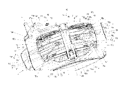
Figure 1 shows a detail of a disk brake 10 according to the invention with a
first
exemplary embodiment of a spreading device 8 according to the invention in a
schematic perspective plan view. An enlarged schematic perspective view of
the spreading device 8 according to figure 1 is illustrated in figure 2.
Figure 3
illustrates an enlarged schematic perspective view of a connection interface
20
of the spreading device 8 according to figure 1.
A brake caliper 1 engages over a brake disk 2 with a brake disk axis of
rotation
2a. The brake caliper 1 is attached, displaceably relative to the brake disk 2
ax-
ially in the direction of the brake disk axis of rotation 2a, to a brake
carrier 6, for
which purpose the brake caliper 1 is mounted on guide beams (not illustrated)
which are connected to the brake carrier 6 which is held in positionally
static
fashion on the vehicle.
The brake caliper 1 comprises an application section 11, a caliper rear
section
12 and two tension struts 13. The application section 11 runs with one side
par-
allel to the plane of the brake disk 2 on one side of the brake disk 2. The
caliper
rear section 12 is arranged on the other side of the brake disk 2, likewise so
as
to run parallel to the brake disk 2. The caliper rear section 12 is connected
to
the application section 11 at in each case one end by way of in each case one
tension strut 13. Here, the tension struts 13 run substantially at right
angles to
the application section 11 and to the caliper rear section 12.
CA 03047185 2019-06-14
- 13 -
The application section 11 has an interior space in which an application
device
(not shown) of the disk brake 10 is arranged.
In this arrangement, the application section 11, the caliper rear section 12
and
the tension struts 13 define, between them, a central opening 9 which extends
over the brake disk 2. The opening 9 has an imaginary longitudinal central
line
which lies in the plane of the brake disk 2 and which connects the imaginary
centers of the tension struts 13. Furthermore, the opening 9 has a further
imag-
inary transverse central line which connects an imaginary center of the
applica-
tion section 11 to an imaginary center of the caliper rear section 12. The
longi-
tudinal central line and the transverse central line intersect at an imaginary
cen-
ter point, which in this case is referred to as the virtual center of the
opening 9.
Brake pads 3, 3' are arranged in the brake carrier 6 in the so-called pad
slots
between the respective two brake carrier horns 17, 17'. The brake pads 3, 3'
can, during a braking operation, be pressed against the brake disk 2 at both
sides. Here, each brake pad 3, 3' has a pad carrier plate 4, 4' and, on the
side
facing toward the brake disk 2, a friction pad 5, 5' fastened to said pad
carrier
plate on a pad side 4a, which friction pad is, during the functional operation
thereof, that is to say during a braking operation, pressed against the brake
disk
2. The other side of the pad carrier plate 4, 4' will hereinafter be referred
to as
thrust side 4b.
The brake pads 3, 3' are accessible, for an exchange and for maintenance,
through the central opening 9. Said brake pads can, through said central open-
ing 9, be inserted into their associated pad slots and removed from said pad
slots again.
A run-in side ES and, opposite, a run-out side AS of the disk brake 10 are de-
fined in relation to a main direction of rotation of the brake disk 2.
A pad retaining clip 16 is arranged over the brake pads 3, 3' in a transverse
di-
rection of the opening 9 and, in the direction of the brake disk axis of
rotation
2a, between the application section 11 and the caliper rear section 12. Here,
the pad retaining clip 16 presses, by way of sections of its bottom side,
against
pad retaining springs 7, 7' of the brake pads 3, 3', whereby the latter are
held in
CA 03047185 2019-06-14
- 14 -
their pad slots. The pad retaining springs 7 are in each case held on the top
sides of the pad carrier plates 4, 4' on projections.
Braking is performed by way of the application device arranged in a receiving
space in the application section 11 of the brake caliper 1, which application
de-
vice has, for example, a brake lever which is positioned in a dome of the
brake
caliper 1. The associated brake pad 3, referred to as action-side or
application-
side brake pad, is the first to make contact with the brake disk 2 during a
brak-
ing operation. During the further course of the braking operation, reaction
forces
that occur cause the brake caliper 1 to be displaced in the opposite
direction,
driving the reaction-side brake pad 3' along until the latter likewise comes
into
frictional contact with the brake disk 2. The reaction-side brake pad 3' is
also re-
ferred to as rear-side brake pad, and will hereinafter be distinguished from
the
application-side brake pad 3 by the reference sign 3'.
After a release of the brake, the two mutually opposite brake pads 3, 3' are,
by
way of the resetting device, released from the brake disk 2 to such an extent
that said brake disk runs freely relative to the brake pads 3, 3'.
In unfavorable cases, the brake pads 3, 3' can, even after removal of the brak-
ing force, contact the brake disk 2 and thereby cause a residual rubbing
torque.
In order to prevent a residual rubbing torque, use is made of a spring
assembly
which has, on the one hand, an attachment to a positionally static component
= (for example brake carrier 6) and, on the other hand, presses the brake pads
3,
3' away from the brake disk 2 via spring action.
Such a spring assembly is provided as a so-called spreading device 8.
Here, the spreading device 8 engages in the upper region of the pad carrier
plates 4, 4' of the mutually opposite brake pads 3, 3' with equal action
counter
to the application direction. In this way, resetting forces are applied by the
spreading device 8 to the brake pads 3, 3' in their upper regions.
CA 03047185 2019-06-14
- 15 -
The spreading device 8 comprises an attachment element 18, four spring arm
units 19, 19' and two connection interfaces 20 each having a connection ele-
ment 21.
The attachment element 18 is C-shaped, fastened in a positionally static man-
ner to the brake carrier 6, specifically to brake carrier horns 17, and forms
a
holder for the spring arm units 19, 19'.
The spring arm units 19 are here formed as two identical pairs of spring arms
19a, 19'a which, by way of their one ends, are together connected via a con-
nection interface 20 to the attachment element 18 by means of a connection el-
ement 21. The other ends of in each case one spring arm unit 19 interact, as
at-
tachment sections 19b, 19'b in attachment interfaces Al, A'1, A2, A'2, with
brake pads 3, 3'. Here, spreading of the brake pads 3, 3' after a release of
the
brake is possible by way of the preload that is generated during the
application
movement.
The attachment element 18 and the spring arm units 19 here consist of a wire
material having, for example, a circular cross section.
The attachment element 18 comprises a here rectilinearly extending central
section 18a in a central region of the opening 9, approximately in a central
plane of the brake disk 2. Adjoining the central section 18a on each side is a
connection section 18b which is inclined downwardly with respect to the brake
disk 2. Thus, the attachment element 18 extends from the center of the opening
9 on both sides in each case as far as a brake carrier horn 17 of the pad slot
of
the application-side brake pad 3.
Attached to each end of the connection sections 18b is a bow-shaped connec-
tion section 18c which is bent around through approximately 90 so as to be di-
rected toward the respective brake carrier horn 17 and in each case merges in-
to a further rectilinear connection section 18d which runs toward the
respective
brake carrier horn 17. These connection sections 18d then run parallel to one
another and parallel to the brake disk axis 2a and are then bent over down-
wardly through approximately 90 into a respective fastening section 18e. Each
fastening section 18e is fastened in a bore 17a of each brake carrier horn 17
CA 03047185 2019-06-14
- 16 -
and thus realizes the positionally static retention of the attachment element
18
with the spreading device 8 on the brake carrier 6.
Here, the attachment element 18 forms a centering device for the brake caliper
1 insofar as the brake carrier 6, to which the attachment element 18 is
fastened,
forms a positionally static part relative to which the brake caliper 1 is
displacea-
bly mounted, such that, after a release of the brake and a spreading movement
of the spreading device 8, that is to say after the brake pads 3 have been
pushed apart, the brake caliper 1 is guided into a centered position.
The two spring arms 19a, 19'a of each pair of the spring units 19, 19' are
formed in mirror-image fashion with respect to the central section 18a of the
at-
tachment element 18, as can be clearly seen in figure 2.
The pairs of spring arms 19a, 19'a are arranged opposite one another in a
transverse direction of the opening 9 such that they are fastened by way of in-
ner ends, which point toward the center of the opening 9, to the attachment el-
ement 18 in each case via a connection interface 20 by means of a respective
connection element 21, wherein their outer free ends interact with the pad
carri-
er plates 4, 4' of the brake pads 3, 3'. Here, one pair of spring arms 19a,
19'a is
arranged to the right of the central point of the opening 9, wherein the other
pair
of spring arms 19a, 19'a is arranged to the left of the central point of the
open-
ing 9.
The description of one spring unit 19, 19' applies to the other spring unit
19, 19'
in mirror-image fashion, as clearly emerges from figures 1 and 2.
Each spring arm 19a, 19'a has a rectilinear body with an inner end and an
outer
end. The inner ends are close to one another and point toward the center of
the
opening 9, wherein the outer ends are far away from one another and are each
ar-
ranged over an end region of a pad carrier plate 4, 4'.
The inner ends of both spring arms 19a, 19'a are each provided with a
rectilinear
connection section 19c, 19'c. The connection sections 19c, 19'c run parallel
to
one another and parallel to a central plane of the brake disk 2, wherein they
are
connected via an upper connection bow 19d.
CA 03047185 2019-06-14
- 17 -
In this embodiment, the two spring arms 19a, 19'a are formed in one piece with
the connection bow 19d, for example as a wire bent part. However, it is also
pos-
sible that the spring arms 19a, 19'a are manufactured individually and then
sub-
sequently connected via an additional part which forms the connection bow 19d,
for example by welding. Here, it can also be possible that in this case the
connec-
tion sections 19c, 19'c and the connection bow 19d form the additional part.
The outer free end of each spring arm 19a, 19'a has a downwardly pointing at-
tachment section 19b, 19'b for respectively interacting with the pad carrier
plate 4,
4' in a respective attachment interface Al, Al, A2, A'2.
In the exemplary embodiment shown in figure 1, the attachment sections 19b,
19'b are bent over downwardly and configured rectilinearly. Here, they are re-
ceived in a form-fitting manner in receiving openings 4c, 4'c in top sides 4d,
4'd in
corner regions of the respective pad rear plate 4, 4' of the brake pads 3, 3'.
The
receiving openings 4c, 4'c communicate with the shape of the attachment
sections
19b, 19'b and are here configured as bores. The walls or the wall of a
respective
receiving opening 4c, 4'c form/forms a bearing surface for the respective
attach-
ment section 19b, 19'b. The receiving openings 4c, 4'c can take the form of
blind
holes and/or of through-holes, for example. The receiving openings 4c, 4'c can
have different cross sections, thus being, for example, round, circular, oval
or an-
gular, wherein the cross sections of the attachment sections 19b, 19'b, which
are
received in them, of the spring arms 19a, 19'a communicate with the respective
cross section of the receiving openings 4c, 4'c. However, it is also possible
that
round attachment sections 19b, 19'b can be inserted into angular or oval
receiving
openings 4c, 4'c.
If the receiving openings 4c, 4'c take the form of blind holes, the ends of
the at-
tachment sections 19b, 19'b can lie on the respective bottom of a blind hole,
which can form a bearing surface.
The inner ends of the connection sections 19c, 19'c and the connection bow
19d connecting them are connected to a respective connection element 21. The
connection elements 21 each form a connection interface 20 between the re-
CA 03047185 2019-06-14
- 18 -
spective spring units 19, 19' and the positionally static attachment element
18.
This is shown on an enlarged scale in figure 3.
The connection element 21 comprises a longitudinally extending base section
21a, two mutually opposite wing sections 21b, 21'b and two mutually opposite
pairs of sleeve sections 21c, 21'c; 21d, 21'd.
In the installed state of the spreading device 8, as shown in figure 1, the
base
section 21a extends in the longitudinal direction of the opening 9. The wing
sec-
tions 21b, 21'b are attached to an outer end of the base section 21a that
points
away from the center of the opening 9. Each wing section 21b, 21'b forms, on
each longitudinal side of the base section 21a, a lug which projects from the
base section 21a at a right angle to the longitudinal direction thereof.
At the other end, the inner end, of the base section 21a, the sleeve sections
21c, 21'c; 21d, 21'd are integrally formed on both sides, extend upwardly and
are bent around the central section 18a of the attachment element 18.
The base section 21a is adapted to the round outer shape of the central
section
18a of the attachment element 18, wherein, in the installed state, the central
section 18a is arranged so as to extend on the base section 21a in its
longitudi-
nal direction. Here, the central section 18a lies between the wing sections
21b,
21'b on a bearing section 21f of the base section 21a and within the sleeve
sec-
tions 21c, 21'c; 21d, 21'd on the base section 21a.
The associated spring unit 19, 19' is connected to the connection element 21
in
such a way that the two connection sections 21c, 21'c extend parallel to the
base section 21a of the connection element 21, below in each case a wing sec-
tion 21b, 21'b, wherein the inner ends of the two connection sections 19c,
19'c
are each upwardly bent in a 90 arc and then merge into the connection bow
19d. Here, the connection bow 19d extends between the sleeve sections 21c,
21'c; 21d, 21'd and is arranged within axial interspaces 21e, 21'e. In this
way,
the connection element 21 is connected to the spring unit 19, 19', wherein at
the same time a connection is formed with the central section 18a of the at-
tachment element 18, which extends, on the one hand, parallel to the connec-
tion sections 19c, 19'c of the spring unit 19, 19' on the base section 21a
and, on
CA 03047185 2019-06-14
- 19 -
the other hand, further through the sleeve sections 21c, 21'c; 21d, 21'd and
be-
low the connection bow 19d of the spring unit 19, 19'.
In this way, in each connection interface 20, a spring unit 19, 19' is, by way
of
the respective two spring arms 19a, 19'a, mounted on the central section 18a
of
the attachment element 18 so as to be not only axially displaceable in the
longi-
tudinal direction of the central section 18a of the attachment element 18 but
al-
so to be rotatable.
In other words, the spring units 19, 19' can move independently of one another
in the axial direction of the longitudinal axis of the central section 18a of
the at-
tachment section 18 and at the same time rotate independently of one another
about the longitudinal axis of the central section 18a. The spreading device
is
thus particularly flexible and adaptable. However, for simpler assemblability,
a
fixing of the rotatability can also be envisioned.
As a result of the increasing wear of the friction material, that is to say of
the
friction pads 5, 5' of the brake pads 3, 3' and also of the brake disk 2, the
at-
tachment of the spring arms 19a, 19'a must have a degree of freedom. This de-
gree of freedom serves to prevent multiaxial distortion/tilting of the system.
For
this purpose, the attachment of the spring elements in the form of the spring
arms 19a, 19'a by means of the connection interfaces 20 to the positionally
stat-
ic attachment element 18 is configured to be displaceable. The compensation
for the friction material wear can thus be realized by an axial sliding
movement
of the spring arm attachment in the connection interfaces 20 with respect to
the
positionally static attachment element 18.
The assembly of the complete spreading device 8 (centering unit) is designed
such that a certain play is provided at the connection interfaces 20 between
the
resilient spring units 19, 19 and the attachment element 8 (positionally
static
component). With progressive tightening of the spring units 19, 19', the
connec-
tion interfaces 20 are displaced in the direction of the center of the opening
9 of
the disk brake 10 (toward the pad retaining clip 16) as a result of this play.
The attachment of the spring units 19, 19' is effected via the respective
connec-
tion element 21. By way of example, the connection element 21 can be a corn-
CA 03047185 2019-06-14
- 20 -
pressed sheet metal element. However, it can vary in its construction. A dis-
placement in the axial direction of the wire clip is possible.
The vibrations which occur during the travel of a vehicle which has the disk
brake 10 facilitate a displacement of the connection interfaces 20, with the
re-
sult that correct functioning can also be assumed in the case of
contamination.
Figures 4-6 show further schematic perspective illustrations of the spreading
device 8 according to figure 1 with a first variant of the connection
interface 20.
Figure 7 illustrates an enlarged schematic perspective view of the variant of
the
connection interface 20 of the spreading device 8 according to figures 4-6.
The first variant of the connection interface 20 consists in a downwardly bent-
over spacer section 22 being attached to the outer end of the connection ele-
ment 21. The connection sections 19c, 19'c of the spring units 19, 19' bear
against lateral sections 22a of the spacer section 22.
The associated connection element 21 is shown in figure 7.
Figures 8-9 illustrate enlarged schematic perspective partial illustrations of
the
spreading device 8 according to figure 1 with a second variant of the
connection
interface 20 with a slightly modified connection element 21. Here, the spacer
sec-
tion 22 is provided with a central recess 22a, as can clearly be seen in
figure 10
in an enlarged schematic perspective view of the second variant of the
connection
interface 20 of the spreading device 21 according to figures 8-9.
Figure 11 shows an enlarged schematic perspective partial illustration of the
spreading device according to figure 1 with a third variant of the connection
in-
terface 20. The associated connection element 23, which is here reduced in its
form, is shown in figure 12 in an enlarged schematic perspective view of the
third variant of the connection interface 20 of the spreading device 8
according
to figure 11.
Figures 13 and 14 illustrate enlarged schematic perspective partial
illustrations
of the spreading device 8 according to figure 1 with a fourth variant of the
con-
nection interface 20 with a connection element 24. Here, four wing sections
CA 03047185 2019-06-14
- 21 -24b, 24'b; 24d, 24'd are provided, wherein a guide section is provided
as a fork
guide 24f, 24'f with a pin 25 for securing.
Figures 15-16 show enlarged schematic perspective views of a first variant of
the spreading device 8 according to figure 1 with a fifth variant of the
connection
interface 8. Figure 17 shows an enlarged schematic perspective view of a
spring arm unit 19 of the first variant of the spreading device 8 according to
fig-
ures 15-16.
In this variant, guide elements 26 with pins 26a are received in bow sections
19e, 19'e of the spring units. Here, the connection sections 19c, 19'c are
each
provided as supporting sections 27 with bow sections 27a, 27'a in a horizontal
plane. The central section 18a of the attachment element 18 is arranged here
on the supporting sections 27 and is held by the pins 26a of the guide
elements
26 on the supporting sections 27.
Figure 18 shows an enlarged schematic partial perspective view of a second
variant of the spreading device 8 according to figure 1 with a sixth variant
of the
connection interface 20 with a connection element 26. The connection element
26 is structurally similar to that of the fifth variant, but, unlike the
latter, is ar-
ranged below the central section 18a of the attachment element 18. Here, the
central section 18a runs on the pin 26a of the guide element 26 and extends
through the connection bow 19d of the spring unit 19, 19'.
Figure 19 shows an enlarged schematic partial perspective view of a third vari-
ant of the spreading device 8 according to figure 1 with a seventh variant of
the
connection interface 20. Figure 20 shows an enlarged perspective view of the
seventh variant of the connection interface 20 of the third variant of the
spread-
ing device according to figure 19. Here, a connection element 28 is formed as
a
guide section by windings 28a of the connection sections 19c, 19'c around the
central section 18a of the attachment element 18. The connection element 28 is
here formed in the manner of a coil.
In this way, in this seventh variant, the spring arms 19a, 19'a are formed in
one
piece together with the connection element 28. In other words, the connection
element 28 of the connection interface 20 is formed in one piece with the
spring
CA 03047185 2019-06-14
- 22 -
arms 19a, 19'a. Here, too, it is conceivable for the spring arms 19a, 19'a to
be
produced separately, wherein the connection element 28 is subsequently con-
nected as an additional part to the spring arms 19a, 19'a, for example by weld-
ing.
Figures 21-22 illustrate details of the disk brake 10 according to the
invention
with the spreading device 8 according to the invention according to figure 1
with
an eighth variant of the connection interface 20.
The connection interfaces 20 here have two connection elements 29 which are
connected by a common base section 29a. The connection element 29 is best
shown in figure 28 and has the already above-described wing sections 29b,
29'b and sleeve sections 29c, 29'c; 29d, 29'd with interspaces 29e, 29'e. In
ad-
dition, still further wing sections 29f, 29'f are attached to the base section
29a
between the sleeve sections 29c, 29'c; 29d, 29'd and a connection region of
the
base section 29a. Unlike the connection interface 20 according to figure 1,
the
connection bow is arranged not in the sleeve sections 29c, 29'c; 29d, 29'd but
over the ends of guide sections 29g, 29'g. The connection region of the base
section 29a is provided with the longitudinally extending, upwardly bent-over
guide sections 29g, 29'g. The central section 18a of the attachment element 18
lies on the connection region of the base section 29a between the two lateral
sections 29g, 29g.
The attachment interfaces Al, A'1, A2, A'2 are configured with receiving open-
ings 4c, 4'c as in the exemplary embodiment according to figure 1, but, by con-
trast thereto, are offset further toward the center on the top side 4d, 4'd of
the
respective pad rear plate 4, 4'.
Figures 23-24 show the disk brake 10 according to the invention according to
figures 21-22 with a first variant of attachment interfaces Al, Al, A2, A'2.
Here, the receiving openings 4c, 4'c are formed as milled or cast elongated
holes. These elongated holes can take the form of blind holes and/or of
through-holes.
Figure 25 illustrates the disk brake 10 according to the invention according
to
figures 21-22 with a second variant of attachment interfaces Al, A'1, A2, A'2,
CA 03047185 2019-06-14
- 23 -
wherein the attachment sections 19b, 19'b of the spring arms 19a, 19'a are at-
tached to connection sections 19g, 19'g configured as extensions and in bores
which are incorporated, for example, in a sprue 30, 30' in the center of the
fric-
tion radius on the thrust sides 4b, 4'b of the pad rear plates 4, 4'. Tilting
of the
brake pads 3, 3' is thereby counteracted.
The connection sections 19g, 19'g are in turn connected by their upper ends to
the associated spring arm 19a, 19'a via in each case a further connection sec-
tion 19f, 19'f. Here, the connection sections 19g, 19'g extend parallel to the
re-
spective thrust side 4b, 4'b of the pad carrier plate 4, 4', wherein the
connection
sections 19f, 19'f are attached at approximately a right angle to the upper
ends
of the connection sections 19g, 19'g and extend parallel to the brake disk
axis
of rotation 2a over a section of the top side 4d, 4'd of the respective pad
carrier
plate 4, 4' and can lie on this section of the top side 4d, 4'd.
Figures 26-27 show the disk brake 10 according to the invention according to
figures 21-22 with a third variant of attachment interfaces Al, A'l , A2, A'2.
The
spring arms 19a, 19'a bear laterally by way of their attachment sections 19b,
19'b against a cylinder pin 31 in the pad rear plate 4, 4'. The cylinder pins
31
are inserted into fitting bores and optionally have a shoulder 32. The
shoulder
32 serves to prevent a relative movement between the stainless steel of the at-
tachment sections 19b, 19'b and the cast material of the pad rear plate 4, 4'.
Figure 28 shows the disk brake 10 according to the invention according to fig-
ures 21-22 with a third variant of attachment interfaces Al, A'1, A2, A'2. In
this
third variant, the attachment interfaces Al, A'l , A2, A'2 each comprise a
guide
element 33 with guide sections 33a. The guide sections 33a extend parallel to
one another in the longitudinal direction of the pad rear plate 4, 4' and
define a
guide receptacle 33b between them. The attachment sections 19b, 19'b of the
spring arms 19a, 19'a are in engagement with the respective guide receptacle
33b. The guide element 33 is pressed into the pad rear plate 4, 4' for
example,
can, for example, be produced from stainless steel and prevents a relative
movement between the hard spring material of the attachment sections 19b,
19'b and the soft cast material of the pad rear plate 4, 4'.
CA 03047185 2019-06-14
- 24 -
Figure 29 illustrates the disk brake 10 according to the invention according
to
figures 21-22 with a fourth variant of attachment interfaces.
The attachment sections 19b, 19'b of the spring arms 19a, 19'a are pressed
flat
at the end to form flat end sections 34 in order that an elongated hole 34a
can
then be punched out. Said elongated hole 34 can be placed over a cylinder pin
31, for example.
Figure 30 shows the disk brake 10 according to the invention according to fig-
ures 21-22 with a fifth variant of attachment interfaces Al , A'l , A2, A'2.
The at-
tachment sections 19b, 19'b of the spring arms 19a, 19'a are guided on a cor-
ner section 35 of the pad rear plate 4, 4' on a milled shoulder 35a. The
shoulder
35a has a thrust surface 35b and a bearing surface 35c. The thrust surface 35b
is here parallel to the pad side 4b, 4'b of the pad rear plate 4, 4'. The
attach-
ment sections 19b, 19'b are in contact with the thrust surface 35b and the
bear-
ing surface 35c.
Figure 31 illustrates the disk brake 10 according to the invention according
to
figures 21-22 with a sixth variant of attachment interfaces Al, Al, A2, A'2.
A guide element consisting, for example, of stainless steel is fitted over the
milled shoulder 35 in the pad rear plate 4, 4' and, where appropriate, welded
or
adhesively bonded. The attachment sections 19b, 19'b of the spring arms 19a,
19'a can be guided over this additional component.
Figure 32 shows the disk brake 10 according to the invention according to fig-
ures 21-22 with a seventh variant of attachment interfaces Al, Al, A2, A'2. In
this variant, the attachment sections 19b, 19'b of the spring arms 19a, 19'a
are
in engagement with in each case a spring end 7a, 7'a of the pad retaining
springs 7, 7' in elongated holes 7b.
Figure 33 illustrates the disk brake 10 according to the invention according
to
figure 23 with a ninth variant of the connection interface 20 with a
connection
element 37. Figure 34 shows an enlarged schematic perspective illustration of
the ninth variant of the connection interface 20 with the connection element
37
according to figure 33.
CA 03047185 2019-06-14
- 25 -
In the ninth variant, the connection element 37 has sleeve sections 37a, 37'a;
37b, 37'b with an interspace 37c and a leadthrough opening 37d. The ends of
the connection sections 19c, 19'c of the spring unit 19, 19' and their
connection
bow 19d is press-fitted with the sleeve sections 37a, 37'a; 37b, 37'b on both
sides. The central section 18a of the attachment element 18 extends through
the leadthrough opening 37d of the sleeve sections 37a, 37'a; 37b, 37'b.
Figures 35-36 show schematic partial views of the disk brake 10 according to
the invention according to figures 26-27 with a fourth variant of the
spreading
device 8 and the eighth variant of the connection interface 20 according to
fig-
ure 28.
The connection interface 20 here has a connection element 38 which is struc-
turally similar to the connection element 29 (see for example figure 28).
The spring arm pairs of the spring units 19, 19' do not engage over the brake
disk 2 here but are each arranged on one side of the brake disk.
Illustrated here is an attachment possibility for two spring arms 19a, 19'a
which
in one case are present continuously on the application side and in one case
are present continuously on the caliper rear side. The spring arms 19a, 19'a
are
connected via extended connection sections 19c, 19'c. The extended connec-
tion sections 19c, 19'c extend parallel to and next to guide sections 38g,
38'g of
the connection element 38.
Figures 37 and 38 illustrate enlarged schematic perspective partial
illustrations
of the spreading device 8 according to figure 1 with a tenth variant of the
con-
nection interface 20. Figure 39 shows an enlarged schematic perspective view
of the tenth variant of the connection interface of the spreading device 8 ac-
cording to figures 37-38 with a connection element 39.
The tenth variant of the connection interface 20 differs from the first
variant of
the connection interface 20 according to figures 5, 6 and 7 in a varied connec-
tion element 39, wherein only some sections are formed differently, as will be
explained below.
CA 03047185 2019-06-14
- 26 -
The connection element 39 comprises, like the connection element 21, a longi-
tudinally extending base section 39a with a bearing section 39f, two mutually
opposite wing sections 39b, 39'b and two mutually opposite pairs of sleeve sec-
tions 39c, 39'c; 39d, 39'd.
By contrast with the connection element 21, the two wing sections 39b, 39'b
are
formed convexly with in each case a downwardly pointing edge section 39g,
39'g, wherein rounded contact sections 39h, 39'h formed from the convex wing
sections 39b, 39'b are arranged on the bottom sides of the convex wing sec-
tions 39b, 39'b. The wing sections 39b, 39'b with their contact sections 39h,
39'h correspond in their rounded shape to the outer shape of the connection
sections 19c, 19'c of the spring arms 19a, 19'a.
The base section 39a is adapted to the round outer shape of the central
section
18a of the attachment element 18, wherein, in the installed state, the central
section 18a is arranged so as to extend on the base section 39a in its
longitudi-
nal direction. Here, the central section 18a lies between the wing sections
39b,
39'b on the bearing section 39f of the base section 39a and within the sleeve
sections 39c, 39'c; 39d, 39'd on the base section 39a, as in the case of the
connection element 21.
The associated spring unit 19, 19' is here, too, connected to the connection
el-
ement 39 in such a way that the two connection sections 39c, 39'c extend par-
allel to the base section 39a of the connection element 39, below in each case
a wing section 39b, 39'b, wherein the inner ends of the two connection
sections
19c, 19'c are each upwardly bent in a 900 arc and then merge into the connec-
tion bow 19d. Here, the connection bow 19d extends between the sleeve sec-
tions 39c, 39'c; 39d, 39'd and is arranged within axial interspaces 39e, 39'e,
which can also be referred to as gaps.
The spring arm unit 19, 19' extends through said gap and is thus supported in
the gap, with the result that sliding out is avoided during a displacement in
the
longitudinal direction of the central section 18a of the attachment element
18.
CA 03047185 2019-06-14
- 27 -
In this way, the connection element 39 is connected to the spring unit 19,
19',
wherein at the same time a connection is formed with the central section 18a
of
the attachment element 18, which extends, on the one hand, parallel to the
connection sections 19c, 19'c of the spring unit 19, 19' on the base section
39a
and, on the other hand, further through the sleeve sections 39c, 39'c; 39d,
39'd
and below the connection bow 19d of the spring unit 19, 19'.
The connection element 39 also has the spacer section 22 as a lug which is in-
clined downwardly in the longitudinal direction of the base section 39a and of
which the lateral sections 22a are in contact with in each case a spring arm
19a, 19'a. In this variant, too, the connection sections 19c, 19'c of the
spring
units 19, 19' bear against the lateral sections 22a of the spacer section 22.
In
operation, the spacer section 22 ensures a lateral support for the two spring
arms in the inward direction, that is to say pointing in each case toward the
spacer section 22, and thus defines a bearing point for the spring arms 19a,
19'a.
By contrast with the connection element 21 of the first variant of the
connection
interface 20 according to figures 5, 6 and 7, the two wing sections 39b, 39'b,
which can also be referred to as wing lugs, are inclined downwardly in a bow
shape and safeguard, on the one hand, against a downwardly directed tilting of
the spring arms 19a, 19'a and, on the other hand, against the spring arms 19a,
19'a sliding out upwardly.
During mounting, the spring arm unit 19, 19' is threaded in under the sleeve
sections 39c, 39'c; 39d, 39'd and clipped into the two laterally downwardly
pro-
jecting wing sections 39b, 39'b, which are formed in the manner of lugs.
The pad retaining springs 7, 7' are provided at each of their ends with a
bevel.
These bevels each point toward the brake disk 2 and serve to facilitate mount-
ing and demounting of the spreading device 8, wherein the spring arms 19a,
19'a can be prevented from hooking on the ends of the pad retaining springs 7,
7' that point toward the brake disk 2. These bevels are not designated, but
are
clearly evident in figures 1, 21-31, 33, 35-36.
CA 03047185 2019-06-14
- 28 -
Figure 40 shows a schematic perspective view of a brake carrier horn 17, 17'
with a receiving opening 17a and a plug 40. Figure 41 shows a schematic sec-
tional view of the brake carrier horn 17, 17' with inserted plug 40 according
to
figure 40. Figure 42 illustrates an enlarged schematic perspective view of the
plug 40 according to figures 40 and 41.
The plug 40 serves for closing the receiving openings 17a if the disk brake 1
is
intended for subsequent retrofitting with a spreading device 8. In such a
case,
the brake carrier 6 with the brake carrier horns 17, 17' each having a
receiving
opening 17a can be already installed, wherein the unused receiving openings
17a are closed by a respective plug 40 and thus protected against contamina-
tion. The plug 40 can also be used for temporary protection of the receiving
openings 17a in the case of maintenance and replacement of the spreading de-
vice 8.
The plug 40 has a body 41 and a handle 42. The body 41 is designed to be
conical with an upper handle section 41a and a lower end section 41b, wherein
the body 41 tapers in its longitudinal direction from the handle section 41a
to
the end section 41b. The body 41 additionally has peripheral beads 41c be-
tween which peripheral recesses 41d are arranged. The beads 41c and the re-
cesses 41d are successively arranged, coaxially to a longitudinal axis of the
body 41, on said body in its longitudinal direction.
The handle 42 is mounted on the handle section 41a of the body 41. The han-
dle 42 has a parallelepipedal shape and is provided at its upper free end with
bead-form edges for easier handling. A length of the handle 42 corresponds
approximately to a length of the body 41 in the longitudinal direction.
An average diameter of the body 41 corresponds to the inside diameter of the
receiving openings 17a.
One material of the plug 40 is a heat-resistant plastic. The plug 40 can also
have a metal core which is overmolded with a plastic which forms the beads
41c. The beads 41c are substantially elastic.
CA 03047185 2019-06-14
- 29 -
As shown in figure 41, the plug 40 is inserted, with its lower end 41b
leading, in-
to the receiving opening 17a into the brake carrier horn 17, 17'. Here, the
body
41 has approximately three quarters of its length received in the receiving
open-
ing 17a. The elastic beads 17 are here compressed, are in contact with an
inner
wall 43 of the receiving opening 17a and thus seal the receiving opening 17a
with respect to the surroundings.
The receiving openings 17a here take the form of blind holes and have bevels
44 on their top side for easier threading in of the fastening sections 18e of
the
attachment element 18, as for the plug 40. The receiving openings 17a can also
be through-holes, in which case a further plug 40 is provided in each case.
The receiving openings 4c, 4'c of the attachment interfaces Al, A'1; A2, A'2
take the form of through-holes and/or blind holes, as already described above.
In both cases, the receiving openings 4c, 4'c allow a stable seat for the
attach-
ment sections 19b, 19'b.
The receiving openings 4c, 4'c of the attachment interfaces Al, A'1; A2, A'2
can
extend, for example, over one quarter, one third, two quarters, two thirds,
three
thirds or more, or over the entire lateral length (as through-hole) of a brake
pad
3, 3'. Here, the lengths of the attachment sections 19b, 19'b can correspond
to
the lengths of the receiving openings 4c, 4'c. In this way, an introduction of
force of the spreading device 8 to the brake pads 3, 3' for resetting is
exerted
which can thus extend beyond the whole side of the brake pads 3, 3'.
In the case that the receiving openings 4c, 4'c of the attachment interfaces
Al,
Al; A2, A'2 take the form of blind holes, the attachment sections 19b, 19'b
can
bear with their ends in contact with the respective blind hole bottom, wherein
the attachment sections 19b, 19'b can then have their peripheral surfaces in
contact with the respective inner wall of the associated receiving opening 4c,
4'c.
It is furthermore conceivable that the attachment sections 19b, 19'b are
provid-
ed with sleeves, wherein these sleeves are each pushed onto an attachment
section 19b, 19'b. This is not illustrated, but can be easily envisioned. Such
CA 03047185 2019-06-14
- 30 -
sleeves can of course also be pushed onto the fastening sections 18e of the at-
tachment element 18.
The invention is not restricted by the exemplary embodiments described above.
It
may be modified within the scope of the appended claims.
CA 03047185 2019-06-14
- 31 -
LIST OF REFERENCE SIGNS
1 Brake caliper
2 Brake disk
2a Brake disk axis of rotation
3, 3' Brake pad
4, 4' Pad carrier plate
4a Pad side
4b, 4'b Thrust side
4c, 4'c Receiving opening
4d, 4'd Top side
5, 5' Friction pad
6 Brake carrier
7, 7' Pad retaining spring
7a Spring end
7b Elongated hole
8 Spreading device
9 Opening
10 Disk brake
11 Application section
12 Caliper rear section
13 Tension strut
14, 15 Retaining section
16 Pad retaining clip
17, 17' Brake carrier horn
17a Receiving opening
18 Attachment element
18a Central section
18b, 18c, 18d Connection section
18e Fastening section
19, 19' Spring arm unit
19a, 19'a Spring arm
19b, 19'b Attachment section
19c, 19'c Connection section
19d Connection bow
19e, 19'e Bow section
CA 03047185 2019-06-14
- 32 -
19f, 191; 19g, 19'g Connection section
20 Connection interlace
21 Connection element
21a Base section
21b, 21'bWing section
21c, 21'c; 21d, 21'd Sleeve section
21e, 21'e Interspace
21f Bearing section
22 Spacer section
22a, 22'a Lateral section
22b Recess
23 Connection element
23a Base section
23b, 23'b Wing section
23c Bearing section
24 Connection element
24a Base section
24b, 24b; 24d, 24'd Wing section
24c, 24'c; 24e, 24'e Guide section
24f, 24'f Fork guide
Pin
26 Guide element
26a Pin
26b, 26'b Disk section
25 27 Supporting section
27a, 27'a Bow section
28 Connection element
28a Winding
29 Connection element
29a Base section
29b, 29'b Wing section
29c, 29'c; 29d, 29'd Sleeve section
29e, 29'e Interspace
29f, 29'f Wing section
29g, 29'g Guide section
30, 30' Retaining projection
CA 03047185 2019-06-14
- 33 -
31, 31 Cylinder pin
32, 32' Shoulder
33 Guide element
33a Guide section
33b Guide receptacle
34 End section
34a Elongated hole
35 Corner section
35a Shoulder
35b Thrust surface
35c Bearing surface
36 Guide element
36a Base section
36b, 36c Wall section
36d Bearing section
37 Connection element
37a, 37'a; 37b, 37'b Sleeve section
37c lnterspace
37d Leadthrough opening
38 Connection element
38a Base section
38b, 38'b Wing section
38c, 38'c; 38d, 38'd Sleeve section
38e, 38'e Interspace
38f, 38'f Wing section
38g, 38'g Guide section
39 Connection element
39a Base section
39b, 39'b Wing section
39c, 39'c; 39d, 39'd Sleeve section
39e, 39'e lnterspace
39f Bearing section
39g, 39'g Edge section
39h, 39'h Contact surface
40 Plug
41 Body
CA 03047185 2019-06-14
- 34 -
41a Handle section
41b End section
41c Bead
41d Recess
42 Handle
43 Inner wall
44 Bevel
Al, Al , A2, A2 Attachment interface
AS Run-out side
ES Run-in side