Note : Les descriptions sont présentées dans la langue officielle dans laquelle elles ont été soumises.
CALIBRATION APPARATUS AND METHODS
FOR CALIBRATING A MEDICAL INSTRUMENT
CROSS-REFERENCE TO RELATED APPLICATION(S)
[0001] This document is a utility application claiming the benefit of, and
priority to: US Design
Application No. 29/588647 filed on December 22, 2016, entitled "CALIBRATION
APPARATUS".
TECHNICAL FIELD
[0002] The present disclosure is generally technically related to image guided
medical procedures.
More particularly, the present disclosure is generally technically related to
a calibration apparatus
for a medical tool. Even more particularly, the present disclosure is
generally technically related
to a calibration apparatus for a medical tool used in image guided medical
procedures.
BACKGROUND
[0003] The related art generally involves image guided medical procedures
using a surgical
instrument, such as a fiber optic scope, an optical coherence tomography (OCT)
probe, a micro
ultrasound transducer, an electronic sensor or stimulator, or an access port-
based surgery. In the
example of a port-based surgery, a surgeon or robotic surgical system may
perform a surgical
procedure involving tumor resection in which the residual tumor remaining
after is minimized,
while also minimizing trauma to the intact white and grey matter of the brain.
In such procedures,
trauma may occur, for example, due to contact with the access port, stress to
the brain matter,
unintentional impact with surgical devices, and/or accidental resection of
healthy tissue. A key to
minimizing trauma is ensuring that the spatial reference of the patient and
the medical tools used
in the procedure as understood by the surgical system is as accurate as
possible.
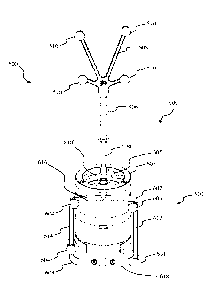
[0005] FIG. 1 illustrates the insertion of an access port into a human brain,
for providing access to
internal brain tissue during a medical procedure, in accordance with the
related art. In FIG. 1,
1
Date Recue/Date Received 2022-08-15
CA 03048160 2019-06-21
WO 2018/115983 PCT/IB2017/051604
an access port 12 is inserted into a human brain 10, providing access to
internal brain tissue. The
access port 12 may include such instruments as catheters, surgical probes, or
cylindrical ports,
such as the NICO BrainPath . Surgical tools and instruments may then be
inserted within the
lumen of the access port in order to perform surgical, diagnostic, or
therapeutic procedures, such
as resecting tumors, as necessary. The present disclosure applies equally well
to catheters, deep
brain stimulation (DBS) needles, a biopsy procedure, and also to biopsies
and/or catheters in
other medical procedures performed on other parts of the body.
[0006] In the example of a port-based surgery, a straight or linear access
port 12 is typically
guided down a sulci path of the brain. Surgical instruments would then be
inserted down the
access port 12. Optical tracking systems, used in a medical procedure, track
the position of a
part of the instrument that is within the line-of-site of the optical tracking
camera. These optical
tracking systems require a knowledge of the dimensions of the instrument being
tracked so that,
for example, the optical tracking system knows the position in space of a tip
of a medical
instrument relative to the tracking markers being tracked.
[0008] Conventional systems have shortcomings with respect to establishing and
maintaining the
reference between the tracking markers located on a medical instrument and the
point of interest
on the instrument relative to those tracking markers for reasons, such as
instruments bending or
deforming over time. Additionally, the related art calibration devices face
challenges in relation
to tools having a variety of cross-sectional shapes and cross-sectional areas,
e.g., having various
diameters. Also, the related art calibration devices use software that is
challenged by tools of
various sizes. Therefore, a need exists for an improved calibration of optical
tracking systems
with respect to the various medical instruments that those tracking systems
must track.
2
CA 03048160 2019-06-21
WO 2018/115983 PCT/IB2017/051604
SUMMARY
[0009] To address at least the challenges experienced in the related art, in
an embodiment of the
present disclosure, a calibration apparatus for calibrating a medical tool
having a tool tracking
marker is provided. The medical tool and the calibration apparatus are for use
with a medical
navigation system. The calibration apparatus comprises a frame, a frame
tracking marker
attached to the frame, and a reference point feature formed on the frame or
the body. The
reference point feature provides a known spatial reference point relative to
the frame tracking
marker.
[0010] In addition, the calibration apparatus increases accuracy of an entire
navigation system,
such as an image-guided navigation system, in accordance with embodiments of
the present
disclosure. By calibrating a tracked tool via the calibration apparatus, at
least the following
solutions are provided: (a) the navigation system is adaptable for using tools
having higher
tolerances than those in the related art, whereby the calibration apparatus is
configured to correct
for variations from a nominal variation to a large variation (relative to
calibration devices in the
related art), and whereby tool fabrication costs are decreased, (b) a tracked
tool is configurable
by an end user, e.g., by configuring a suction tool in relation to a plurality
of possible tool tip
locations, and (c) a tracked tool is configurable, regardless of tip geometry,
e.g., providing a
solution for both a pointed tool tip which seat well in relation to a bottom
portion of a conical
divot and for a cylindrical tool tip (such as for a suction tool) which may,
otherwise, seat at a
location above a bottom portion of a conical divot and may not be centered
when seated.
[0000] In relation to the foregoing solution (c), related art challenges are
addressed by the
calibration apparatus of the present disclosure via a feature for abutting all
tips against a flat
surface while using a feature for centering the axis of the tool in a known
position, whereby any
tool, regardless of diameter, cross-sectional area, cross-sectional shape, or
other tip geometry,
seats in the calibration apparatus in the same manner. Also, the calibration
apparatus increases
accuracy of an entire navigation system, such as a non-image-guided navigation
system, in
accordance with embodiments of the present disclosure. For a non-image-guided
navigation
system, the calibration apparatus is configured for use with the Synaptive
Drive system,
3
CA 03048160 2019-06-21
WO 2018/115983 PCT/IB2017/051604
wherein the foregoing solution (b) is applicable, and wherein calibration
information is used to
align an optical payload.
[0011] In embodiments of the present disclosure, a frame tracking marker
comprises at least one
of a passive reflective tracking marker, such as at least one of a passive
reflective tracking sphere
and a passive reflective tracking disk, an active infrared (IR) marker, an
active light emitting
diode (LED), and a graphical pattern. The frame may have at least three
tracking markers
attached to a same side of the frame.
[0012] In an embodiment of the present disclosure, a medical navigation system
comprises a
medical tool, a calibration apparatus, and a controller. The medical tool has
a tool tracking
marker. The calibration apparatus is configured to calibrate the medical tool
and comprises a
frame, a frame tracking marker attached to the frame, and a reference point
feature disposed in
relation to the frame. The reference point feature provides a known spatial
reference point
relative to the frame tracking marker. The medical navigation system further
comprises a sensor
coupled with the controller for detecting the tracking markers, e.g., the
frame tracking markers.
The sensor provides a signal to the controller to indicate the positions of
the tracking markers in
space. The reference point feature may include a divot whereby the tip of the
medical tool
(which has at least three tracking markers attached thereto) is insertable
into the divot to abut
against the floor of the divot for calibrating and verifying the medical tool
dimensions by the
medical navigation system.
[0013] In an embodiment of the present disclosure, a method of verifying
dimensions of a
medical tool having an attached tool tracking marker comprises using a
calibration apparatus
having a frame, a frame tracking marker attached to the frame, and a reference
point feature
disposed in relation to the frame. The reference point feature provides a
known spatial reference
point relative to the frame tracking marker. The method further comprises:
detecting the tool
tracking marker and the frame tracking marker; calculating the expected
spatial relationship of
the tool tracking marker relative to the frame tracking marker; and re-
registering the tool when
the dimensions of the medical tool have changed beyond a given, predetermined,
defined, or
predefined threshold.
4
CA 03048160 2019-06-21
WO 2018/115983 PCT/IB2017/051604
[0014] In an embodiment of the present disclosure, a calibration apparatus,
operable with a
medical navigation system, for calibrating a medical tool having a tip,
comprises: a calibration
body configured to accommodate a plurality of tool dimensions and having a
plurality of
cooperating spring-loaded cams for accommodating a plurality of tool cross-
sectional
dimensions; a frame configured to couple with the calibration body and having
at least one frame
tracking marker coupled therewith; and a reference point feature coupled with
the calibration
body, the reference point feature providing a known spatial reference point
relative to the at least
one frame tracking marker.
[0015] In an embodiment of the present disclosure, a method of fabricating a
calibration
apparatus, operable with a medical navigation system, for calibrating a
medical tool having a tip,
comprises: providing a calibration body configured to accommodate a plurality
of tool
dimensions and having a plurality of cooperating spring-loaded cams for
accommodating a
plurality of tool cross-sectional dimensions; providing a frame configured to
couple with the
calibration body and having at least one frame tracking marker coupled
therewith; and providing
a reference point feature coupled with the body, the reference point feature
providing a known
spatial reference point relative to the at least one frame tracking marker.
[0016] In an embodiment of the present disclosure, a method of calibrating a
medical tool,
having a tip, by way of a calibration apparatus, operable with a medical
navigation system,
comprises: providing the calibration apparatus comprising: providing a
calibration body
configured to accommodate a plurality of tool dimensions and having a
plurality of cooperating
spring-loaded cams for accommodating a plurality of tool cross-sectional
dimensions; providing
a frame configured to couple with the calibration body and having at least one
frame tracking
marker coupled therewith; and providing a reference point feature coupled with
the calibration
body, the reference point feature providing a known spatial reference point
relative to the at least
one frame tracking marker; detecting the at least one tool tracking marker and
the at least one
frame tracking marker; calculating the expected spatial relationship of the at
least one tool
tracking marker relative to the at least one frame tracking marker; and re-
calibrating the tool if at
least one tool dimension if the medical tool is altered beyond a threshold
value in relation to the
expected spatial relationship. The method of calibrating further comprises
verifying a tool,
wherein verifying the tool comprises abutting a tip of the tool against a
floor of a divot.
CA 03048160 2019-06-21
WO 2018/115983 PCT/IB2017/051604
[0017] A further understanding of the functional and structural features as
well as aspects of the
present disclosure is provided by the following Detailed Description and the
Drawing.
BRIEF DESCRIPTION OF THE DRAWING
[0018] The above, and other, aspects and features of several embodiments of
the present
disclosure will be more apparent from the following Detailed Description as
presented in
conjunction with the following several figures of the Drawing.
[0019] FIG. 1 is a diagram illustrating, in a side view, the insertion of an
access port into a
human brain, for providing access to internal brain tissue during a medical
procedure, in
accordance with the related art.
[0020] FIG. 2 is a diagram illustrating, in a perspective view, a surgical
environment, such as an
operating room, wherein an exemplary navigation system to support minimally
invasive surgery
may be implemented, in accordance with an embodiment of the invention.
[0021] FIG. 3 is a block diagram illustrating a control and processing system
useable in the
navigation system, as shown in FIG. 2, in accordance with an embodiment of the
invention.
[0022] FIG. 4A is a flow diagram illustrating a method of using the navigation
system, as shown
in FIG. 2, for a surgical procedure, in accordance with an embodiment of the
invention.
[0023] FIG. 4B is a flow diagram illustrating alternative steps of registering
a patient for a
surgical procedure, in the method of using the navigation system, as shown in
FIG. 4A, in
accordance with an embodiment of the invention.
[0024] FIG. 5 is a diagram illustrating, in a perspective view, an exemplary
tracked instrument
with which embodiments of the present disclosure may be implemented.
[0025] FIG. 6 is a diagram illustrating, in a frontal perspective view, the
tracked instrument, as
shown in FIG. 5, inserted into a calibration apparatus, in accordance with an
embodiment of the
invention.
6
CA 03048160 2019-06-21
WO 2018/115983 PCT/IB2017/051604
[0026] FIG. 7 is a diagram illustrating, in a frontal perspective view, the
calibration apparatus, as
shown in FIG. 6, in accordance with an embodiment of the invention.
[0027] FIG. 8 is a diagram illustrating, in a front view, the calibration
apparatus, as shown in
FIG. 7, in accordance with an embodiment of the invention.
[0028] FIG. 9 is a diagram illustrating, in a rear view, the calibration
apparatus, as shown in FIG.
7, in accordance with an embodiment of the invention.
[0029] FIG. 10 is a diagram illustrating, in a side view, the calibration
apparatus, as shown in
FIG. 7, in accordance with an embodiment of the invention.
[0030] FIG. 11 is a diagram illustrating, in an opposing side view, the
calibration apparatus, as
shown in FIG. 7, in accordance with an embodiment of the invention.
[0031] FIG. 12 is a diagram illustrating, in a top view, the calibration
apparatus, as shown in
FIG. 7, in accordance with an embodiment of the invention.
[0032] FIG. 13 is a diagram illustrating, in a bottom view, the calibration
apparatus, as shown in
FIG. 7, in accordance with an embodiment of the invention.
[0033] FIG. 14 is a flow diagram illustrating a method of verifying and re-
registering a medical
tool, in accordance with an embodiment of the invention.
[0034] FIG. 15A is a diagram illustrating, in a cutaway perspective view, a
calibration body, as
included in a calibration apparatus, operable with a medical navigation
system, for calibrating a
medical device having a tip, in accordance with an embodiment of the present
disclosure.
[0035] FIG. 15B is a diagram illustrating, in an alternate cutaway perspective
view, a calibration
body, as included in a calibration apparatus and shown in FIG. 15A, operable
with a medical
navigation system, for calibrating a medical device having a tip, in
accordance with an
embodiment of the present disclosure.
7
CA 03048160 2019-06-21
WO 2018/115983 PCT/IB2017/051604
[0036] FIG. 15C is a diagram illustrating, in a perspective view of a
calibration body, as included
in a calibration apparatus and shown in FIG. 15A, operable with a medical
navigation system, for
calibrating a medical device having a tip, in accordance with an embodiment of
the present
disclosure.
[0037] FIG. 16A is a diagram illustrating, in a perspective view, a
calibration body, as included
in a calibration apparatus, operable with a medical navigation system, for
calibrating a medical
device having a tip, in accordance with an embodiment of the present
disclosure.
[0038] FIG. 16B is a diagram illustrating, in a cutaway perspective view, a
calibration body, as
included in a calibration apparatus and shown in FIG. 16A, operable with a
medical navigation
system, for calibrating a medical device having a tip, in accordance with an
embodiment of the
present disclosure.
[0039] FIG. 17A is a diagram illustrating, in a perspective view, a
calibration body, as included
in a calibration apparatus, operable with a medical navigation system, for
calibrating a medical
device having a tip, in accordance with an embodiment of the present
disclosure.
[0040] FIG. 17B is a diagram illustrating, in a cutaway top perspective view,
a calibration body,
as included in a calibration apparatus and shown in FIG. 17A, operable with a
medical
navigation system, for calibrating a medical device having a tip, in
accordance with an
embodiment of the present disclosure.
[0041] FIG. 18 is a diagram illustrating, in a frontal perspective view, a
calibration apparatus,
operable with a medical navigation system, for calibrating a medical device
having a tip, such as
a tracked instrument, wherein the medical tool is inserted into the
calibration apparatus, in
accordance with an embodiment of the present disclosure.
[0042] FIG. 19A is a diagram illustrating, in a perspective view, a
calibration apparatus, operable
with a medical navigation system, for calibrating a medical device having a
tip, in accordance
with an embodiment of the present disclosure,
8
CA 03048160 2019-06-21
WO 2018/115983 PCT/IB2017/051604
[0043] FIG. 19B is a diagram illustrating, in a cutaway perspective view, a
calibration apparatus,
as shown in FIG. 19A, operable with a medical navigation system, for
calibrating a medical
device having a tip, in accordance with an embodiment of the present
disclosure.
[0044] FIG. 19C is a diagram illustrating, in an alternate perspective view, a
calibration
apparatus, operable with a medical navigation system, for calibrating a
medical device having a
tip, in accordance with an embodiment of the present disclosure.
[0045] FIG. 19D is a diagram illustrating, in an alternate cutaway perspective
view, a calibration
apparatus, as shown in FIG. 19C, operable with a medical navigation system,
for calibrating a
medical device having a tip, in accordance with an embodiment of the present
disclosure.
[0046] FIG. 19E is a diagram illustrating, in an exploded perspective view, a
calibration
apparatus, operable with a medical navigation system, for calibrating a
medical device having a
tip, in accordance with an embodiment of the present disclosure.
[0047] FIG. 20A is a diagram illustrating, in a perspective view, a
calibration apparatus, operable
with a medical navigation system, for calibrating a medical device having a
tip, in accordance
with an embodiment of the present disclosure.
[0048] FIG. 20B is a diagram illustrating, in an alternate perspective view, a
calibration
apparatus, as shown in FIG. 20A, operable with a medical navigation system,
for calibrating a
medical device having a tip, in accordance with an embodiment of the present
disclosure.
[0049] FIG. 20C is a diagram illustrating, in a top view, a calibration
apparatus, as shown in FIG
20A, operable with a medical navigation system, for calibrating a medical
device having a tip, in
accordance with an embodiment of the present disclosure.
[0050] FIG. 20D is a diagram illustrating, in a bottom view, a calibration
apparatus, as shown in
FIG 20A, operable with a medical navigation system, for calibrating a medical
device having a
tip, in accordance with an embodiment of the present disclosure.
9
CA 03048160 2019-06-21
WO 2018/115983 PCT/IB2017/051604
[0051] FIG. 20E is a diagram illustrating, in a side view, a calibration
apparatus, as shown in
FIG 20A, operable with a medical navigation system, for calibrating a medical
device having a
tip, in accordance with an embodiment of the present disclosure.
[0052] FIG. 20F is a diagram illustrating, in an opposing side view, a
calibration apparatus, as
shown in FIG 20A, operable with a medical navigation system, for calibrating a
medical device
having a tip, in accordance with an embodiment of the present disclosure.
[0053] FIG. 20G is a diagram illustrating, in a front view, a calibration
apparatus, as shown in
FIG 20A, operable with a medical navigation system, for calibrating a medical
device having a
tip, in accordance with an embodiment of the present disclosure.
[0054] FIG. 20H is a diagram illustrating, in a rear view, a calibration
apparatus, as shown in
FIG 20A, operable with a medical navigation system, for calibrating a medical
device having a
tip, in accordance with an embodiment of the present disclosure.
[0055] FIG. 21 is a flow diagram illustrating a method of fabricating a
calibration apparatus,
operable with a medical navigation system, for calibrating a medical device
having a tip, in
accordance with an embodiment of the present disclosure.
[0056] FIG. 22 is a flow diagram illustrating a method of calibrating a
medical device, having a
tip, by way of a calibration apparatus, operable with a medical navigation
system, in accordance
with an embodiment of the present disclosure.
[0057] FIG. 23 is a diagram illustrating, in a frontal perspective view, a
calibration apparatus,
operable with a medical navigation system, for calibrating a medical device
having a tip, in
accordance with an embodiment of the present disclosure.
[0058] FIG. 24 is a diagram illustrating, in a rearward perspective view, a
calibration apparatus,
operable with a medical navigation system, for calibrating a medical device
having a tip, in
accordance with an embodiment of the present disclosure.
CA 03048160 2019-06-21
WO 2018/115983 PCT/IB2017/051604
[0059] FIG. 25 is a diagram illustrating, in a rear view, a calibration
apparatus, operable with a
medical navigation system, for calibrating a medical device having a tip, in
accordance with an
embodiment of the present disclosure.
[0060] FIG. 26 is a diagram illustrating, in a side view, a calibration
apparatus, operable with a
medical navigation system, for calibrating a medical device having a tip, in
accordance with an
embodiment of the present disclosure.
[0061] FIG. 27 is a diagram illustrating, in an opposing side view, a
calibration apparatus,
operable with a medical navigation system, for calibrating a medical device
having a tip, in
accordance with an embodiment of the present disclosure.
[0062] FIG. 28 is a diagram illustrating, in a front view, a calibration
apparatus, operable with a
medical navigation system, for calibrating a medical device having a tip, in
accordance with an
embodiment of the present disclosure.
[0063] FIG. 29 is a diagram illustrating, in a top view, a calibration
apparatus, operable with a
medical navigation system, for calibrating a medical device having a tip, in
accordance with an
embodiment of the present disclosure.
[0064] FIG. 30 is a diagram illustrating, in a bottom view, a calibration
apparatus, operable with
a medical navigation system, for calibrating a medical device having a tip, in
accordance with an
embodiment of the present disclosure.
[0065] FIG. 31 is a diagram illustrating, in an alternate frontal perspective
view, a calibration
apparatus, operable with a medical navigation system, for calibrating a
medical device having a
tip, wherein the upper holder ring is removed to show internal components, in
accordance with
an embodiment of the present disclosure.
[0066] FIG. 32 is a diagram illustrating, in an alternate rearward perspective
view, a calibration
apparatus, operable with a medical navigation system, for calibrating a
medical device having a
tip, wherein the upper holder ring is removed to show internal components, in
accordance with
an embodiment of the present disclosure.
11
CA 03048160 2019-06-21
WO 2018/115983 PCT/IB2017/051604
[0067] FIG. 33 is a diagram illustrating, in an exploded frontal perspective
view, a calibration
apparatus, operable with a medical navigation system, for calibrating a
medical device having a
tip, in accordance with an embodiment of the present disclosure.
[0068] FIG. 34 is a flow diagram illustrating a method of fabricating a
calibration apparatus, as
shown in FIG. 23, operable with a medical navigation system, for calibrating a
medical device
having a tip, in accordance with an embodiment of the present disclosure.
[0069] FIG. 35 is a flow diagram illustrating a method of calibrating a
medical device having a
tip by way of a calibration apparatus, as shown in FIG. 23, operable with a
medical navigation
system, in accordance with an embodiment of the present disclosure.
[0070] Corresponding reference numerals or characters indicate corresponding
components
throughout the several figures of the Drawing. Elements in the several figures
are illustrated
for simplicity and clarity and have not necessarily been drawn to scale. For
example, the
dimensions of some of the elements in the figures may be emphasized relative
to other elements
for facilitating understanding of the various presently disclosed embodiments.
Also, common,
but well-understood, elements that are useful or necessary in commercially
feasible
embodiment are often not depicted in order to facilitate a less obstructed
view of these various
embodiments of the present disclosure.
DETAILED DESCRIPTION
[0071] Various embodiments and aspects of the present disclosure are described
with reference
to below-discussed details. The following description and drawings are
illustrative of the present
disclosure and are not to be construed as limiting the present disclosure.
Numerous specific
details are described to provide a thorough understanding of various
embodiments of the present
disclosure. However, in certain instances, well-known or conventional details
are not described
in order to provide a concise discussion of embodiments of the present
disclosure.
[0072] As used herein, the terms, "comprises" and "comprising" are to be
construed as being
inclusive and open ended, and not exclusive. Specifically, when used in the
specification and
claims, the terms, "comprises," "comprising," and variations thereof denote
the specified
12
CA 03048160 2019-06-21
WO 2018/115983 PCT/IB2017/051604
features, steps, or components that are included, but not limited thereto.
These terms are not to
be interpreted to exclude the presence of other features, steps, or
components.
[0073] As used herein, the term "exemplary" denotes "serving as an example,
instance, or
illustration," and should not be construed as preferred over other
configurations disclosed herein.
[0074] As used herein, the terms "about" and "approximately" denote covering
variations that
may exist in the upper and lower limits of the presently disclosed ranges of
values, such as
variations in properties, parameters, and dimensions. In one non-limiting
example, the terms
"about" and "approximately" denote plus or minus 10 percent or less.
[0075] Unless defined otherwise, all technical and scientific terms used
herein are intended to
have the same definition as commonly understood by one of ordinary skill in
the art. Unless
otherwise indicated, such as through context, as used herein, the following
terms are intended to
have the following definitions:
[0076] As used herein, the phrase "access port" refers to a cannula, conduit,
sheath, port, tube, or
other structure that is insertable into a subject, in order to provide access
to internal tissue,
organs, or other biological substances. In some embodiments, an access port
may directly
expose internal tissue, for example, via an opening or aperture at a distal
end thereof, and/or via
an opening or aperture at an intermediate location along a length thereof. In
other embodiments,
an access port may provide indirect access, via one or more surfaces that are
transparent, or
partially transparent, to one or more forms of energy or radiation, such as,
but not limited to,
electromagnetic waves and acoustic waves.
[0077] As used herein, the phrase "intraoperative" refers to an action,
process, method, event, or
step that occurs, or is carried out, during at least a portion of a medical
procedure.
Intraoperative, as defined herein, is not limited to surgical procedures, and
may refer to other
types of medical procedures, such as diagnostic and therapeutic procedures.
[0078] Embodiments of the present disclosure provide imaging devices that are
insertable into a
subject, or patient, for imaging internal tissues, and methods of use thereof.
Some embodiments
of the present disclosure relate to minimally invasive medical procedures that
are performed via
13
CA 03048160 2019-06-21
WO 2018/115983 PCT/IB2017/051604
an access port, whereby surgery, diagnostic imaging, therapy, or other medical
procedures, e.g.,
minimally invasive medical procedures, are performed based on access to
internal tissue through
the access port.
[0079] Referring to FIG. 2, this diagram illustrates, in a perspective view, a
navigation system
environment 200, wherein an exemplary medical navigation system 205 for
supporting
minimally invasive access port-based surgery is implemented, in accordance
with an
embodiment of the present disclosure. The exemplary navigation system
environment 200 may
be used to support navigated image-guided surgery. A surgeon 201 conducts a
surgery on a
patient 202 in an operating room (OR) environment. A medical navigation system
205
comprising an equipment tower (not shown), a tracking system 321 (FIG. 3),
displays or
display devices 211a, 211b, and tracked instruments, such as a pointer tool
500 comprising a
fiducial pointer tool (FIG. 5) and any other type of medical instrument, such
as medical
instruments 360 (FIG. 3), to assist the surgeon 201 during the medical
procedure. An operator
203 is also present to operate, control and provide assistance for the medical
navigation system
205. The tracked instruments, such as the pointer tool 500, may be calibrated
by way of the
herein presently disclosed calibration methods.
[0080] Referring to FIG. 3, this block diagram illustrates a control and
processing system 300
operable in the medical navigation system 200, e.g., as part of the equipment
tower, in
accordance with an embodiment of the present disclosure. In one example, the
control and
processing system 300 comprises at least one processor 302, a memory 304, a
system bus 306, at
least one input/output (I/O) interface 308, a communications interface 310,
and storage device
312. Control and processing system 300 may be interfaced with other external
devices, such as
tracking system 321, data storage 342, and external user input and output
devices 344, which
may include, for example, at least one of a display, a keyboard, a mouse,
sensors attached to
medical equipment, a foot pedal, a microphone, and a speaker. The data storage
342 comprises
any suitable data storage device, such as a local or remote computing device,
e.g. a computer,
hard drive, digital media device, or server, having a database stored thereon.
In the example
shown in FIG. 3, the data storage device 342 comprises identification data 350
for identifying
one or more medical instruments 360 and configuration data 352 that associates
customized
configuration parameters with at least one medical instrument 360. The data
storage device 342
14
CA 03048160 2019-06-21
WO 2018/115983 PCT/IB2017/051604
also comprises at least one of preoperative image data 354 and medical
procedure planning data
356. Although data storage device 342 is shown as a single device, understood
is that, in other
embodiments, the data storage device 342 comprises multiple storage devices.
[0081] Still referring to FIG. 3, the medical instruments 360 are identifiable
by the control and
processing unit 300. The medical instruments 360 may be connected to, and
controlled by, the
control and processing unit 300, or the medical instruments 360 operable, or
otherwise
employable, independent of the control and processing unit 300. The tracking
system 321 may
be employed to track at least one medical instrument 360 and spatially
register the at least one
medical instrument 360 to an intraoperative reference frame. For example,
medical instruments
360 may include tracking spheres that are recognizable by at least one of a
tracking camera 307
and the tracking system 321. In one example, the tracking camera 307 comprises
an infrared
(IR) tracking camera. In another example, a sheath placed over a medical
instrument 360 is
connected to, and controlled by, the control and processing unit 300. The
control and processing
unit 300 may also interface with a number of configurable devices, and may
intraoperatively
reconfigure at least one of such devices based on configuration parameters
obtained from
configuration data 352. Examples of the devices 320 include at least one
external imaging
device 322, at least one illumination device 324, a robotic arm 305, at least
one projection device
328, and at least one display or display device 311.
[0083] Still referring to FIG. 3, exemplary aspects of the disclosure can be
implemented via at
least one of the at least one processor 302 and the memory 304. For example,
the functionalities
described herein are partially implementable via hardware logic in the at
least one processor 302
and by partially using the instructions stored in memory 304 as at least one
processing module or
engine 370. Example processing modules 370 include, but are not limited to, a
user interface
engine 372, a tracking module 374, a motor controller 376, an image processing
engine 378, an
image registration engine 380, a procedure planning engine 382, a navigation
engine 384, and a
context analysis module 386. While the example processing modules or engines
370 are shown
separately, in one example, the processing modules or engines 370 may be
stored in the memory
304; and a plurality of processing modules may be collectively referred to as
processing
modules 370.
CA 03048160 2019-06-21
WO 2018/115983 PCT/IB2017/051604
[0084] Still referring to FIG. 3, understood is that the system 205 is not
intended to be limited to
the components shown. One or more components of the control and processing
system 300 may
be provided as an external component or device. In one example, navigation
module 384 may be
provided as an external navigation system that is integrated with control and
processing system
300.
[0085] Still referring to FIG. 3, some embodiments may be implemented using
processor 302
without additional instructions stored in memory 304. Some embodiments may be
implemented
using the instructions stored in memory 304 for execution by one or more
general purpose
microprocessors. Thus, the disclosure is not limited to a specific
configuration of hardware
and/or software. While some embodiments can be implemented in fully
functioning computers
and computer systems, various embodiments are capable of being distributed as
a computing
product in a variety of forms and are capable of being applied regardless of
the particular type of
machine or computer readable media actually used to effect the distribution.
At least some
aspects disclosed can be embodied, at least in part, in software. That is, the
techniques may be
carried out in a computer system or other data processing system in response
to its processor,
such as a microprocessor, executing sequences of instructions contained in a
memory, such as
read only memory (ROM), volatile random access memory (RAM), non-volatile
memory, cache
or a remote storage device.
[0088] Still referring to FIG. 3, a computer readable storage medium can be
used to store
software and data which, when executed by a data processing system, causes the
system to
perform various methods. The executable software and data may be stored in
various places
including for example ROM, volatile RAM, non-volatile memory and/or cache.
Portions of this
software and/or data may be stored in any one of these storage devices.
Examples of computer-
readable storage media include, but are not limited to, recordable and non-
recordable type media
such as volatile and non-volatile memory devices, ROM, RA1\4, flash memory
devices, floppy
and other removable disks, magnetic disk storage media, optical storage media
(e.g., compact
discs (CDs), digital versatile disks (DVDs), etc.), among others. The
instructions may be
embodied in digital and analog communication links for electrical, optical,
acoustical or other
forms of propagated signals, such as carrier waves, infrared signals, digital
signals, and the like.
16
CA 03048160 2019-06-21
WO 2018/115983 PCT/IB2017/051604
The storage medium may be an Internet cloud, or a computer readable storage
medium such as a
disc.
[0090] Still referring to FIG. 3, at least some of the methods described
herein are capable of
being distributed in a computer program product comprising a computer readable
medium that
bears computer usable instructions for execution by one or more processors, to
perform aspects
of the methods described. The medium may be provided in various forms such as,
but not
limited to, one or more diskettes, compact disks, tapes, chips, USB keys,
external hard drives,
wire-line transmissions, satellite transmissions, internet transmissions or
downloads, magnetic
and electronic storage media, digital and analog signals, and the like. The
computer useable
instructions may also be in various forms, including compiled and non-compiled
code.
[0091] Still referring to FIG. 3 and referring back to FIG. 2, in accordance
with an embodiment
of the present disclosure, an implementation of the navigation system 205,
which may include
the control and processing unit 300, involves providing tools to the
neurosurgeon that will lead to
the most-informed and the least-damaging neurosurgical operations. In addition
to removal of
brain tumours and intracranial hemorrhages (ICH), the navigation system 205
can also be applied
to a brain biopsy, a functional/deep-brain stimulation, a catheter/shunt
placement procedure,
open craniotomies, endonasal/skull-based/ENT, spine procedures, and other
parts of the body,
such as breast biopsies, liver biopsies, etc. While several examples have been
provided, aspects
of the present disclosure may be applied to any suitable medical procedure.
[0092] Referring to FIG. 4A, this flow diagram illustrates a method 400 of
performing a port-
based surgical procedure by way of using a navigation system, such as the
medical navigation
system 205, as described in relation to FIG. 2, in accordance with an
embodiment of the present
disclosure. At a first block 402, the port-based surgical plan is imported.
Once the plan has been
imported into the navigation system at the block 402, the method 400 comprises
positioning and
affixing the patient into position using a body holding mechanism, as
indicated by block 404.
The head position is also confirmed with the patient plan in the navigation
system, as indicated
by block 404, which in one example may be implemented by the computer or
controller forming
part of the equipment tower (not shown). Next, registration of the patient is
initiated, as
indicated by block 406. The phrase "registration" or "image registration"
refers to the process of
17
CA 03048160 2019-06-21
WO 2018/115983 PCT/IB2017/051604
transforming different sets of data into one coordinate system. Data may
include multiple
photographs, data from different sensors, times, depths, or viewpoints. The
process of
"registration" is used in the present application for medical imaging in which
images from
different imaging modalities are co-registered. Registration is used in order
to be able to
compare or integrate the data obtained from these different modalities.
[0093] Still referring to FIG. 4A, appreciated is that the present disclosure
encompasses
numerous registration techniques and at least one of the techniques may be
applied to the present
example. Non-limiting examples include intensity-based methods that compare
intensity
patterns in images via correlation metrics, while feature-based methods find
correspondence
between image features such as points, lines, and contours. Image registration
methods may also
be classified according to the transformation models they use to relate the
target image space to
the reference image space. Another classification can be made between single-
modality and
multi-modality methods. Single-modality methods typically register images in
the same
modality acquired by the same scanner or sensor type, for example, a series of
magnetic
resonance (MR) images may be co-registered, while multi-modality registration
methods are
used to register images acquired by different scanner or sensor types, for
example in magnetic
resonance imaging (MRI) and positron emission tomography (PET). In the present
disclosure,
multi-modality registration methods may be used in medical imaging of the head
and/or brain as
images of a subject are frequently obtained from different scanners. Examples
include
registration of brain computerized tomography (CT)/MRI images or PET/CT images
for tumor
localization, registration of contrast-enhanced CT images against non-contrast-
enhanced CT
images, and registration of ultrasound and CT.
[0094] Referring to FIG. 4B, this flow chart illustrates the alternative
steps, as respectively
indicated by blocks 440 and 450, of registering a patient for a surgical
procedure, following the
step of initiating registration as indicated by block 406, and prior to the
step of confirming
registration, as indicated by block 408, in the method 400 of using the
navigation system, as
shown in FIG. 4A, in accordance with an embodiment of the present disclosure.
If the use of
fiducial touch points is contemplated, the method 400 further comprises
performing step 440,
wherein performing step 440 comprises first identifying fiducials on images,
as indicated by
block 442, then touching the touch points with a tracked instrument, as
indicated by block 444.
18
CA 03048160 2019-06-21
WO 2018/115983 PCT/IB2017/051604
Next, the navigation system computes the registration to reference markers, as
indicated by block
446. The medical navigation system 205 knows the relationship of the tip of
the tracked
instrument relative to the tracking markers of the tracked instrument with a
high degree of
accuracy for performing step, as indicated by blocks 444 and 446, to provide
useful and reliable
information to the medical navigation system 205. An example tracked
instrument is discussed
below with reference to FIG. 5; and a calibration apparatus for verifying and
establishing this
relationship is discussed below in connection with FIGS. 6-13.
[0094] Still referring to FIG. 4B, alternatively, registration can also be
completed by conducting
a surface scan procedure, as indicated by block 450. The block 450 is
presented to show an
alternative approach, but may not typically be used when using a fiducial
pointer. First, the face
is scanned using a 3D scanner, as indicated by block 452. Next, the face
surface is extracted
from MR/CT data, as indicated by block 454. Finally, surfaces are matched to
determine
registration data points, as indicated by block 456. Upon completion of either
the fiducial touch
points 440 or surface scan 450 procedures, the data extracted is computed and
used to confirm
registration at block 408, shown in FIG. 4A.
[0095] Still referring to FIG. 4B and referring back to FIG. 4A, once
registration is confirmed, as
indicated by block 408, the patient is draped, as indicated by block 410.
Typically, draping
involves covering the patient and surrounding areas with a sterile barrier to
create and maintain a
sterile field during the surgical procedure. The purpose of draping is to
eliminate the passage of
microorganisms, e.g., bacteria, between non-sterile and sterile areas. At this
point, conventional
navigation systems require that the non-sterile patient reference is replaced
with a sterile patient
reference of identical geometry location and orientation. Numerous mechanical
methods may be
used to minimize the displacement of the new sterile patient reference
relative to the non-sterile
one that was used for registration but it is inevitable that some error will
exist. This error
directly translates into registration error between the surgical field and pre-
surgical images. In
fact, the further away points of interest are from the patient reference, the
worse the error will be.
[0096] Referring back to FIG. 4A, upon completion of draping, as indicated by
block 410, the
patient engagement points are confirmed, as indicated by block 412, and then
the craniotomy is
prepared and planned, as indicated by block 414. Upon completion of the
preparation and
19
CA 03048160 2019-06-21
WO 2018/115983 PCT/IB2017/051604
planning of the craniotomy, as indicated by block 414, the craniotomy is cut
and a bone flap is
temporarily removed from the skull to access the brain, as indicated by block
416. Registration
data is updated with the navigation system at this point, as indicated by
block 422. Next, the
engagement within craniotomy and the motion range are confirmed, as indicated
by block 418.
Next, the procedure advances to cut the dura at the engagement points and
identify the sulcus, as
indicated by block 420.
[0097] Still referring back to FIG. 4A, after the dura has been cut and the
sulcus identified 420,
the trajectory plan is executed as indicated by block 424 via cannulation.
Cannulation involves
inserting a port into the brain, typically along a sulci path as identified at
420, along a trajectory
plan. Cannulation is typically an iterative process that involves repeating
the steps of aligning
the port on engagement and setting the planned trajectory, as indicated by
block 432, and then
cannulating to the target depth, as indicated by block 434, until the complete
trajectory plan is
executed, as indicated by block 424. Once cannulation is complete, the surgeon
then performs
resection, as indicated by block 426, to remove part of the brain and/or tumor
of interest. The
surgeon then decannulates, as indicated by block 428, by removing the port and
any tracking
instruments from the brain. Finally, the surgeon closes the dura and completes
the craniotomy,
as indicated by block 430. Some aspects, shown in FIG. 4A, are specific to
port-based surgery,
such as portions indicated by blocks 428, 420, and 434, but the appropriate
portions of these
steps may be skipped or suitably modified when performing non-port based
surgery.
[0099] Still referring back to FIG. 4A and referring back to FIG. 4B, when
performing a surgical
procedure using a medical navigation system 205, the medical navigation system
205 must
acquire and maintain a reference of the location of the tools in use as well
as the patient in three
dimensional (3D) space. In other words, during a navigated neurosurgery, there
needs to be a
tracked reference frame that is fixed relative to the patient's skull. During
the registration phase
of a navigated neurosurgery, as indicated by block 406, a transformation is
calculated that maps
the frame of reference of preoperative MRI or CT imagery to the physical space
of the surgery,
specifically the patient's head. This may be accomplished by the navigation
system 205 tracking
locations of markers fixed to the patient's head, relative to the static
patient reference frame. The
patient reference frame is typically rigidly attached to a head fixation
device, such as a Mayfield
CA 03048160 2019-06-21
WO 2018/115983 PCT/IB2017/051604
clamp. Registration is typically performed before the sterile field has been
established, as
indicated by blocks 406, 408, 410.
[0100] Referring to FIG. 5, this diagram illustrates, in a perspective view,
an exemplary tracked
instrument, such as a pointer tool 500, to which aspects of calibration
apparatus, such as the
calibration apparatus 600 (FIG. 6), are operable, in accordance with an
embodiment of the
present disclosure. In one example, the pointer tool 500 comprises a fiducial
pointer tool. The
pointer tool 500 may be considered an exemplary instrument for navigation
having either a
straight or slightly blunt tip 502. The slenderness of the tip 502 on a
handheld pointer allows for
precise positioning and localization of external fiducial markers on the
patient. The tip 502 is
located at the end of a shaft 504. The shaft 504 is connected to a handle
portion 506. The handle
portion 506 connects to a frame 508 that supports a number of tracking markers
510.
[0101] Still referring to FIG. 5, the pointer tool 500 has four passive
reflective tracking markers
or spheres, but any suitable number of tool tracking markers 510 may be used
and any suitable
type of tool tracking marker 510 may be used, including at least one of an
active infrared (IR)
marker, an active light emitting diode (LED), and a graphical pattern.
Important is that the
medical navigation system 205 know the dimensions of the pointer tool 500 such
that the precise
position of the tip 502 relative to the tool tracking markers 510, e.g., that
the medical navigation
system 205 sees the tool tracking markers 510 using the camera 307, is known.
If the shaft 504
becomes slightly bent or deformed, the relationship of the tip 502 relative to
the tool tracking
markers 510 may change, which can cause inaccuracies in medical procedures
using the medical
navigation system 205, thereby becoming problematic.
[0102] Referring to FIG. 6 and ahead to FIGS 7-13, this diagram illustrates,
in a perspective
view, a trackable instrument, such as the pointer tool 500, as shown in FIG.
5, being inserted into
a calibration apparatus 600 for calibration thereby, in accordance with an
embodiment of the
present disclosure.
[0103] Referring to FIG. 7, this diagram illustrates, in a perspective view,
the calibration
apparatus 600, as shown in FIG. 6. For simplicity, the calibration apparatus
600 will be referred
to throughout as either the calibration apparatus 600 or a calibration block,
although the
21
CA 03048160 2019-06-21
WO 2018/115983 PCT/IB2017/051604
calibration apparatus 600 need not necessary take the form of a block.
Referring to FIG. 8, this
diagram illustrates, in a front view, the calibration apparatus 600, in
accordance with an
embodiment of the present disclosure. Referring to FIG. 9, this diagram
illustrates, in a rear
view, the calibration apparatus 600, in accordance with an embodiment of the
present disclosure.
Referring to FIG. 10, this diagram illustrates, in a side view, the
calibration apparatus 600, in
accordance with an embodiment of the present disclosure. Referring to FIG. 11,
this diagram
illustrates, in an opposing side view, the calibration apparatus 600, in
accordance with an
embodiment of the present disclosure. Referring to FIG. 12, this diagram
illustrates, in a top
view, the calibration apparatus 600, in accordance with an embodiment of the
present disclosure.
Referring to FIG. 13, this diagram illustrates, in a bottom view, the
calibration apparatus 600, in
accordance with an embodiment of the present disclosure.
[0104] Still referring to FIGS. 7-13, together, the calibration block
apparatus 600 may be used to
calibrate a medical tool having a tool tracking marker, e.g., a trackable
instrument, such as the
pointer tool 500 having the tracking markers 510. The medical tool and the
calibration apparatus
600 are typically used in conjunction with a medical navigation system, such
as the medical
navigation system 205 that includes the control and processing unit 300. The
calibration
apparatus 600 includes a frame 602, at least one frame tracking marker 604
attached to the frame
602, and a reference point feature 606 formed on the frame 602. In one
example, the reference
point feature 606 comprises a divot that is of an appropriate shape for
securely receiving the tip
502 of the pointer tool 500. For the purposes of this example, the reference
point 606 will be
referred to throughout as the reference point feature 606 or the divot 606;
however, any reference
point feature or surface may be used to meet the design criteria of a
particular application. The
divot 606 may provide a known spatial reference point relative to the frame
tracking markers
604. For example, the medical navigation system 205 may have data saved
therein, e.g., in data
storage device 342, so that the medical navigation system 205 knows the
position in space of a
floor of the divot 606 relative to the frame tracking markers 604 to a high
degree of accuracy. In
one example, a high degree of accuracy may refer to a tolerance of
approximately 0.08 mm, but
any suitable tolerance may be used according to the design criteria of a
particular application.
[0105] Still referring to FIGS. 7-13, together, the calibration apparatus 600
has has four passive
reflective tracking spheres, but any suitable number of frame tracking markers
604 may be used
22
CA 03048160 2019-06-21
WO 2018/115983 PCT/IB2017/051604
and any suitable type of frame tracking marker 604 may be used according to
the design criteria
of a particular application, including at least one of an active infrared (IR)
marker, an active light
emitting diode (LED), and or a graphical pattern. When passive reflective
tracking spheres are
used as the frame tracking markers 604, typically at least three frame
tracking markers 604 will
be attached to a same side of the frame 602. Likewise, when a trackable
instrument, such as the
pointer tool 500 having passive reflective tracking spheres, is used in
conjunction with the
calibration apparatus 600, the medical instrument will typically have at least
three tool tracking
markers 510 attached thereto.
[0106] Still referring to FIGS. 7-13, together, the tip 502 of a trackable
instrument, such as the
pointer tool 500 having passive reflective tracking spheres, is insertable
into the divot 606 to abut
against a floor of the divot 606 for validation of the pointer tool 500
dimensions by the medical
navigation system 205. Since the medical navigation system 205 knows the
precise dimensions
of the calibration apparatus 600, e.g., saved in data storage device 342, the
medical navigation
system 205 knows the precise dimensions of the trackable instrument, such as
the pointer tool
500 having passive reflective tracking spheres, that was previously
registered. A deformed
medical tool is re-registrable with the medical navigation system 205 such
that the medical
navigation system 205 learns the new dimensions of the deformed tool. In other
words, when the
pointer tool 500 is placed in the calibration apparatus 600, as shown in FIG.
6, the position of the
tip 502 of the pointer tool 500, relative to the tracking markers 510, that
the medical navigation
system 205 is seeing, e.g., by using the camera 307, such position is known to
the system 205.
[0107] Still referring to FIGS. 7-13, together, likewise, the position of the
floor of the divot 606
relative to the tracking markers 604 on the calibration apparatus 600 that the
medical navigation
system 205 is seeing, e.g., using the camera 307, is known. The medical
navigation system 205
has enough information to calculate to a designed tolerance the expected
location of the frame
tracking markers 604 on the calibration apparatus 600 relative to the tool
tracking markers 510
on the pointer tool 500. In one example, the designed tolerance may be a
tolerance of
approximately 1.0 mm, but any suitable tolerance may be used according to the
design criteria of
a particular application. When this expected location differs, in the vast
majority of cases and
assuming the structural integrity of the calibration apparatus 600, the cause
will be a bent or
deformed shaft 504. When this occurs, the medical navigation system 200 may
simply learn the
23
CA 03048160 2019-06-21
WO 2018/115983 PCT/IB2017/051604
new dimensions of the deformed or bent medical tool, such as the pointer tool
500, e.g., re-
registration, and save this information, for example in the data storage
device 342 (See also FIG.
14, showing a method for verifying, and, if necessary, re-registering a
medical tool.).
[0108] Still referring to FIGS. 7-13, together, the calibration apparatus 600
has a front side 608, a
back side 610, a right side 612, a left side 614, a top side 616, and a bottom
side 618. The
calibration apparatus 600 exists in three dimensional space having an X-axis,
a Y-axis, and a Z-
axis. In one example, where passive reflective tracking spheres are used, at
least one of the four
frame tracking markers 604 differs in position in the X direction from the
remaining tracking
markers 604, at least one of the four frame tracking markers 604 differs in
position in the Y
direction from the remaining tracking markers 604, and at least one of the
four at least three
frame tracking markers 604 differs in position in the Z direction from the
remaining frame
tracking markers 604, This feature may provide the medical navigation system
205 with a better
degree of accuracy to detect the position of the calibration apparatus 600 in
3D space.
[0109] Still referring to FIGS. 7-13, together, the calibration apparatus 600
further has a cavity
620 between the right side 612 and the left side 614 of the frame 602 and
between the top side
616 and the bottom side 618 of the frame 602. The cavity 620 may have a top
side 622, a bottom
side 624, a right side 626, and a left side 628. In one example, the divot 606
may be positioned
on the bottom side 624 of the cavity 620. The calibration apparatus 600 may
further have a
retaining orifice 630 positioned on a top side 616 of the frame 602 and
extending through to the
top side 622 of the cavity 620. The retaining orifice 630 may receive the
medical tool such as
the pointer tool 500, as the tip 502 of the tool 500 is positioned in the
divot 606. The retaining
orifice 630 may serve to hold the pointer tool 500 in an upright position when
the tip 502 of the
pointer tool 500 rests in the divot 606.
24
CA 03048160 2019-06-21
WO 2018/115983 PCT/IB2017/051604
[0110] Still referring to FIGS. 7-13, together, the calibration apparatus 600
further comprises a
second reference point feature 632, which, in one example, comprises a second
divot 632,
formed on the frame 602 for further validating the pointer tool 500 dimensions
by the medical
navigation system 200. The second reference point feature 632 may not have an
associated
retaining orifice 630, which allows the pointer tool 500 to move around in
free space as a user
holds the pointer tool 500 with the tip 502 firmly abutted against the floor
of the divot 632. This
condition may allow the medical navigation system 200 to perform an even
increased level of
analysis on the pointer tool 500 as the pointer tool 500 moves about in 3D
space with the tip 502
firmly planted in the divot 632, thereby allowing the medical navigation
system 205 to detect
multiple positions of the frame tracking markers 604 and to generate many
different equations
for the spatial position of the tip 502 relative to the frame markers 604, and
thereby allowing for
an error minimization method, comprising an algorithm, to be executed.
101111 Still referring to FIGS. 7-13, together, in one example, the
calibration apparatus 600
comprises at least one material, such as stainless steel, aluminum, any other
suitable metal, and
any other suitable alloy. Alternatively, the calibration apparatus 600
comprises at least one
material, such as plastic, a polymer, and any other synthetic material of a
suitable weight and
rigidity. The calibration apparatus 600 is fabricable using yet to be
developed or known
manufacturing techniques such as injected molding, machine tooling, and 3D
printing. While
some examples of suitable materials and manufacturing techniques are provided
for the
calibration apparatus 600, any suitable material and manufacturing technique
is useable
according to criteria for a particular application.
[0112] Referring to FIG. 14, this flow diagram illustrates a method 1400 for
verifying and re-
registering a medical tool, such as a tracked instrument, e.g., the pointer
tool 500 or a medical
instruments 360, in accordance with an embodiment of the present disclosure.
The method 1400
may be executed by the medical navigation system 205 either as a precursor to
the method 400,
as shown in FIG. 4, or during the method 400, as shown in FIG. 4, if it
becomes apparent to the
surgeon performing the medical procedure that the dimensions of the pointer
tool 500 may have
changed. Perfoi ming the method 1400, for example, comprises starting via
executing the tool
verification and re-registration process by providing appropriate input to the
control and
processing unit 300, for example by way of the external I/O devices 344, e.g.,
by the surgeon 201
CA 03048160 2019-06-21
WO 2018/115983 PCT/IB2017/051604
or operator 203 or by an automated electronic system, as indicated by block
1402. At this point,
the surgeon 201 may ensure that the tracked instrument or the pointer tool 500
is disposed in the
calibration apparatus 600 and that both the tracked instrument or the pointer
tool 500 and the
calibration apparatus 600 are clearly visible by the appropriate sensors, such
as the camera 307 in
the case of optical tracking markers, used by the control and processing unit
300.
[0113] Still referring to FIG. 14, the method 1400 further comprises detecting
the tracking
markers of the pointer tool 500 and the calibration block 600 by the control
and processing unit
300 via the sensors, as indicated by block 1404. In the example of passive
reflective tracking
markers, the camera 307 may provide input to the processor 300, which detects
the locations of
the tool tracking markers 510 and the frame tracking markers 604. Next, the
method 1400
further comprises calculating the spatial relationship of the tool tracking
markers 510 on the
pointer tool 500 relative to the frame tracking markers 604 on the calibration
apparatus 600 by
the control and processing unit 300, as indicated by block 1406. Calculating
the expected
acceptable range of locations of the tracking markers 604 relative to the tool
tracking markers
510 comprises calculating the expected acceptable range of locations by way of
the control and
processing unit 300 processing data obtained relating to the expected
dimensions of the pointer
tool 500, e.g., the location of the tip 502 relative to the tool tracking
markers 510, and data
obtained relating to the dimensions of the calibration block 600, e.g., the
location of the floor of
the reference point feature 606 relative to the frame tracking markers 604.
[0114] Still referring to FIG. 14, the method 1400 further comprises assessing
the relative
positions of the frame tracking markers 604 to the tool tracking markers 510,
as indicated by
block 1408. If it is determined that the dimensions of the pointer tool 500
have changed, such as
from a bending or deformation of the shaft 504, the method 1400 further
comprises relearning
the dimensions of the pointer tool 500 and re-registering the pointer tool 500
by the control and
processing unit 300, as indicated by block 1410. The method 1400 further
comprises terminating
the medical procedure, as indicated by block 1412. If it is determined at
block 1408 that the
dimensions of the medical tool 500 have not changed beyond a specified
threshold, then the
dimensions of the medical tool 500 have been verified and the method 1400
ends, as indicated by
block 1412, without re-registering the pointer tool 500. In one example, the
threshold comprises
26
CA 03048160 2019-06-21
WO 2018/115983 PCT/IB2017/051604
a range of approximately 0.3 mm to approximately 1 mm, depending on the needs
for a
particular application; however, the method 1400 is performable with any
suitable tolerance.
[0115] Referring to FIGS. 15A, 15B, and 15C, together, in FIG. 15A, this
diagram illustrates, in
a cutaway perspective view, a calibration body 603 of a calibration apparatus
600' (FIGS. 19A -
20D), operable with a medical navigation system 205, for calibrating a medical
device having a
tip, such as a pointer tool 500, in accordance with an embodiment of the
present disclosure.
Referring to FIG. 15B, this diagram illustrates, in an alternate cutaway
perspective view, a
calibration body 603 of a calibration apparatus 600' (FIGS. 19A - 20D), as
shown in FIG. 15A,
operable with a medical navigation system 205, for calibrating a medical
device having a tip,
such as a pointer tool 500, in accordance with an embodiment of the present
disclosure.
Referring to FIG. 15C, this diagram illustrates, in a perspective view, a
calibration body 603 of a
calibration apparatus 600' (FIGS. 19A - 20D), as shown in FIG. 15A, operable
with a medical
navigation system 205, for calibrating a medical device having a tip, such as
a pointer tool 500,
in accordance with an embodiment of the present disclosure.
[0116] Referring to FIGS. 16A and 16B, together, in FIG. 16A, this diagram
illustrates, in a
perspective view, a calibration body 603 of an alternative calibration
apparatus, operable with a
medical navigation system 205, for calibrating a medical device having a tip,
such as a pointer
tool 500 having a tip 502, in accordance with an embodiment of the present
disclosure.
Referring to FIG. 16B, this diagram illustrates, in a cutaway perspective
view, a calibration body
603 of the alternative calibration apparatus, as shown in FIG. 16A, operable
with a medical
navigation system 205, for calibrating a medical device having a tip, such as
the pointer tool 500
having the tip 502, in accordance with an embodiment of the present
disclosure.
[0117] Referring to FIGS. 17A and 1713, together, in FIG. 17A, this diagram
illustrates, in a
perspective view, a calibration body 603 of another alternative calibration
apparatus, operable
with a medical navigation system 205, for calibrating a medical device having
a tip, such as the
pointer tool 500 having the tip 502, in accordance with an embodiment of the
present disclosure.
Referring to FIG. 17B, this diagram illustrates, in a cutaway top perspective
view, a calibration
body 603 of the other alternative calibration apparatus, as shown in FIG. 17A,
operable with a
27
CA 03048160 2019-06-21
WO 2018/115983 PCT/IB2017/051604
medical navigation system 205 for calibrating a medical device having a tip,
such as the pointer
tool 500 having the tip 502, in accordance with an embodiment of the present
disclosure.
[0118] Referring to FIG. 18 and, ahead, to FIGS. 19A through 19E, together,
this diagram
illustrates, in a perspective view, a calibration apparatus 600', operable
with a medical navigation
system 205, for calibrating a medical device having a tip, such as the pointer
tool 500 having the
tip 502, wherein the pointer tool 500 is inserted into the calibration
apparatus 600', in accordance
with an embodiment of the present disclosure. The calibration apparatus 600'
comprises: a
calibration body 603 configured to accommodate a plurality of tool dimensions
and having a
plurality of cooperating spring-loaded cams 605 for accommodating a plurality
of tool cross-
sectional dimensions; a frame 602 configured to couple with the calibration
body 603 and having
at least one frame tracking marker 604 coupled therewith; and a reference
point feature 606
(FIGS. 7-9) coupled with the calibration body 603, the reference point feature
606 (FIGS. 7-9)
providing a known spatial reference point relative to the at least one frame
tracking marker 604.
[0119] Still referring to FIG. 18 and ahead to FIGS. 19A through 19E,
together, the at least one
frame tracking marker 604 comprises at least one of a passive reflective
tracking sphere, an
active infrared marker, an active light emitting diode, and a graphical
pattern. The at least one
frame tracking marker 604 comprises at least three frame tracking markers 604,
and preferably at
least four frame tracking markers 604, disposed in relation to a same side of
the frame 602. The
calibration apparatus 600' further comprises at least one tool tracking marker
510. The reference
point feature 606 (FIGS. 7-9) comprises a divot (not shown). The at least one
tool tracking
marker 510 is coupled with the medical tool, such as a pointer tool 500. The
divot comprises a
floor and is configured to accept the tip 502 for validating at least one
dimension of the medical
tool by the medical navigation system 205.
[0120] Still referring to FIG. 18 and ahead to FIGS. 19A through 19E,
together, the at least one
frame tracking marker 604 comprises at least four frame tracking markers 604;
and the at least
one tool tracking marker 510 comprises at least four tracking markers 510,
whereby the medical
navigation system 205 is reconfigurable if the medical tool, e.g., the pointer
tool 500, is
deformed by re-registration with at least one new dimension in relation to the
medical tool, in
accordance with an embodiment of the present disclosure. The frame 602
comprises a front side,
28
CA 03048160 2019-06-21
WO 2018/115983 PCT/IB2017/051604
a back side, a right side 612, a left side 614, a top side 616, and a bottom
side 618; and the frame
602 comprises at least four frame tracking markers 604 disposed in relation to
a same side
thereof. Alternatively, three frame tracking markers 604 may be used.
[0121] Still referring to FIG. 18 and ahead to FIGS. 19A through 19E,
together, the calibration
body 603 is definable in relation to a three-dimensional space having an X-
axis, a Y-axis, and a
Z-axis, wherein at least one frame tracking marker 604 of the at least four
frame tracking
markers 604 differs in an X-direction position from the remaining tracking
markers 604 thereof,
wherein at least one frame tracking marker 604 of the at least four frame
tracking markers 604
differs in a Y-direction position from the remaining tracking markers 604
thereof, and wherein at
least one frame tracking marker 604 of the at least four frame tracking
markers 604 differs in a
Z-direction position from the remaining tracking markers 604 thereof.
[0122] Still referring to FIG. 18 and ahead to FIGS. 19A through 19E,
together, the calibration
body 603 forms a cavity for accommodating the plurality of cooperating spring-
loaded cams 605.
The reference point feature 606 (FIGS. 7-9) is disposed in relation to the
bottom side of the
cavity. The calibration body 603 further forms an orifice 630' disposed on a
top side of the
calibration body 603 and extending through to the top side of the cavity, the
orifice 630'
configured to receive the medical tool, e.g., the pointer tool 500, as the tip
502 thereof is
disposed in the reference point feature 606 (FIGS. 7-9), and the orifice 630'
retaining the medical
tool, e.g., the pointer tool 500, in an upright position when the tip 502
thereof rests in the
reference point feature 606 (FIGS. 7-9). The reference point feature 606
alternatively comprises
a flat surface disposed in relation to a removable base, wherein a centerline
is defined by a
plurality of cams.
[0123] Referring to FIGS. 19A through 19D, together, in FIG. 19A, this diagram
illustrates, in a
perspective view of a calibration apparatus 600', operable with a medical
navigation system 205,
for calibrating a medical device having a tip, such as a pointer tool 500 and
a suction instrument,
by examples only, in accordance with an embodiment of the present disclosure.
Referring to
FIG. 19B, this diagram illustrates, in a cutaway perspective view, a
calibration apparatus 600', as
shown in FIG. 19A, in accordance with an embodiment of the present disclosure.
Referring to
FIG. 19C, this diagram illustrates, in an alternate perspective view, a
calibration apparatus 600',
29
CA 03048160 2019-06-21
WO 2018/115983 PCT/IB2017/051604
operable with a medical navigation system, for calibrating a medical device
having a tip, in
accordance with an embodiment of the present disclosure. Referring to FIG.
19D, this diagram
illustrates, in an alternate cutaway perspective view, a calibration apparatus
600', as shown in
FIG. 19C, in accordance with an embodiment of the present disclosure.
[0124] Referring to FIG. 19E and referring back to FIGS 19A though 19D, this
diagram
illustrates, in an exploded perspective view, a calibration apparatus 600',
operable with a medical
navigation system 205, for calibrating a medical device having a tip 502, in
accordance with an
embodiment of the present disclosure. The apparatus 600' further comprises an
upper torque
spring 6031 configured to operationally couple with the actuator 603a with the
upper cam wheel
605a and a lower torque spring 6031 configured to operationally couple with
the actuator 603a
with the lower cam wheel 605b. The upper cam wheel 605a is retained by the
upper holder ring
603u. The lower cam wheel 605b is retained by the lower holder ring 6031. The
calibration
apparatus 600' comprises an upper adjustable retainer 610u, the upper
adjustable retainer 610u
comprising a plurality of cams or a plurality of cooperating cams 605, the
upper adjustable
retainer 610u actuable by way of the upper cam wheel 605a. The calibration
apparatus 600'
comprises a mid-body 611 for facilitating gripping, the mid-body 611
configured to couple with
the actuator 603a. The calibration apparatus 600' comprises a base or lower
portion 603e, base
or lower portion 603e having at least one gripping feature (not shown), such
as knurling,
indentations, channels, and the like (FIG. 33). The base or lower portion 603e
configured to
couple with the frame 602, e.g., via the frame coupling arm 602a. The
calibration apparatus 600'
comprises an upper enclosure 613u and a lower enclosure 6131, respectively
accommodating the
upper adjustable retainer 610u the lower adjustable retainer 6101. Fasteners
603f facilitate
assembling and disassembling components of the calibration body 603.
101251 Referring to FIGS. 20A and ahead to FIGS 20B through 20H, together,
this diagram
illustrates, in a perspective view, a calibration apparatus 600', operable
with a medical navigation
system 205, for calibrating a medical device having a tip, such as a pointer
tool 500, in
accordance with an embodiment of the present disclosure. Referring to FIG.
20B, this diagram
illustrates, in an alternate perspective view, of a calibration apparatus
600', as shown in FIG.
20A, in accordance with an embodiment of the present disclosure. Referring to
FIG. 20C, this
diagram illustrates, in a top view of a calibration apparatus 600', as shown
in FIG 20A, in
CA 03048160 2019-06-21
WO 2018/115983 PCT/IB2017/051604
accordance with an embodiment of the present disclosure. Referring to FIG.
20D, this diagram
illustrates, in a bottom view, a calibration apparatus 600', as shown in FIG
20A, in accordance
with an embodiment of the present disclosure. Referring to FIG. 20E, this
diagram illustrates, in
a side view, a calibration apparatus 600', as shown in FIG 20A, in accordance
with an
embodiment of the present disclosure. Referring to FIG. 20F, this diagram
illustrates, in an
opposing side view, a calibration apparatus 600', as shown in FIG 20A, in
accordance with an
embodiment of the present disclosure. Referring to FIG. 20G, this diagram
illustrates, in a front
view, a calibration apparatus 600', as shown in FIG 20A, in accordance with an
embodiment of
the present disclosure. Referring to FIG. 20H, this diagram illustrates, in a
rear view, a
calibration apparatus 600', as shown in FIG 20A, in accordance with an
embodiment of the
present disclosure.
[0126] Referring to FIG. 21, this flow diagram illustrates a method M1 of
fabricating a
calibration apparatus 600', operable with a medical navigation system 205, for
calibrating a
medical device having a tip, such as a pointer device 500, in accordance with
an embodiment of
the present disclosure. The method M1 comprises: providing a calibration body
configured to
accommodate a plurality of tool dimensions and having a plurality of
cooperating spring-loaded
cams for accommodating a plurality of tool cross-sectional dimensions, as
indicated by block
2101; providing a frame couple-able with the calibration body and having at
least one frame
tracking marker coupled therewith, as indicated by block 2102; and providing a
reference point
feature coupled with the calibration body, the reference point feature
providing a known spatial
reference point relative to the at least one frame tracking marker, as
indicated by block 2103.
[0127] Referring to FIG. 22, this flow diagram illustrates a method M2 of
calibrating a medical
device having a tip, such as a pointer tool 500, by way of a calibration
apparatus 600', operable
with a medical navigation system 205, in accordance with an embodiment of the
present
disclosure. The method M2 comprises: providing the calibration apparatus, as
indicated by
block 2200, providing the calibration apparatus 600' comprising: providing a
calibration body
configured to accommodate a plurality of tool dimensions and having a
plurality of cooperating
spring-loaded cams for accommodating a plurality of tool cross-sectional
dimensions, as
indicated by block 2201; providing a frame couple-able with the calibration
body and having at
least one frame tracking marker coupled therewith, as indicated by block 2202;
and providing a
31
CA 03048160 2019-06-21
WO 2018/115983 PCT/IB2017/051604
reference point feature coupled with the calibration body, the reference point
feature providing a
known spatial reference point relative to the at least one frame tracking
marker, as indicated by
block 2203; detecting the at least one tool tracking marker, e.g., at least
three tool tracking
markers, and the at least one frame tracking marker, e.g., at least four frame
tracking markers, as
indicated by block 2204; calculating an expected spatial relationship of the
at least one tool
tracking marker relative to the at least one frame tracking marker, as
indicated by block 2205,
thereby saving the expected spatial relationship, and thereby completing
calibration of the tool;
and re-calibrating the tool if at least one tool dimension of the medical tool
is altered beyond a
threshold value in relation to the expected spatial relationship, as indicated
by block 2206. Prior
to the step of re-calibrating the tool, the method M2 further comprises
confirming calibration
(not shown) by removing the tool needs from the orifice 630'; disposing the
tool tip in a
verification divot, e.g., the divot 632 (FIG. 12), by example only; and
calculating an expected
spatial relationship between the tool and the verification divot.
[0128] Referring to FIG. 23, this diagram illustrates, in a perspective view,
a calibration
apparatus 600", operable with a medical navigation system 205, for calibrating
a medical tool
having a tip, such as a pointer tool 500, comprises: a calibration body 603
configured to
accommodate a plurality of tool dimensions and having a cam wheel, e.g., an
upper cam wheel
605a, with a plurality of cooperating spring-loaded cams 605 for accommodating
a plurality of
tool cross-sectional dimensions; a frame 602 configured to couple with the
calibration body 603,
such as by way of a holder arm 602a, and having at least one tracking marker
fitting 604a for
coupling at least one frame tracking marker 604 (FIGS. 31-33) coupled
therewith; and a
reference point feature 606 (FIG. 33) coupled with the calibration body 603,
the reference point
feature 606 (FIG. 33) providing a known spatial reference point relative to
the at least one
tracking marker fitting 604a for coupling at least one frame tracking marker
604, e.g., at least
four frame tracking markers 604, in accordance with an embodiment of the
present disclosure.
[0129] Still referring to FIG. 23, the at least one frame tracking marker 604
comprises at least
one of a passive reflective tracking sphere, an active infrared marker, an
active light emitting
diode, or a graphical pattern. The at least one frame tracking marker 604
comprises at least four
frame tracking markers 604 disposed in relation to a same side of the frame
602. The calibration
apparatus 600" further comprises at least one tool tracking marker 510, e.g.,
at least three tool
32
CA 03048160 2019-06-21
WO 2018/115983 PCT/IB2017/051604
tracking markers 510, for use with the medical device having a tip 502, such
as a tracked
instrument, e.g., a pointer device 500. The reference point feature 606
comprises a divot (FIG.
33). The at least one tool tracking marker 510 is coupled with the medical
tool, such as a pointer
tool 500. The reference point feature 606 (FIG. 33), comprising a divot, has a
floor and is
configured to accept the tip 502 for validating at least one dimension of the
medical tool by the
medical navigation system 205.
[0130] Still referring to FIG. 23, the at least one tracking marker fitting
604a is configured to
couple at least one frame tracking marker 604, e.g., a at least four frame
tracking markers 604
(FIG. 33); and the at least one tool tracking marker 510 (FIG. 18) comprises
at least four tracking
markers 510 (FIG. 18), whereby the medical navigation system 205 is
reconfigurable if the
medical tool, e.g., the pointer tool 500, is deformed by re-registration with
at least one new
dimension in relation to the medical tool, in accordance with an embodiment of
the present
disclosure. The frame 602 comprises a front side 602b, a back side 602c (FIG.
24), a right side
612, a left side 614, a top side 616, and a bottom side 618 (FIG. 24); and the
frame 602
comprises at least four tracking marker fittings 604a for coupling at least
four frame tracking
markers 604 (FIG. 33) disposed in relation to a same side thereof
[0131] Still referring to FIG. 23 and referring ahead to FIG. 33, the
calibration body 603 is
definable in relation to a three-dimensional space having an X-axis, a Y-axis,
and a Z-axis,
wherein at least one frame tracking marker 604 of the at least four frame
tracking markers 604
differs in an X-direction position from the remaining tracking markers 604
thereof, wherein at
least one frame tracking marker 604 of the at least four frame tracking
markers 604 differs in a
Y-direction position from the remaining tracking markers 604 thereof, and
wherein at least one
frame tracking marker 604 of the at least four frame tracking markers 604
differs in a Z-direction
position from the remaining tracking markers 604 thereof
101321 Still referring to FIG. 23, the calibration body 603 forms a cavity for
accommodating the
plurality of cooperating spring-loaded cams 605 (FIG. 33). The reference point
feature 606 is
disposed in relation to the bottom side of the cavity (FIG. 33). The
calibration body 603 further
forms an orifice 630' disposed on a top side of the calibration body 603 and
extending through to
the top side of the cavity, the orifice 630' configured to receive the medical
tool, e.g., the pointer
33
CA 03048160 2019-06-21
WO 2018/115983 PCT/IB2017/051604
tool 500, as the tip 502 thereof is disposed in the reference point feature
606, and the orifice 630'
retaining the medical tool, e.g., the pointer tool 500, in an upright position
when the tip 502
thereof rests in the reference point feature 606 (FIGS. 7-9 and FIG. 33). The
calibration body
603 comprises an actuator 603a for actuating the plurality of cooperating
spring-loaded cams
605 from a cam wheel 605a (FIGS. 29 and 33), wherein depressing the actuator
603a opens the
plurality of cooperating spring-loaded cams 605 from the cam wheel 605a in
relation to the
medical tool, and wherein releasing the actuator 603a closes the plurality of
cooperating spring-
loaded cams 605 from the cam wheel 605a in relation to the medical tool.
[0133] Referring to FIG. 24, this diagram illustrates, in a rearward
perspective view, a calibration
apparatus 600", operable with a medical navigation system 205, for calibrating
a medical device,
e.g., the pointer tool 500, having a tip 502, in accordance with an embodiment
of the present
disclosure. The calibration body 603 comprises a "locked" indicium 603b, such
as a "lock in a
closed position" representation, for indicating that the calibration apparatus
600" is in a "locked"
position; and an "unlocked" indicium 603c (FIG. 25), such as a "lock in an
open position"
representation, for indicating that the calibration apparatus 600" is in an
"unlocked" position.
The calibration body 603 comprises a lower portion 603e, the lower portion
603e comprising an
indicium 603d, such as an "arrow" representation, which cooperates with either
the indicium
603b or the indicium 603c (FIG. 25) for indicating the respective positions.
The lower portion
603e is a removable base which can be removed by a user to allow for cleaning
through the
center axis of the calibration body 603. The lower portion 603e is separately
storable from the
remaining components of the calibration apparatus 600"; and may be assembled
by aligning an
indicium 603d with an indicium 603c and rotating the lower portion 603e until
the indicium
603d aligns with the indicium 603b.
101341 Referring to FIG. 25, this diagram illustrates, in a rear view, a
calibration apparatus 600",
operable with a medical navigation system 205, for calibrating a medical
device having a tip 502,
in accordance with an embodiment of the present disclosure. In this example,
the lower portion
603e is a removable base which can be removed by a user to allow for cleaning
through the
center axis of the calibration body 603. The lower portion 603e is separately
storable from the
remaining components of the calibration apparatus 600"; and may be assembled
by aligning an
34
CA 03048160 2019-06-21
WO 2018/115983 PCT/IB2017/051604
indicium 603d with an indicium 603c and rotating the lower portion 603e until
the indicium
603d aligns with the indicium 603b.
[0135] Referring to FIG. 26, this diagram illustrates, in a side view, a
calibration apparatus 600",
operable with a medical navigation system 205, for calibrating a medical
device having a tip 502,
in accordance with an embodiment of the present disclosure. In this example,
the lower portion
603e is a removable base which can be removed by a user to allow for cleaning
through the
center axis of the calibration body 603. The lower portion 603e is separately
storable from the
remaining components of the calibration apparatus 600"; and may be assembled
by aligning an
indicium 603d with an indicium 603c and rotating the lower portion 603e until
the indicium
603d aligns with the indicium 603b.
101361 Referring to FIG. 27, this diagram illustrates, in an opposing side
view, a calibration
apparatus 600", operable with a medical navigation system 205, for calibrating
a medical device
having a tip 502, in accordance with an embodiment of the present disclosure.
In this example,
the lower portion 603e is a removable base which can be removed by a user to
allow for cleaning
through the center axis of the calibration body 603. The lower portion 603e is
separately
storable from the remaining components of the calibration apparatus 600"; and
may be
assembled by aligning an indicium 603d with an indicium 603c and rotating the
lower portion
603e until the indicium 603d aligns with the indicium 603b.
101371 Referring to FIG. 28, this diagram illustrates, in a front view, a
calibration apparatus
600", operable with a medical navigation system 205, for calibrating a medical
device having a
tip 502, in accordance with an embodiment of the present disclosure. The frame
602 comprises a
front side 602b, a back side 602c (FIG. 24), a right side 612, a left side
614, a top side 616, and a
bottom side 618); and the frame 602 comprises at least four frame tracking
markers 604 (FIG.
33) disposed in relation to a same side thereof. In this embodiment, the frame
602 is
asymmetric, by example only, for facilitating recognizing position and
orientation of the tool by
a camera (if the markers are arranged in a square shape, the system 205 would
have difficulty
determining from which side of the four sides that the tool tip protrudes).
CA 03048160 2019-06-21
WO 2018/115983 PCT/IB2017/051604
[0138] Referring to FIG. 29, this diagram illustrates, in a top view, a
calibration apparatus 600",
operable with a medical navigation system 205, for calibrating a medical
device having a tip 502,
in accordance with an embodiment of the present disclosure. The frame 602
comprises at least
one tracking marker fitting 604a for coupling the at least one tracking marker
604 (FIG. 33).
The tip 502 of the medical device is insertable into the orifice 630', through
the calibration body
603 and into the feature 606 (FIG. 33). The calibration body 603 further
comprises an upper
cam wheel 605a from which a plurality of cams 605 (FIG. 24) are deployable and
an upper
holder ring 603u (FIG. 33). The upper holder ring 603u has at least one tap
hole 603h (FIG. 33)
for accommodating at least one fastener 603f.
[0139] Referring to FIG. 30, this diagram illustrates, in a bottom view, a
calibration apparatus
600", operable with a medical navigation system 205, for calibrating a medical
device having a
tip 502, in accordance with an embodiment of the present disclosure, The
calibration body 603
further comprises a lower cam wheel 605b from which a plurality of cams 605
(FIG. 29) are
deployable and a lower holder ring 6031. The lower holder ring 6031 has at
least one tap hole
603h (FIG. 29) for accommodating at least one fastener 603f.
[0140] Referring to FIG. 31, this diagram illustrates, in an alternate frontal
perspective view, a
calibration apparatus 600", operable with a medical navigation system 205, for
calibrating a
medical device having a tip 502, wherein the upper holder ring 603u (FIG. 33)
is removed to
show internal components, in accordance with an embodiment of the present
disclosure.
[0141] Referring to FIG. 32, this diagram illustrates, in an alternate
rearward perspective view, a
calibration apparatus 600", operable with a medical navigation system 205, for
calibrating a
medical device having a tip 502, wherein the upper holder ring 603u (FIG. 33)
is removed to
show internal components, in accordance with an embodiment of the present
disclosure.
[0142] Referring to FIG. 33, this diagram illustrates, in an exploded frontal
perspective view, a
calibration apparatus 600", operable with a medical navigation system 205, for
calibrating a
medical device having a tip 502, in accordance with an embodiment of the
present disclosure.
The apparatus 600" further comprises an upper torque spring 603i configured to
operationally
couple with the actuator 603a with the upper cam wheel 605a and a lower torque
spring 603i
36
CA 03048160 2019-06-21
WO 2018/115983 PCT/IB2017/051604
configured to operationally couple with the actuator 603a with the lower cam
wheel 60513. The
upper cam wheel 605a is retained by the upper holder ring 603u. The lower cam
wheel 605b is
retained by the lower holder ring 6031. The calibration apparatus 600"
comprises an upper
adjustable retainer 610u, the upper adjustable retainer 610u comprising a
plurality of cams or a
plurality of cooperating cams, the upper adjustable retainer 610u actuable by
way of the upper
cam wheel 605a, and a lower adjustable retainer 6101, the lower adjustable
retainer 6101 also
comprising a plurality of cams or a plurality of cooperating cams, the lower
adjustable retainer
6101 actuable by way of the lower cam wheel 605b. The calibration apparatus
600" comprises a
mid-body 611 for facilitating gripping, the mid-body 611 configured to couple
with the actuator
603a and the frame 602, e.g., via the frame coupling arm 602a. The calibration
apparatus 600"
comprises a base or lower portion 603e, base or lower portion 603e having at
least one gripping
feature 612, such as knurling, indentations, channels, and the like. The
calibration apparatus
600" comprises an upper enclosure 613u and a lower enclosure 6131,
respectively
accommodating the upper adjustable retainer 610u the lower adjustable retainer
6101. Fasteners
603f facilitate assembling and disassembling components of the calibration
body 603. The at
least one fastener 603f may comprises a threaded fastener, such as a screw and
a bolt. At least
one tap hole 603h accommodates the at least one fastener 603f. The at least
one tap hole 603h
may comprise threading, e.g., screw-threading, for engaging the at least one
fastener 6031
[0143] Referring to FIG. 34, this flow diagram illustrates a method M3 of
fabricating a
calibration apparatus 600", as shown in FIG. 23, operable with a medical
navigation system 205,
for calibrating a medical tool having a tip 502, comprises: providing a
calibration body 603
configured to accommodate a plurality of tool dimensions and having at least
one cam wheel
with a plurality of cooperating spring-loaded cams 605 for accommodating a
plurality of tool
cross-sectional dimensions, as indicated by block 3401; providing a frame 602
configured to
couple with the calibration body 603 and having at least one frame tracking
marker 604 coupled
therewith, as indicated by block 3402; and providing a reference point feature
606 coupled with
the calibration body 603, the reference point feature 606 providing a known
spatial reference
point relative to the at least one frame tracking marker 604, as indicated by
block 3403, in
accordance with an embodiment of the present disclosure.
[0144] Referring to FIG. 35, in an embodiment of the present disclosure, a
method M4 of
37
CA 03048160 2019-06-21
WO 2018/115983 PCT/IB2017/051604
calibrating a medical tool, having a tip 502, by way of a calibration
apparatus 600", as shown in
FIG. 23, operable with a medical navigation system 205, comprises: providing
the calibration
apparatus 600", as indicated by block 4000, providing the calibration
apparatus 600"
comprising: providing a calibration body 603 configured to accommodate a
plurality of tool
dimensions and having at least one cam wheel with a plurality of cooperating
spring-loaded cams
for accommodating a plurality of tool cross-sectional dimensions, as indicated
by block 3401;
providing a frame configured to couple with the calibration body and having at
least one frame
tracking marker, e.g., at least four frame tracking markers, coupled
therewith, as indicated by
block 3402; and providing a reference point feature coupled with the
calibration body, the
reference point feature providing a known spatial reference point relative to
the at least one
frame tracking marker, as indicated by block 3403; detecting at least one tool
tracking marker,
e.g., at least three tool tracking markers, and the at least one frame
tracking marker, as indicated
by block 4001; calculating an expected spatial relationship of the at least
one tool tracking
marker relative to the at least one frame tracking marker, as indicated by
block 4002; and re-
calibrating the tool if at least one tool dimension of the medical tool is
altered beyond a threshold
value in relation to the expected spatial relationship, as indicated by block
4003. Prior to the step
of re-calibrating the tool, the method M2 further comprises confirming
calibration (not shown)
by removing the tool needs from the orifice 630'; disposing the tool tip in a
verification divot,
e.g., the divot 632 (FIG. 12), by example only; and calculating an expected
spatial relationship
between the tool and the verification divot.
[0145] While the present disclosure describes various embodiments for
illustrative purposes,
such description is not intended to be limited to such embodiments. On the
contrary, the
applicant's teachings described and illustrated herein encompass various
alternatives,
modifications, and equivalents, without departing from the embodiments, the
general scope of
which is defined in the appended claims. Except to the extent necessary or
inherent in the
processes themselves, no particular order to steps or stages of methods or
processes described in
this disclosure is intended or implied. In many cases the order of process
steps may be varied
without changing the purpose, effect, or import of the methods described.
[0146] Information as herein shown and described in detail is fully capable of
attaining the
above-described object of the present disclosure, the presently preferred
embodiment of the
38
CA 03048160 2019-06-21
WO 2018/115983 PCT/IB2017/051604
present disclosure, and is, thus, representative of the subject matter which
is broadly
contemplated by the present disclosure. The scope of the present disclosure
fully encompasses
other embodiments which may become obvious to those skilled in the art, and is
to be limited,
accordingly, by nothing other than the appended claims, wherein any reference
to an element
being made in the singular is not intended to mean "one and only one" unless
explicitly so
stated, but rather "one or more." All structural and functional equivalents to
the elements of
the above-described preferred embodiment and additional embodiments as
regarded by those of
ordinary skill in the art are hereby expressly incorporated by reference and
are intended to be
encompassed by the present claims.
101471 Moreover, no requirement exists for a system or method to address each
and every
problem sought to be resolved by the present disclosure, for such to be
encompassed by the
present claims. Furthermore, no element, component, or method step in the
present disclosure
is intended to be dedicated to the public regardless of whether the element,
component, or
method step is explicitly recited in the claims. However, that various changes
and modifications
in form, material, work-piece, and fabrication material detail may be made,
without departing from
the spirit and scope of the present disclosure, as set forth in the appended
claims, as may be
apparent to those of ordinary skill in the art, are also encompassed by the
present disclosure.
INDUSTRIAL APPLICABILITY
101481 The subject matter of the present disclosure industrially applies to
the field of calibration
apparatuses. More particularly, the subject matter of the present disclosure
industrially applies to
the field of calibration apparatuses for surgical tools. Even more
particularly, the subject matter
of the present disclosure industrially applies to the field of calibration
apparatuses for surgical
tools in relation to image guided medical procedures with surgical navigation.
39