Note : Les descriptions sont présentées dans la langue officielle dans laquelle elles ont été soumises.
1
CA 03048166 2019-06-21
WO 2018/117490 PCT/KR2017/014212
Description
Title of Invention: WASHING MACHINE
Technical Field
[11 Embodiments of the present disclosure relate to a washing machine, and
more par-
ticularly, to a washing machine including a plurality of washing apparatuses.
Background Art
[2] In general, a washing machine is an apparatus used to wash laundry by
rotating a
cylindrical drum in which the laundry is contained. Washing machines are
classified
into washing machines in which a drum is approximately horizontally disposed
and
laundry is washed while being lifted along an inner wall and dropped during
rotation of
the drum about a horizontal axis and washing machines in which a drum provided
with
a pulsator is approximately vertically disposed and laundry is washed by using
water
streams generated by the pulsator while the drum rotates about a vertical
axis.
[31 The washing machines in which the drum is horizontally disposed are
referred to as
front-loading washing machines since a laundry loading port is formed at a
front
surface of the washing machines. The washing machines in which the drum is
vertically disposed are referred to as top-loading washing machines since a
laundry
loading port is formed at an upper surface of the washing machines.
[4] Meanwhile, since a conventional washing machine includes one washing
apparatus, a
user needs to operate the washing machine at least twice in order to
separately wash
laundry. Thus, even a relatively small amount of laundry takes a long time to
be
washed.
Disclosure of Invention
Technical Problem
[51 Therefore, it is an aspect of the present disclosure to provide a
washing machine
including a plurality of washing apparatuses.
[6] It is another aspect of the present disclosure to provide a washing
machine capable of
reducing manufacturing costs.
171 It is another aspect of the present disclosure to provide a washing
machine that
prevents siphonage among a plurality of tubs by using a relatively simple
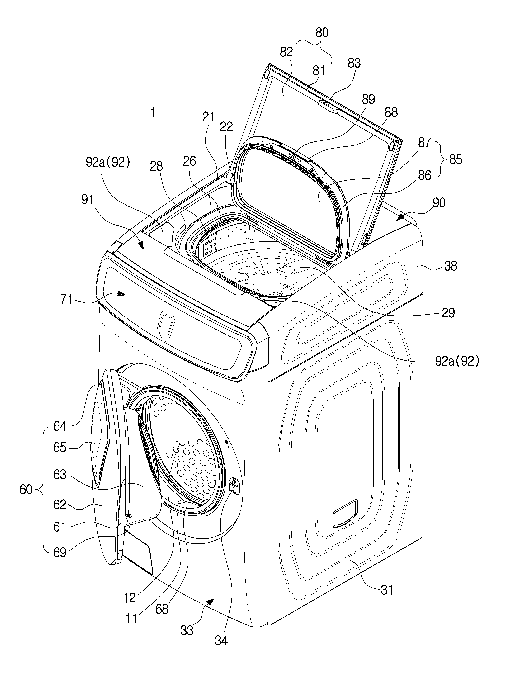
structure.
[81 Additional aspects of the disclosure will be set forth in part in the
description which
follows and, in part, will be obvious from the description, or may be learned
by
practice of the disclosure.
Solution to Problem
191 In accordance with one aspect of the present disclosure, a washing
machine includes
a first housing; a second housing disposed on the first housing; a first tub
included the
2
CA 03048166 2019-06-21
WO 2018/117490 PCT/KR2017/014212
first housing and having a first opening formed at a front surface thereof; a
second tub
included the second housing and having a second opening formed at an upper
surface
thereof; a drain path to drain wash water from the first tub and wash water
from the
second tub and having at least one portion located at a position higher than a
maximum
water storage height of the second tub; and a connector coupled to the first
housing and
disposed at one portion of the drain path where the wash water of the first
tub and the
wash water of the second tub are joined.
[10] The drain path may include a first drain path through which the wash
water from the
first tub flows to the connector; a second drain path through which the wash
water
from the second tub flows to the connector; and a third drain path through
which wash
water introduced into the connector through the first drain path and the
second drain
path flows out from the connector.
[11] At least one portion of the third drain path may be located at a
position higher than
the maximum water storage height of the second tub.
[12] The connector may include a first inlet pipe to form the second drain
path; and a first
check valve detachable from or attachable to the first inlet pipe and
configured to
prevent a backflow of the wash water from the second tub in a direction
opposite to a
drain direction.
[13] The first check valve may include a sealing protrusion which protrudes
from a
surface in contact with the first inlet pipe.
[14] The washing machine may further include a drain bracket disposed in
the first
housing, coupled to the connector, and having an insertion pipe inserted into
the first
check valve.
[15] The connector may include a second check valve disposed at the first
drain path and
configured to prevent a backflow of the wash water from the first tub in a
direction
opposite to the drain direction.
[16] The connector further comprises a second inlet pipe to form the first
drain path and
The second check valve may be detachable from or attachable to the second
inlet pipe
of the connector.
[17] At least one of the first check valve and the second check valve may
be formed of an
elastic material.
[18] At least one portion of the second drain path may be located at a
position higher than
the maximum water storage height of the second tub.
[19] The connector may include a guide rib disposed at a portion thereof
where the first
drain path and the second drain path are joined and configured to guide the
wash water
introduced into the connector through the first drain path to the third drain
path to
prevent a backflow of the wash water introduced into the connector through the
first
drain path into the first tub.
3
CA 03048166 2019-06-21
WO 2018/117490 PCT/KR2017/014212
[20] The connector may further include a first check valve disposed at the
second drain
path and configured to prevent a backflow of the wash water from the second
tub in a
direction opposite to the drain direction.
[21] The connector may further include a second check valve formed at the
third drain
path and configured to prevent a backflow of the wash water from the first tub
in a
direction opposite to the drain direction.
[22] At least one portion of the first drain path may be located at a
position higher than a
maximum water storage height of the first tub.
[23] The connector may be coupled to an outer portion of the first housing
at a position
higher than a maximum water storage height of the first tub.
[24] In accordance with another aspect of the present disclosure, a washing
machine
includes a first housing; a second housing disposed on the first housing; a
first tub
included in the first housing; a second tub included in the second housing; a
first drain
path through which wash water from the first tub flows; a second drain path
through
which wash water from the second tub flows; a connector disposed at a portion
where
the first drain path and the second drain path are joined; and a third drain
path through
which the wash water introduced into the connector through the first drain
path and the
second drain path flows out, wherein at least one portion of the third drain
path is
located at a position higher than a maximum water storage height of the second
tub.
[25] The connector may includes a first inlet pipe forming the second drain
path; a second
inlet pipe forming the first drain path; a first check valve detachably
coupled to the
first inlet pipe and configured to prevent a backflow of wash water in a
direction
opposite to a drain direction; and a second check valve detachably coupled to
the
second inlet pipe and configured to prevent a backflow of wash water in a
direction
opposite to a drain direction.
[26] The first check valve may comprise a sealing protrusion which
protrudes from a
surface in contact with the first inlet pipe.
[27] In accordance with still another aspect of the present disclosure, a
washing machine
includes a first housing; a second housing disposed on the first housing; a
first tub
included in the first housing; a second tub included in the second housing; a
first drain
path through which wash water from the first tub flows; a second drain path
through
which wash water from the second tub flows; a connector disposed at a portion
where
the first drain path and the second drain path are joined; and a third drain
path through
which the wash water introduced into the connector through the first drain
path and the
second drain path flows out, wherein at least one portion of the second drain
path is
located at a position higher than a maximum water storage height of the second
tub.
[28] The connector may includes a guide rib disposed at a portion thereof
where the first
drain path and the second drain path are joined and configured to guide the
wash water
4
CA 03048166 2019-06-21
WO 2018/117490 PCT/KR2017/014212
introduced into the connector through the first drain path to the third drain
path to
prevent a backflow of the wash water introduced into the connector through the
first
drain path into the first tub; and a first check valve disposed at the second
drain path
and configured to prevent a backflow of the wash water from the second tub in
a
direction opposite to a drain direction.
Advantageous Effects of Invention
[29] As is apparent from the above description, according to the washing
machine
according to the present disclosure, laundry may be washed separately, if
required, by
using a plurality of washing apparatuses.
[30] According to the washing machine according to the present disclosure,
manu-
facturing costs may be reduced since wash water is drained by using a single
drain
hose by connecting drain hoses to drain wash water of the plurality of tubs
with each
other using a connector.
[31] According to the washing machine according to the present disclosure,
siphonage
among the plurality of washing apparatuses may be prevented without using a
separate
control valve by disposing at least one portion of a drain path at a position
higher than
a maximum water storage height of an upper tub.
Brief Description of Drawings
[32] FIG. 1 is a perspective view illustrating a washing machine according
to an em-
bodiment.
[33] FIG. 2 is an exploded perspective view of the washing machine of FIG.
1.
[34] FIG. 3 is a cross-sectional view of the washing machine illustrated in
FIG. 1.
[35] FIG. 4 is a rear view of the washing machine of FIG. 1 illustrating a
drain path.
[36] FIG. 5 is an exploded view of a connector and a drain bracket shown in
FIG. 4.
[37] FIG. 6 is a cross-sectional view illustrating a coupled state of the
connector and the
drain bracket shown in FIG. 4.
[38] FIG. 7 is a view illustrating another example of the second drain hose
of the washing
machine illustrated in FIG. 4.
[39] FIG. 8 is a rear view of a drain path of a washing machine according
to another em-
bodiment of the present disclosure.
[40] FIG. 9 is a cross-sectional view of a connector illustrated in FIG. 8.
[41] FIG. 10 is a view illustrating another example of the first drain hose
of the washing
machine illustrated in FIG. 8.
[42] FIG. 11 is a rear view illustrating a drain path of a washing machine
according to
another embodiment of the present disclosure.
[43] FIG. 12 is a cross-sectional view of a connector illustrated in FIG.
11.
[44] FIG. 13 is a view illustrating another example of the connector
illustrated in FIG. 12.
5
CA 03048166 2019-06-21
WO 2018/117490 PCT/KR2017/014212
Mode for the Invention
[45] Reference will now be made in detail to the embodiments of the present
disclosure,
examples of which are illustrated in the accompanying drawings. The
embodiments
described in the specification and shown in the drawings are only illustrative
and are
not intended to represent all aspects of the invention, such that various
modifications
may be made without departing from the spirit of the invention.
[46] In the drawings, like reference numerals denote like elements or
components having
substantially same functions.
[47] The terms used in the present specification are merely used to
describe particular em-
bodiments, and are not intended to limit the present disclosure. An expression
used in
the singular encompasses the expression of the plural, unless it has a clearly
different
meaning in the context. In the present specification, it is to be understood
that the
terms such as "including" or "having", etc., are intended to indicate the
existence of the
features, numbers, operations, components, parts, or combinations thereof
disclosed in
the specification, and are not intended to preclude the possibility that one
or more other
features, numbers, operations, components, parts, or combinations thereof may
exist or
may be added.
[48] It will be understood that, although the terms "first", "second",
etc., may be used
herein to describe various elements, these elements should not be limited by
these
terms. The above terms are used only to distinguish one component from
another. For
example, a first component discussed below could be termed a second component,
and
similarly, the second component may be termed the first component without
departing
from the teachings of this disclosure. As used herein, the term "and/or"
includes any
and all combinations of one or more of the associated listed items.
[49] Meanwhile, as used herein, the terms "front", "rear", "up", "down",
"front end",
"lower end", and the like are defined based on the drawings and the shape and
position
of each element are not limited by these terms.
[50] Hereinafter, embodiments of the present disclosure will be described
in detail with
reference to the accompanying drawings.
[51] FIG. 1 is a perspective view illustrating a washing machine 1
according to an em-
bodiment. FIG. 2 is an exploded perspective view of the washing machine 1 of
FIG. 1.
FIG. 3 is a cross-sectional view of the washing machine 1 illustrated in FIG.
1.
[52] As shown in FIGS. 1 and 2, the washing machine 1 may include a front-
loading first
washing apparatus having a first laundry loading port 11 formed at a front
portion and
a top-loading second washing apparatus having a second laundry loading port 21
formed at a top portion.
[53] The washing machine 1 may include a first drum 13 having a first
washing space 12
6
CA 03048166 2019-06-21
WO 2018/117490 PCT/KR2017/014212
therein, and a first tub 14 that accommodates the first drum 13 and retains
wash water
or rinse water used in a washing cycle or rinsing cycle. The first drum 13 and
the first
tub 14 may have a cylindrical shape with at least a portion of one surface
being open
which faces forward. The first tub 14 may have a first opening 14a formed to
face ap-
proximately forward.
[54] The washing machine 1 may include a first housing 30 that covers the
first drum 13
and the first tub 14. Specifically, the first housing 30 may include a side
frame 31
defining side and rear appearances and a bottom frame 32 defining a bottom
surface.
[55] The washing machine 1 may further include a damper 15 and a spring 16
to support
the first tub 14 with respect to the first housing 30. The damper 15 may
support the
first tub 14 under the first tub 14 by connecting an outer surface of the
first tub 14 with
the bottom frame 32. The spring 16 may support the first tub 14 on an upper
portion of
the first tub 14 by connecting the outer surface of the first tub 14 with an
upper end of
the side frame 31. The damper 15 and the spring 16 may relieve vibration,
noise, and
impact caused by movement of the first tub 14.
[56] Installation positions of the damper 15 and the spring 16 are not
limited to the upper
end of the side frame 31 and the bottom frame 32. If required, the first tub
14 may be
supported thereby by connecting one surface of the first tub 14 with one
portion of the
first housing 30.
[57] The washing machine 1 may include a first drive motor 40 disposed
behind a rear
plate of the first tub 14 and configured to rotate the first drum 13. A first
drive shaft 41
may be connected to the rear plate of the first drum 13 to transmit power of
the first
drive motor 40 thereto.
[58] A plurality of first through holes 13a may be formed through a
peripheral wall of the
first drum 13 to allow a flow of wash water therethrough. A plurality of
lifters 13b may
be installed on an inner surface of the peripheral wall of the first drum 13
to allow
tumbling of laundry during rotation of the first drum 13. A first balancer 17
may be
provided at a front end of the first drum 13 for stable rotation of the first
drum 13
during high-speed rotation.
[59] The first drive shaft 41 may be disposed between the first drum 13 and
the first drive
motor 40. One end of the first drive shaft 41 may be connected to the rear
plate of the
first drum 13 and the other end of the first drive shaft 41 may extend
outwardly from a
rear wall of the first tub 14. When the first drive motor 40 drives the first
drive shaft
41, the first drum 13 connected to the first drive shaft 41 may rotate about
the first
drive shaft 41.
[60] A bearing housing 42 may be disposed at the rear wall of the first tub
14 to allow
rotation of the first drive shaft 41. The bearing housing 42 may be formed of
an
aluminum alloy and inserted into the rear wall of the first tub 14 during
injection
7
CA 03048166 2019-06-21
WO 2018/117490 PCT/KR2017/014212
molding of the first tub 14. Bearings 43 may be provided between the bearing
housing
42 and the first drive shaft 41 for smooth rotation of the first drive shaft
41.
[61] The washing machine 1 may have a function of washing the laundry with
hot water.
In order to obtain hot water, a heater 18 that heats wash water or rinse water
contained
in the first tub 14 may be provided at the bottom of the first tub 14.
[62] The washing machine 1 may include a first drain pump 50 disposed at
the bottom of
the first tub 14 and configured to drain water contained in the first tub 14
out of the
washing machine 1, a first connection hose 52 connecting a first drain hole 51
and the
first drain pump 50 to allow water contained in the first tub 14 to flow into
the first
drain pump 50, a circulation hose 53 connecting the first drain pump 50 and
the first
tub 14 to circulate water introduced into the first drain pump 50 to the first
tub 14, and
a first drain hose 54 configured to guide water pumped by the first drain pump
50 to a
connector 110.
[63] The washing machine 1 may include a front cover 33 having the first
laundry loading
port 11 through which laundry is loaded into the first washing space 12. A
first door 60
configured to open and close the first laundry loading port 11 may be coupled
to the
front cover 33.
[64] The first door 60 may be formed so as to correspond to the first
laundry loading port
11 and be pivotally rotatable about the front cover 33. The first door 60 may
include a
first door frame 61, a first door cover 62, and a door glass 63.
[65] The first door frame 61 is formed in an approximately annular shape
according to the
present embodiment, the shape of the first door 60 may be approximately
rectangular.
The first door cover 62 and the door glass 63 may be formed of a transparent
material
such that the inside of the first drum 13 is visible from the outside of the
washing
machine 1 even when the first door 60 closes the first laundry loading port
11. The
door glass 63 may be disposed to protrude from the first door frame 61 toward
the
inside of the first drum 13. According to this configuration, when the first
door 60 is
closed, the door glass 63 may be inserted into the first laundry loading port
11.
[66] The first door 60 may include a first hinge coupling portion formed at
one side of the
first door frame 61 to be pivotally rotatable with respect to the front cover
33 and the
first hinge coupling portion may be coupled to a first hinge disposed to be
adjacent to
the first laundry loading port 11. A first hook 69 may be provided at the
other side of
the first door frame 61. The front cover 33 may have a first hook receiving
portion 34
corresponding to the first hook 69 such that the first door 60 is maintained
in a state of
closing the first laundry loading port 11.
[67] The first door 60 may further include an auxiliary laundry loading
port 64 and an
auxiliary door 65 configured to open and close the auxiliary laundry loading
port 64
such that laundry is loaded into the first washing space 12 even when the
first door 60
8
CA 03048166 2019-06-21
WO 2018/117490 PCT/KR2017/014212
is closed. The auxiliary door 65 may be rotatably mounted to the first door
cover 62.
[68] In order to load laundry into the washing machine 1 through the
auxiliary laundry
loading port 64 of the first door 60, the laundry should pass through the door
glass 63.
To this end, the door glass 63 may have a glass through hole 66.
Alternatively, the
door glass 63 may be recessed at an upper portion such that the door glass 63
is not
disposed behind the auxiliary laundry loading port 64.
[69] The first door 60 may have a connection guide part 67 to connect the
auxiliary
laundry loading port 64 of the first door 60 and the glass through hole 66 of
the door
glass 63. The connection guide part 67 may be formed in a hollow tubular shape
having both open ends.
[70] Specifically, one end of the connection guide part 67 may be connected
to the
auxiliary laundry loading port 64 and the other end may be connected to the
glass
through hole 66. According to the present embodiment, the connection guide
part 67
may be inclined downward from the front to the rear. That is, the one end of
the
connection guide part 67 connected to the auxiliary laundry loading port 64
may be po-
sitioned higher than the other end thereof. According to this configuration, a
user may
easily load the laundry into the first drum 13 through the auxiliary laundry
loading port
64.
[71] Although the first door 60 includes the auxiliary door 65 according to
the present em-
bodiment, the present disclosure is not limited thereto and the first door 60
may be
configured without having the auxiliary laundry loading port 64, the auxiliary
door 65,
and the connection guide part 67.
[72] The washing machine 1 may include a diaphragm 68 disposed between the
first
laundry loading port 11 of the front cover 33 and the first opening 14a of the
first tub
14. The diaphragm 68 may form a passage from the first laundry loading port 11
to a
third opening 13c of the first drum 13 and decrease vibration transmitted to
the front
cover 33 during rotation of the first drum 13. Also, one portion of the
diaphragm 68
may be disposed between the first door 60 and the front cover 33 to prevent
leakage of
wash water contained in the first tub 14 out of the washing machine 1.
[73] The washing machine 1 may include a second drum 23 having a second
washing
space 22 and a second tub 24 that accommodates the second drum 23 and retains
wash
water or rinse water used in a washing cycle or rinsing cycle. The second drum
23 and
the second tub 24 may have a cylindrical shape with at least a portion of one
surface
being open which faces upward. The second tub 24 may have a second opening 26
formed to face approximately upward.
[74] The washing machine 1 may include a second housing 35 that covers the
second
drum 23 and the second tub 24. Specifically, the second housing 35 may include
a
lower frame 36 configured to support the second tub 24 and an upper frame 37
having
9
CA 03048166 2019-06-21
WO 2018/117490 PCT/KR2017/014212
a second laundry loading port 21 through which laundry is loaded into the
second
washing space 22 and seated on the lower frame 36.
[75] The side cover 38 simplifies side surfaces of the second housing 35 by
covering left
and right sides of the lower frame 36 and the upper frame 37 by using one
member.
When the lower frame 36 and the upper frame 37 are disassembled by vibration
or the
like, the side cover 38 may prevent dislocation thereof, thereby inhibiting
the user from
being injured thereby.
[76] The washing machine 1 may include a second door 80 disposed at the
second
housing 35 and configured to open and close the second laundry loading port
21. The
second door 80 may be formed so as to correspond to the second laundry loading
port
21 and be pivotally rotatable with respect to the upper frame 37.
[77] The second door 80 may include a second door frame 81 and a second
door cover 82.
The second door cover 82 may be formed of a transparent material such that the
inside
of the second tub 24 and the second drum 23 is visible from the outside of the
washing
machine 1 even when the second door 80 closes the second laundry loading port
21.
[78] Second hinges (not shown) may be provided at the left and right sides
of the second
door frame 81 to allow the second door 80 to pivotally rotate about the upper
frame 37.
The second hinge may be coupled to a second hinge coupling portion (not shown)
formed around the second laundry loading port 21. A latch receiving part 83
may be
provided at the front end of the second door frame 81 and a latch unit may be
provided
at the upper frame 37 to correspond to the latch receiving part 83 of the
second door
frame 81. According to this configuration, the second door 80 of the washing
machine
1 according to the present embodiment may be maintained in a state of closing
the
second laundry loading port 21.
[79] The second drum 23 may be provided in a cylindrical shape having an
open top
surface and rotatable within the second tub 23. A plurality of through holes
23a may be
formed through a side surface and/or a bottom surface of the second drum 23 to
allow
a flow of wash water therethrough. A second balancer 27 may be mounted at an
upper
portion of the second drum 23 for stable rotation of the second drum 23 during
high-
speed rotation. A filter 28 may be attached to the inner surface of the second
drum 23
so as to remove foreign substances during washing.
[80] A curved portion 29 to generate water streams may be formed on the
bottom surface
of the second drum 23. Although not shown in the drawings, the washing machine
1
may further include a pulsator disposed in the second drum 23 to generate
water
streams.
[81] The second tub 24 may be provided in a cylindrical shape and supported
by the lower
frame 36 via a suspension 25. Specifically, the second tub 24 may be supported
in the
form of being hung by four suspensions 25. The second drum 23 may have a
second
10
CA 03048166 2019-06-21
WO 2018/117490 PCT/KR2017/014212
opening 26 formed at a top surface thereof to correspond to the second laundry
loading
port 21 and a third door 85 may be coupled thereto to open and close the
second
opening 26. The third door 85 may seal the second washing space 22 to prevent
leakage of wet steam while the second washing apparatus performs a washing
cycle
using hot wash water.
[82] The third door 85 may include a third door frame 86 and a third door
cover 87. The
third door cover 87 may be formed of a transparent material such that the
inside of the
second drum 23 is visible from the outside of the second tub 24 even when the
third
door 85 closes the second opening 26.
[83] A third hinge (not shown) may be provided around the second opening 26
such that
the third door 85 is pivotally rotatable with the second tub 24 and coupled to
a third
hinge coupling portion (not shown) formed at one side of the third door frame
86. A
handle 88 to open and close the third door 85 may be provided at the other
side of the
third door frame 86 and a second hook 89 may be provided at the handle 88. A
second
hook receiving part (not shown) may be disposed at the second tub 24 to
correspond to
the second hook 89. Accordingly, the third door 85 may be maintained in a
state of
closing the second opening 26. In addition, when the handle 88 is pulled, the
second
hook 89 is disengaged from the second hook receiving part so that the third
door 85
may completely open the second washing space 22.
[84] The washing machine 1 may include a second drive motor 45 disposed
under a
bottom plate of the second tub 24 and configured to rotate the second drum 23.
A
second drive shaft 46 may be connected to the bottom plate of the second drum
23 to
transmit power of the second drive motor 45 thereto. One end of the second
drive shaft
46 may be connected to the bottom plate of the second drum 23 and the other
end of
the second drive shaft 46 may extend outward from a bottom wall of the second
tub 24.
When the second drive motor 45 drives the second drive shaft 46, the second
drum 23
connected to the second drive shaft 46 may rotate about the second drive shaft
46.
[85] Although not shown in the drawings, when the pulsator is disposed on
the bottom
surface of the second drum 23, the washing machine 1 may further include a
power
switching device to transmit power generated by the second drive motor 45
simul-
taneously or selectively to the second drum 23 and the pulsator.
[86] The washing machine 1 may include a second drain pump 55 disposed at
the bottom
of the second tub 24 and configured to drain water contained in the second tub
24 out
of the washing machine 1 and a second drain hose 59 configured to guide the
water
pumped by the second drain pump 55 to the connector 110. The second drain pump
55
may be mounted to an upper portion of the first housing 30.
[87] A second drain hole 56 to drain water from the second tub 24 may be
disposed at the
bottom of the second tub 24 and the second drain hole 56 may be connected to
the
11
CA 03048166 2019-06-21
WO 2018/117490 PCT/KR2017/014212
second drain pump 55 via a second connection hose 57 to allow water contained
in the
second tub 24 into the second drain pump 55.
[88] The washing machine 1 may include a water supply device 90 to supply
wash water
into the first tub 14 and the second tub 24. The water supply device 90 may be
disposed at the second housing 35. Specifically, the water supply device 90
may be
disposed at the upper frame 37, preferably, behind the second laundry loading
port 21.
[89] The washing machine 1 may further include a first detergent feed
device 91 to feed a
detergent into the first tub 14. The first detergent feed device 91 may be
disposed at the
second housing 35. Specifically, the first detergent feed device 91 may be
disposed at
the upper frame 37, preferably in front of the second laundry loading port 21.
[90] The washing machine 1 may include a second detergent feed device 92
disposed at
the second housing 35 and configured to retain a fabric softener and/or a
bleach to be
fed into the second washing space 22. The second detergent feed device 92 may
be
disposed at the upper frame 37 and include a detergent case 92a having an
opening that
faces approximately upward. The second detergent feed device 92 may be
disposed at
left and right ends of the front of the second opening 26 respectively. The
second
detergent feed device 92 may be provided to allow the user to access thereto
by
opening the second door 80.
[91] The washing machine 1 may include a fixing bracket 70 that couples the
first housing
30 and the second housing 35 so as not to be separated from each other.
[92] The washing machine 1 may include a control panel 71 disposed on the
front cover
33 and configured to operate the washing machine 1. The control panel may
include an
input unit (not shown) to receive an operation command of the washing machine
1
from the user and a display unit (not shown) to display operation information
of the
washing machine 1.
[93] FIG. 4 is a rear view of the washing machine 1 of FIG. 1 illustrating
a drain path P.
FIG. 5 is an exploded view of a connector 110 and a drain bracket 120 shown in
FIG.
4. FIG. 6 is a cross-sectional view illustrating a coupled state of the
connector 110 and
the drain bracket 120 shown in FIG. 4.
[94] Referring to FIGS. 4 to 6, a drain path P of wash water from the first
tub 14 and the
second tub 24 of the washing machine 1 according to an embodiment will be
described. Hereinafter, the drain path P is defined to include a flow path
through which
wash water of the first tub 14 flows out of the washing machine 1 and a flow
path
through which wash water of the second tub 24 flows out of the washing machine
1.
[95] The drain path P of the washing machine 1 according to the present
embodiment may
include a first drain path P1 through which wash water of the first tub 14
flows to the
connector 110, a second drain path P2 through which wash water of the second
tub 24
flows to the connector 110, and a third drain path P3 through which wash water
in-
12
CA 03048166 2019-06-21
WO 2018/117490 PCT/KR2017/014212
troduced into the connector 110 out of the washing machine 1. In this regard,
at least
one portion of the drain path P may be located at a higher position than a
maximum
water storage height H1 of the second tub 24.
[96] Specifically, the first drain path P1 is a part of the flow path for
draining wash water
of the first tub 14 and may be defined by the first drain hole 51, the first
connection
hose 52, the first drain pump 50, the first drain hose 54, and a second inlet
pipe 112 of
the connector 110. Wash water of the first tub 14 may flow to the connector
110 via
the first drain path Pl.
[97] The second drain path P2 is a part of the flow path for draining wash
water of the
second tub 24 and may be defined by the second drain hole 56, the second
connection
hose 57, the second drain pump 55, the second drain hose 59, and a first inlet
pipe 111
of the connector 110. Wash water of the second tub 24 may flow to the
connector 110
through the second drain path P2.
[98] The third drain path P3 is a flow path for draining both wash water of
the first tub 14
and wash water of the second tub 24 and may be defined by an outlet 113 of the
connector 110 and a third drain hose 101. Wash water introduced into the
connector
110 through the first drain path P1 and the second drain path P2 may flow out
of the
washing machine 1 through the third drain path P3.
[99] In the washing machine 1 according to the present embodiment, at least
one portion
of the third drain path P3 may be located at a position H2 higher than the
maximum
water storage height H1 of the second tub 24. Specifically, at least one
portion of the
third drain hose 101 constituting the third drain path P3 may be fixed to the
position
H2 higher than the maximum water storage height H1 of the second tub 24. To
this
end, the washing machine 1 may include a fixing member 102 to fix the one
portion of
the third drain hose 101. The fixing member 102 may fix the third drain hose
101 to
the second housing 35.
[100] According to this configuration, the washing machine 1 according to
an embodiment
may prevent wash water supplied into the second tub 24 from being drained
through
the third drain path P3 while water is supplied into the second tub 24.
[101] That is, since a separate electronic control valve is not disposed at
the second drain
path P2 in the washing machine 1 according to an embodiment, wash water is
filled in
the second drain hole 56, the second connection hose 57, the second drain pump
55,
the second drain hose 59, the connector 110, and the third drain hose 101 at
the same
height as that of the second tub 24 while water is supplied into the second
tub 24. In
this case, if the third drain hose 101 is located at a lower position than the
maximum
water storage height H1 of the second tub 24, wash water filled in the third
drain hose
101 starts to be drained out of the washing machine 1. Accordingly, all of the
wash
water of the second tub 24 may be drained out of the washing machine 1 by
siphonage.
13
CA 03048166 2019-06-21
WO 2018/117490 PCT/KR2017/014212
[102] Thus, at least one portion of the third drain path P3 may be disposed
at a position H2
higher than the maximum water storage height H1 of the second tub 24 in the
washing
machine 1 according to the present embodiment. In this case, wash water does
not fill
the entire third drain path P3 of the washing machine 1, so that the loss of
wash water
of the second tub 24 caused by siphonage may be prevented even when water is
supplied into the second tub 24.
[103] The washing machine 1 according to an embodiment may include the
connector 110
that connects the first drain path Pi, the second drain path P2, and the third
drain path
P3. The connector 110 may be coupled to the first housing 30, particularly, to
the side
frame 31. The connector 110 may be provided at the drain path P. The connector
110
may be located at one portion of the drain path P where wash water of the
first tub 14
and wash water of the second tub 24 are joined. The connector 110 may guide
wash
water flowing in the first drain path P1 and wash water flowing in the second
drain
path P2 to be joined and flow into the third drain path P3.
[104] The connector 110 may include the first inlet pipe 111 forming the
second drain path
P2, the second inlet pipe 112 forming the first drain path Pi, and an outlet
113 forming
the third drain path P3.
[105] The first inlet pipe 111 may be coupled to the first housing 30
together with the drain
bracket 120, which will be described later. The first inlet pipe 111 may be
coupled to
the first housing 30 via a fixing part 115 provided at one portion of the
outer circum-
ferential surface. The fixing part 115 may be coupled to the first housing 30
by screw
coupling. Accordingly, the connector 110 may be easily separated from the
first
housing 30 and easily maintained and repaired.
[106] The second inlet pipe 112 may be connected to the first drain hose
54. Specifically,
the second inlet pipe 112 may be connected to the first drain hose 54 by the
first
connection member 54a.
[107] The outlet 113 may be connected to the third drain hose 101.
Specifically, the outlet
113 may be connected to the third drain hose 101 by the second connection
member
101a. The third drain hose 101 may extend such that wash water is drained from
an
upper portion of the washing machine 1. Alternatively, the third drain hose
101 may
also extend such that wash water is drained from a lower portion of the
washing
machine 1.
[108] The connector 110 may include a first check valve 116 detachably
coupled to the
first inlet pipe 111 and configured to prevent a backflow of wash water in a
direction
opposite to a drain direction. The first check valve 116 may be formed of an
elastic
material. Specifically, the first check valve 116 may be a duckbill valve
formed of
rubber or a synthetic elastomer.
11091 The first check valve 116 may allow wash water to flow in a
predetermined direction
14
CA 03048166 2019-06-21
WO 2018/117490 PCT/KR2017/014212
in the second drain path P2 without using a separate control device. That is,
a first
opening/closing unit 116a of the first check valve 116 is opened by a pressure
of wash
water to open the second drain path P2 in the case where wash water flows in
the drain
direction in the second tub 24 and returns to an original shape thereof by a
force of
restoration to close the second drain path P2 in the case where wash water
flows in the
direction opposite to the drain direction.
[110] The first check valve 116 may include a first sealing protrusion 116b
protruding from
a surface in contact with the first inlet pipe 111. The first sealing
protrusion 116b may
seal a gap between the first inlet pipe 111 and the first check valve 116 so
that leakage
of water from a joined portion of the first inlet pipe 111 and the first check
valve 116.
[111] The first sealing protrusion 116b of the first check valve 116 may
also protrude from
a surface in contact with the drain bracket 120. Thus, the first sealing
protrusion 116b
may seal a gap between the first check valve 116 and the drain bracket 120 so
that
leakage of water may be prevented from a joined portion of the first check
valve 116
and the drain bracket 120.
[112] Although the first check valve 116 coupled to the connector 110 has
been described
above, the position of the first check valve 116 is not limited thereto and
the first check
valve 116 may also be disposed at the second drain path P2 to prevent a
backflow of
wash water in the second drain path P2.
[113] The connector 110 may include a second check valve 117 detachably
coupled to the
second inlet pipe 112 and configured to prevent a backflow of wash water in a
direction opposite to the drain direction. However, the position of the second
check
valve 117 is not limited thereto, and the second check valve 117 may also be
disposed
at the first drain path P1 to prevent a backflow of wash water in the first
drain path Pl.
The second check valve 117 may be configured in the same manner as the first
check
valve 116. That is, the second check valve 117 may include a second
opening/closing
unit 117a having the same functions as the first opening/closing unit 116a of
the first
check valve 116. In addition, the second check valve 117 may include a second
sealing
protrusion (not shown) having the same functions as the first sealing
protrusion 116a
of the first check valve 116.
[114] The washing machine 1 may include the drain bracket 120 disposed
inside the first
housing 30, coupled to the connector 110, and including an insertion pipe 121
inserted
into the first check valve 116. One end of the drain bracket 120 provided with
the
insertion pipe 121 may be connected to the first check valve 116 and the other
end of
the drain bracket 120 opposite thereto may be connected to the second drain
hose 59.
The drain bracket 120 may be connected to the connector 110 with the side
frame 31
disposed therebetween. The insertion pipe 121 may be disposed to penetrate the
first
housing 30.
15
CA 03048166 2019-06-21
WO 2018/117490 PCT/KR2017/014212
[115] According to this configuration, wash water of the first tub 14 of
the washing
machine 1 according to the present embodiment may be drained out of the
washing
machine 1 through the first drain path Pl, the connector 110, and the third
drain path
P3 by power of the first drain pump 50, and wash water of the second tub 24
may be
drained out of the washing machine 1 through the second drain path P2, the
connector
110, and the third drain path P3 by power of the second drain pump 55. Also,
when the
third drain hose 101 extends upward in the washing machine 1, the first check
valve
116 may prevent a backflow of wash water remaining in the third drain hose 101
into
the second tub 24 and the second check valve 117 may prevent a backflow of
wash
water remaining in the third drain hose 101 into the first tub 14.
[116] According to this configuration, the connector 110 is directly
coupled to the first
housing 30, and thus the washing machine 1 appears to have a single drain path
P
when viewed from the outside of the washing machine 1. Therefore, an
integrated ap-
pearance may be given although the washing machine 1 includes a plurality of
washing
apparatuses.
[117] In addition, since the first check valve 116 is disposed at the
second drain path P2 in
the washing machine 1, a backflow of wash water into the second tub 24 may be
prevented by using the simple structure.
[118] Also, since the second check valve 117 is disposed at the first drain
path P1 in the
washing machine 1, a backflow of wash water into the first tub 14 may be
prevented
by using the simple structure.
[119] FIG. 7 is a view illustrating another example of the second drain
hose 59 of the
washing machine 1 illustrated in FIG. 4.
[120] In the washing machine 1 according to an embodiment, at least one
portion of a
second drain hose 59a may be disposed at a position H3 higher than the maximum
water storage height H1 of the second tub 24. That is, at least one portion of
the second
drain path P2 may be located at the position H3 higher than the maximum water
storage height H1 of the second tub 24.
[121] According to this configuration, the washing machine 1 may prevent
wash water
from being drained out of the washing machine 1 through the drain path P while
water
is supplied into the second tub 24. That is, even when the second tub 24 is
filled up to a
maximum height, wash water cannot pass through the second drain hose 59a and
flow
into the connector 110. Thus, the washing machine 1 may prevent wash water
from
being drained out of the washing machine 1 through the third drain path P3 by
siphonage.
[122] FIG. 8 is a rear view of a drain path P of a washing machine 2
according to another
embodiment of the present disclosure. FIG. 9 is a cross-sectional view of a
connector
210 illustrated in FIG. 8.
16
CA 03048166 2019-06-21
WO 2018/117490 PCT/KR2017/014212
[123] Referring to FIGS. 8 and 9, the washing machine 2 will be described.
The same
reference numerals are given to the same components as components described
above
with reference to FIGS. 4 to 6, and descriptions thereof will not be repeated.
[124] The connector 210 of the washing machine 2 may be coupled to the
first housing 30,
particularly, the first drain hose 54 through which wash water of the first
tub 14 is
drained. In this case, the connector 210 may be disposed at a position H6
higher than a
maximum water storage higher H5 of the first tub 14. That is, the first drain
hose 54
may be connected to a first inlet pipe 211 of the connector 210 at the
position H6
higher than the maximum water storage higher H5 of the first tub 14.
[125] Also, in this case, at least one portion of the second drain path P2
may be disposed at
a position H4 higher than the maximum water storage height H1 of the second
tub 24
to prevent the loss of wash water from the second tub 24 by siphonage.
[126] In this case, the second drain path P2 may be defined by the second
drain hole 56, the
second connection hose 57, the second drain pump 55, the second drain hose 59,
an
auxiliary pipe 206, an auxiliary hose 207, and a second inlet pipe 212 of the
connector
210. That is, the washing machine 2 may include the auxiliary pipe 206 and the
auxiliary hose 207 unlike the embodiment illustrated in FIG. 4.
[127] The auxiliary pipe 206 penetrates the first housing 30. One end of
the auxiliary pipe
206 may be connected to the second drain hose 59 and the other end may be
connected
to the auxiliary hose 207.
[128] One end of the auxiliary hose 207 may be connected to the auxiliary
pipe 206, and
the other end opposite thereto may be connected to the second inlet pipe 212
of the
connector 210. Also, at least one portion of the auxiliary hose 207 may be
disposed at
the position H4 higher than the maximum water storage height H1 of the second
tub
24. That is, at least one portion of the auxiliary hose 207 may be fixed to
the second
housing 35 by a fixing member 202 at the position H4 higher than the maximum
water
storage height H1 of the second tub 24.
[129] However, the auxiliary pipe 206 may be omitted and thus the second
drain hose 59
may extend to the second inlet pipe 212 of the connector 210 such that one
portion of
the second drain hose 59 is disposed at the position H4 higher than the
maximum water
storage height H1 of the second tub 24. In this case, one portion of the
second drain
hose 59 may be fixed to the second housing 35 by a fixing device such as a
clamp.
[130] The third drain path P3 may be defined by an outlet 213 of the
connector 210 and a
third drain hose 208. The third drain hose 208 may extend such that wash water
is
drained downward from the washing machine 2.
[131] The connector 210 may include the first inlet pipe 211 forming the
first drain path
Pl, the second inlet pipe 212 forming the second drain path P2, and the outlet
213
forming the third drain path P3. The connector 210 may be coupled and fixed to
the
17
CA 03048166 2019-06-21
WO 2018/117490 PCT/KR2017/014212
first housing 30 by a fixing part 215. The fixing part 215 may be coupled to
the first
housing 30 by screw coupling. The connector 210 may be coupled to an outer
portion
of the first housing 30 at a position H6 higher than the maximum water storage
height
H5 of the first tub 14.
[132] The connector 210 may include a guide rib 214 disposed at a position
where the first
drain path P1 and the second drain path P2 are joined and preventing a
backflow of
wash water into the first tub 14. The guide rib 214 may protrude from an inner
surface
of the connector 210 and extend in a drain direction of wash water. The guide
rib 214
may partition an inner space of the connector 210.
[133] The washing machine 2 may include a draying apparatus 76 that
supplies hot air to
dry laundry contained in the first tub 14. The drying apparatus 76 may be
connected to
the first tub 14 via a drying hose 77.
[134] The washing machine 2 may further include a sub hose 78 to discharge
hot air
supplied by the drying apparatus 76. The sub hose 78 may be connected to the
first
drain hose 54 in the first housing 30. That is, hot air contained in the first
tub 14 may
flow to the first drain hose 54 via the sub hose 78 and then discharged out of
the
washing machine 2 through the drain path P. In order to efficiently discharge
the hot
air of the first tub 14 out of the washing machine 2 through the first inlet
pipe 211 and
the third drain path P3, the first inlet pipe 211 may dispense with the first
check valve
116 illustrated in FIGS. 4 to 6.
[135] The connector 210 may include a first check valve 216 disposed at the
second drain
path P2 and configured to prevent a backflow of wash water in a direction
opposite to
the drain direction. The first check valve 216 may include a first
opening/closing unit
216a and the second sealing protrusion 216b like the first check valve 116
illustrated in
FIG. 4. However, the washing machine 2 may not include the first check valve
216.
[136] The connector 210 may include a second check valve (not shown)
disposed at the
third drain path P3 and configured to prevent a backflow of wash water in a
direction
opposite to the drain direction. The second check valve may include a second
opening/
closing unit (not shown) and second sealing protrusion (not shown) like the
first check
valve 216. However, the washing machine 2 may not include the second check
valve.
[137] According to this configuration, wash water of the first tub 14 of
the washing
machine 2 according to the present embodiment may be drained out of the
washing
machine 2 through the first drain path Pl, the connector 210, and the third
drain path
P3 by power of the first drain pump 50, and wash water of the second tub 24
may be
drained out of the washing machine 2 through the second drain path P2, the
connector
110, and the third drain path P3 by power of the second drain pump 55. Also,
since
most of wash water of the third drain hose 101 may be drained by gravity, wash
water
does not remain in the drain path P.
18
CA 03048166 2019-06-21
WO 2018/117490 PCT/KR2017/014212
[138] FIG. 10 is a view illustrating another example of the first drain
hose 54 of the
washing machine 2 illustrated in FIG. 8.
[139] At least one portion of the first drain hose 54a of the washing
machine 2 according to
another embodiment of the present disclosure may be disposed at a position H7
higher
than the maximum water storage higher H5 at the first tub 14. That is, at
least one
portion of the first drain path P1 may be disposed at the position H7 higher
than the
maximum water storage higher H5 of the first tub 14.
[140] According to this configuration, the washing machine 2 may prevent
wash water
from being drained out of the washing machine 2 through the drain path P while
water
is supplied into the first tub 14. That is, even when the first tub 14 is
filled up to a
maximum height, wash water cannot pass through the first drain hose 54a and
flow
into the connector 210. Thus, the washing machine 2 may prevent wash water
from
being drained out of the washing machine 2 through the third drain path P3 by
siphonage.
[141] FIG. 11 is a rear view illustrating a drain path of a washing machine
3 according to
another embodiment of the present disclosure. FIG. 12 is a cross-sectional
view of a
connector 310 illustrated in FIG. 11.
[142] Referring to FIGS. 11 and 12, the washing machine 3 will be
described. The same
reference numerals are given to the same components as components described
above
with reference to FIGS. 4 to 6, and descriptions thereof will not be repeated.
[143] The connector 310 of the washing machine 3 may be coupled to the
second housing
35. The connector 310 may be coupled to the second housing 35 by screw
coupling.
The connector 310 may include a first inlet pipe 311, a second inlet pipe 312,
and an
outlet 313.
[144] The first inlet pipe 311 may be connected to the first drain hose 54
through which
wash water of the first tub 14 is drained. At least one portion of the first
drain hose 54
may be disposed at a position H9 higher than the maximum water storage height
H1 of
the second tub 24. That is, at least one portion of the first drain hose 54
may be fixed to
the second housing 35 by a fixing member 302. Particularly, when wash water is
drained through the third drain hose 301 from an upper portion of the washing
machine
3, flowing of wash water caused by siphonage between the second tub 24 and the
first
tub 14 may be prevented in the washing machine 3 by locating at least one
portion of
the first drain hose 54 at the position H9 higher than the maximum water
storage
height H1 of the second tub 24.
[145] The second inlet pipe 312 may be connected to an auxiliary hose 307
through which
wash water of the second tub 24 is drained. Particularly, the second drain
hose 59 may
be coupled to an auxiliary pipe 306 coupled to an outer portion of the first
housing 30.
One end of the auxiliary pipe 306 may be connected to the second drain hose
59, and
19
CA 03048166 2019-06-21
WO 2018/117490 PCT/KR2017/014212
the other end of the auxiliary pipe 306 may be connected to the auxiliary hose
307.
That is, wash water of the second tub 24 may flow into the second inlet pipe
312 of the
connector 310 sequentially through the second drain hole 56, the second
connection
hose 57, the second drain pump 55, the second drain hose 59, the auxiliary
pipe 306,
and the auxiliary hose 307.
[146] The outlet 313 may be connected to the third drain hose 301. The
third drain hose
301 may guide wash water introduced through the first inlet pipe 311 and the
second
inlet pipe 312 out of the washing machine 3.
[147] The connector 310 may be disposed at a position H8 higher than the
maximum water
storage height H1 of the second tub 24. That is, the outlet 313 of the
connector 310
may be located at the position H8 higher than the maximum water storage height
H1 of
the second tub 24. In another aspect, at least one portion of the third drain
path P3 may
be located at the position H8 higher than the maximum water storage height H1
of the
second tub 24.
[148] According to this configuration, the washing machine 3 may prevent
wash water
from being flowing out of the washing machine 3 through the second drain path
P2 and
the third drain path P3 while water is supplied into the second tub 24. That
is, since at
least one portion of the third drain path P3 is located at the position H8
higher than the
maximum water storage height H1 of the second tub 24, wash water cannot fill
the
entire third drain hose 301 even in the case where water is supplied into the
second tub
24. Thus, the washing machine 3 may prevent wash water from being drained by
siphonage.
[149] The connector 310 may include a guide rib 314 provided at a position
where the first
drain path P1 and the second drain path P2 are joined and guiding wash water
in-
troduced through the first inlet pipe 311 to the outlet 313 and wash water
introduced
through the second inlet pipe 312 to the outlet 313. The guide rib 314 may
extend
toward the outlet 313 from an inner surface of the connector 310. That is, the
guide rib
314 may extend by a predetermined length in a flowing direction of wash water
in the
third drain path P3.
[150] The connector 310 may include a first check valve 316. The first
check valve 316
may be disposed at the second drain path P2. The first check valve 316 may
include a
first opening/closing unit 316a and a first sealing protrusion 316b.
[151] However, when the washing machine 3 includes a drying apparatus as
illustrated in
FIG. 8, the first check valve 316 may be dispensed with to efficiently
discharge hot air
from the first tub 14.
[152] The connector 310 may include a second check valve 317. The second
check valve
317 may be disposed at the first drain path Pl. The second check valve 317 may
include a second opening/closing unit 317a and a second sealing protrusion
317b.
20
CA 03048166 2019-06-21
WO 2018/117490 PCT/KR2017/014212
However, the second check valve 317 may be dispensed with, if required.
Specifically,
when the third drain hose 301 guides wash water downward from the washing
machine
3, there is a very low possibility that wash water remaining in the third
drain hose 301
flows backward into the first tub 14 through the first drain path P1 in the
case of
stopping drainage. In this case, the second check valve 317 may be dispensed
with.
[153] The configurations of the first check valve 316 and the second check
valve 317 are
substantially the same as those of the first check valve 116 and the second
check valve
117 described above with reference to FIGS. 4 to 6, and thus detailed
descriptions
thereof will not be repeated.
[154] FIG. 13 is a view illustrating another example of the connector 310
illustrated in FIG.
12.
[155] The washing machine 3 may include a connector 330 having an improved
backflow
preventing effect. Specifically, the connector 330 may be provided such that a
first
diameter dl of a pipe through which wash water introduced via a first inlet
pipe flows
to an outlet 333 is different from a second diameter d2 of a pipe through
which wash
water introduced via a second inlet pipe P2 flows to the outlet pipe P3.
Specifically,
the first diameter dl may be greater than the second diameter d2.
[156] According to this configuration, a flow rate of wash water passing
through the
relatively smaller pipe having the second diameter d2 increases by the Venturi
effect in
the washing machine 3 so that a pressure of a portion of wash water from the
second
inlet pipe 332 to the outlet 333 decreases. Thus, the backflow of wash water
into the
second tub 24 may be prevented more efficiently.
[157] Although a few embodiments of the present disclosure have been shown
and
described, it would be appreciated by those skilled in the art that changes
may be made
in these embodiments without departing from the principles and spirit of the
disclosure, the scope of which is defined in the claims and their equivalents.