Note : Les descriptions sont présentées dans la langue officielle dans laquelle elles ont été soumises.
ASYMMETRIC ADAPTIVE MODULATION IN A WIRELESS COMMUNICATION
SYSTEM
Background of the Invention
Field of the Invention
The present invention relates to wireless communication systems and to a
system and
method for implementing asymmetric modulation in such systems.
Description of the Related .Art
A wireless communication system facilitates two-way communication between a
plurality
of subscriber radio stations or subscriber units (fixed and portable) and a
fixed network
infrastructure., Exemplary communication systems include mobile cellular
telephone systems,
persona/ communication systems ("PCS"), and cordless telephones. The key
objective of these
wireless communication systems is to provide communication channels on demand
between the
plurality of subscriber units and their respective base stations in order to
connect a subscriber unit
user with the fixed network infrastructure (usually a wire-line system). In
the wireless systems
having multiple access schemes, a time "frame" is used as the basic
information transmission unit,
Each frame, is sub-divided into a plurality of time slots. Some time slots are
allocated for control
purposes and some for information transfer: Subscriber units typically
communicate with their
respective base station using a "duplexing" Scheme thus allowing for the
exchange of information
in both directions of the connection.
Transmissions from the base station to the subscriber units are commonly
referred to as
"downlink" transmissions. Transmissions from the subscriber units to the base
station are
commonly referred to as "uplink" transmissions. Depending upon the design
criteria of a given
system, the prior art wireless communication systems have typically used
either time division
duplexing ("TDD") or frequency division dtiplexing ("FDD") methods to
facilitate the exchange of
information between the base. Station and the subscriber units.
Recently, wideband or "broadband" wireless communications networks have been
proposed for delivery of enhanced broadband services such as voice, data and
video. These
broadband networks facilitate two-way communication between a base station and
a plurality of
fixed subscriber units.
Often in such broadband communication systems, multiple schemes are available
for
modulating and demodulating the transmitted signal. The obvious choice for the
modulation
scheme is the one that allows the highest transfer bit rate between the base
station and subscriber
units. However, limitations imposed by the communication system's design as
well. as variations
in geographic and atmospheric conditions impede use tf such high-bandwidth
modulation
-1-
CA 3048205 2019-07-02
schemes. Furthermore, these variables impact transmissions from the base
station to the subscriber
unit and from the subscriber unit, to the bate station differently.
Consequently, while it is
advantageous for such broadband systems to continuously utilize high-bandwidth
modulation
schemes, in practice, they often do not.
Thus, there is a need for a system and method which can be implemented in
a.broadbadd
communication system to optimize the transrnission of voice, data and video
when multiple
modulation schemes are available. Such a system should be flexible so as to
account for variations
between biatli the uplink and the downlink in a two-way communication
connection between each
base station and subscriber unit pair. Moreover, a system that adaptively
adjusts the modulation
scheme for each individual uplink and downlink according to these variations
over time would also
be desirable.
Summary of the Invention
One aspect is a wireless communication system for determining a plurality of
uplink
modulation schemes and a plurality of downlink modulation schemes for use in a
wireless
communication system including a base station and a plurality of customer
premises equipment
(CPE), where each of the plurality of uplink and downlink modulation schemes
used by each of the
plurality of CPE can be asymmetric, such that the uplink modulation scheme may
be different than
the downlink modulation scheme. The system comprises a plurality of CPE, each
including a first
.modern configured to measure a first link quality based on received downlink
data. The system
further includes a base station having a second modem configured to measure a
second link qiiality
for each of the plurality of CPE based on received uplink data, a first
processor configured to
receive the first link quality and determine a downlink modulation scheme for
each of the plurality
of CPE, .and a second processor configured to receive the second link quality
and determine an
uplink modulation scheme far each of the plurality of CPE.
Another aspect is a methol for determining a plurality of uplink modulation
schemes and a
plurality of downlink modulation schemes for use in a wireless communication
system which
communicates with frames of data and includes a base station and a plurality
of customer premises
equipment (CPE), wherein each of the plurality of uplink and downlink
modulation schemes used
by each of the plurality of CPEcan be asymmetric, such that the uplink
modulation scheme may be
different than the downlink modulation scheme. The method comprises
determining an uplink
quality for a first frame of data transmitted by a_OPE and received by a base
station, comparing the
determined first uplink quality to a plurality of modulation threshold values.
If the first uplink
quality has crossed one of the plurality of modulation thresholds, a second
uplink modulation
scheme is selected for the CPE. The method further includes receiving a
request for the second
uplink modulation .scheme at the CPE, determining a downlink quality for a
second frame of data
-2-
CA 3048205 2019-07-02
transmitted by the. base station and subsequently received by the CPF, and
comparing the
determined first downlink quality to a second plurality of modulation
threshold values. if the first
downlink quality has crossed one of the plurality of modulation thresholds, a
second downlink
modulation scheme is selected for the CPF,. The method further includes
receiving a request for
the second downlink modulation .scheme at the base station, transmitting a
third frame of data by
the base station to the GPE..using the second downlink modulation scheme, and
transmitting a
fourth frame of data by the=CPE.to the base station using the.second uplink
modulation scheme.
Brief Description, of the Drawings
FIGURE 1 is a simplified block diagram of a wireless communication system.
FIGURE Z is a block diagram of a Time Division Duplex ("TDD") modem.
FIGURE 3 is an illustration of the structure of TDD frame.
FIGURE 4 is a graph of multiple modulation techniques, MI-M4, and their
respective
upper and lower modulation thresholds.
FIGURE 5 is a graph sliowing modulation techniques QAM-256, QAM-64, QAM-16,
and
QPSK with upper and lower signal to noise ratios.("SNR") thresholds.
FIGURES 6a and 6b illustrate asymmetric adaptive modulation being performed by
the
base station and CPEs from Figure 1.
FIGURE 7 is a flowchart illustrating the base station performing the process
of adaptively
adjusting the downlink modulation scheme.
FIGURE 8 is a flowchart illustrating the CPE performing the process of
adaptively
adjusting the uplink modulation schcmc.
Detailed Description of the Preferred Embodiment
Embodiments of the invention will now be described with reference to the
accompanying
Figures, wherein like numerals refer to like elements throughout. The
terminology used in the
description presented herein is not intended to be interpreted in any limited
or restrictive manner,
simply because it is being utilized in conjunction with a detailed description
of certain specific
embodiments. Furthermore, embodiments may include several novel features, no
single, one of
which is solely responsible for its desirable attributes or which is essential
to practicing the
embodiments herein described.
Figure I is a block diagram of an exemplary wireless communication system 100.
One
exemplary broadband wireless communication system is described in U.S. Patent
No. 6,016,311, by
Gilbert el al., issued January 18, 2000, entitled "Adaptive Time Division
Duplexing Method arid
Apparatus for Dynamic Bandwidth Alloca,ion within a Wireless Communication
System". The
system 100 includes a base station 102 and at least one customer premise
equipment ("CPE")
104(a)-(c) receiving and transmitting data along wireless communication links
110(a)-(c), 112(a)-
-3-
CA 3048205 2019-07-02
(c). CPE 104(a)-(e) are shown as examples which can include additional CPEs.
Figure 1
illustrates a system where three CPEs 104(a), 104(b), 104(c) are receiving and
transmitting data
with the base station 102 along communication link pairs 110(a) and 112(a),
110(b) and 112(b),
110(e) and 112(c).
The communication links. 110(a), 110(b), 110(c) are referred to as downlinks.
(i.e., from the
base station 102 to the CPE's 104) and can.operate on a point (base station)-
to-multi-point (CI'E's)
basis, Transmissions to and from the base station 102 arc directional in
nature, and thus are limited
to a particular transmission sector 106 of the base station 102. Within a
given sector 106, CPEs
104(a), 104(b), 104(e) receive the same transmission along their respective
downlinks 110(a),
110(b), 110(c): To distinguish between data intended for a specific CPE, the
CPEs monitor control
information in their respective downlink 110(a), 110(b), 110(c) and typically
retain only the data
intended for them. In embodiments that have multiple 'sectors, the base
station 102 includes a
sectored active antenna array (not shown). which is capable of simultaneously
transmitting to
multiple sectors. In one embodiment of the system 100, the active antenna
array transmits to four
independent sectors simultaneously.
The communication links 112(a), 112(b), 112(e) are referred to as an uplink
from the
CPEs 104 to the base station 102 and operate on a point-to-point basis. Thus,
in Figure 1, each
CPE 104(a),.104(h),. 104(c) originates its own uplinlc 112(a), 112(b), 112(c).
Communication with
the base station 102 is bi-directional and multiplexed on the basis of Time
Division Duplexing
(TDD). For a TDD transmission from, for example, CPE 104(a), CPE 104(a) would
send its data
along communication link 112(c) to the base station 102 during a preassigned
time slot in a
transmission frame. The specific frame structures of the uplink and downlink
will be discussed
further below.
In. a Frequency Division Duplexing (FDD) system, duplexing of transmissions
between the
base station and the CPEs is performed in the frequency domain. Different sets
of freqiiencies are
allocated for uplink and downlink transmissions. In one embodiment, the system
described herein
is used in such an FDD.systern.
Each CPE is further coupled to a plurality of end users that may include both
residential
and business customers. Consequently, the end users have different and
varying, usage and
bandwidth requirement needs. Each CPE 104(a)-(c) may service several hundred
or more end
users, but at least one end user will be assigned to transmit and receive data
through each CPE 104.
The data transmitted along the communication links 110, 112 is in analog form,
and thus a
modem 108 is. used to modulate the digital data prior to transmission. Figure
1 illustrates the
modem 108 being located at the base station 102, however, a similar or
identical modem 108 may
be used at the other end Of the downlinks 110(a), 110(b), 11.0(c) to
demodulate the received analog
-4-
CA 3048205 2019-07-02
data. Thus, the modems 108 in the base station and each CPE are used for
uplinking data frkan the
CPEs to the base station and for downlinking data from the base station to the
CPEs.
Still referring to Figure 1, the broadband wireless communication system 100
provides
"bandwidth-on-demand" to the CPEs. The CPEs request bandwidth allocations from
their
respective base station 102 based upon the type and quality of service ("QoS")
requested by the
end users served by each CPE. Each of the end users potentially=uses a
different broadband service
having different bandwidth and latency requirements. To this end, the type and
QoS available to
the end users are variable and selectable.. The amount of bandwidth dedicated
to a given service
can be determined by the information rate and the QoS required by that service
(and also taking
into account bandwidth availability and other system parameters). For example,
TI -type
continuous data services typically require a great deal of bandwidth having
well controlled delivery
latency. Until terminated, these. services require constant bandwidth
allocation for each frame.. In
contrast, certain types of data services such as Internet protocol data
services ("TCP/IP") are
bursty, often idle (which at any one instant may require zero bandwidth), and
are relatively
insensitive to delay variations when active.
In one embodiment, the communication system modulates transmitted data
according to
the common capabilities of the CPEs 104 and the base station 102. The most
robust modulation
scheme is used as the modulation scheme for all data transmitted to and
received from the base
station 102. If such a system was applied to Figure 1., a single modulation
scheme would be
selected for the communication links 110(a), 110(b), 110(c), 112(a), 112(b),
112(c). Often, the
most robust modulation is the most stable, but the transmitted data is the
least dense. For example,
if CPEs 104(a), 104(b) are capable of receiving quadrature amplitude
modulation-64 ("QA1V1-64")
data, but CPE 104(c) is only capable of receiving quaciraturc phase shift.
keying ("QPSK")
modulated data, both uplinks 112(a), 112(b), 112(c) .and downlinks 110(a),
110(b), 110(c) would
he transmitted using QPSK modulation. This creates an inefficient use of
bandwidth whenever
QPSK modulated data is transmitted to a QAM-64 capable.CPE or base station.
In another embodiment, modulation schemes are selected for each CPE 104(a),
104(b),
104(c) and base station 102 pair, Transmission quality varies for each CPE as
a function of the
characteristics of the pathway (i.e. geographic, atmospheric...) between the
CPE and the base
station. Thus, the selected modulation schemes may be different for the CPEs
depending on the
capabilities. and transmission quality of each CPE 104(a), 1.04(b), 104(c) and
base station 102 pair.
Continuing with the previous example, since CPF.s 104(a), 104(b) are capable
of receiving QAM-
64 data coupled with adequate transmission quality between CPEs 104(a), 104(b)
and the base
station 102, all data transmitted between these CPEs and the base station will
be modulated using
QAM-64. In the same system CPE 104(c), which is only capable of receiving QPSK
data, will
CA 3048205 2019-07-02
only transmit and receive QPSK data. By using different or variable modulation
schemes for
different CPEs associated with a .single base station, the communication.
system 100 as a '.hole
increases its.bandwidth
The transmission quality between the base station 102 and specific CPEs
104.may riot only
vary between each =CPE and base station pair as described above, but may also
vary over time. For
example, in Figure 1, the transmission quality may significantly decrease
during a rain or
snowstorm. When the link quality is decreased, there is an increased chance
that transmitted data
along communication !inks 110(a), 110(b)7 110(c), 112(a), 112(b), 112(c) may
be unrecognizable
or lost to the receiving base station or CPS. To accommodate these time
variations in link quality,
one embodiment of the communication system 100 dynamically adjusts. or
"adapts" the modulation
scheme .for each base station 102 and CPE 10.4 pair.. In such an adaptive
system, the bandwidth
utilization of the communication system 100 further increases.
An additional embodiment of the communication system. 100 selects different
modulation
schemes for the uplink and downlink between each base station and CPE pair.
Rather than
selecting the same. modulation scheme for the uplink and downlink associate
with a CPE, the
communication system selects the uplink and downlink modulations
independently. Such a
communication system is said to operate asymmetrically. In stilt another
embodiment, the
communication system 100 combines the features described above to provide an
asymmetric and
adaptive.communication system 100,
In many of the embodiments described above, a determination as to the quality
of the each
communication link is used to select a modulation scheme. This determination
can be made once
for each communication link 110(a), 110(b), 1.10(c), 112(a),. 112(b), 112(c)
or can be made
dynamically in an adaptive. communication system. In one of these embodiments,
a Signal to
Noise Ratio ("SNR") of a received .signal (either by the base station 102 or
CPE 104) is used in
determining the modulation scheme that the communication system should employ.
SNR is a
measure of signal strength relative to background noise. The ratio is usually
measured in decibels
(dB), such that if the incoming signal strength in microvolts is Võ and the
noise level, also in
microvolts, is V,õ then the SNR in decibels is given by the formula
ys \.
SNR 201og10' ¨
V
If V, Võ then SNR 0, in this situation, the analog signal borders on
unreadable, because the
noise level severely competes with it. In digital communications, this will
likely cause a reduction
in data speed because of frequent errors that require the transmitting base
station or CPE to re-send
some lost data. Ideally, V, is much greater than Võ, so SNR is positive. For
example, suppose that
Vs = 10,0 microvolts and Võ 1..0 microvolt. Then
-6-
CA 3048205 2019-07-02
SNR 20 log,õ (10) = 20.0dB
which results in a very clear signal. If the signal is much weaker but still
above the noise level, for
example, 1.3 microvolts, then
SNR = .20 log,õ,(1.3).= 2.2.8dB
which may result in a reduction in data speed under these conditions.
During each frame, base station 102 receives transmissions from each of the
CPEs 104(a),
104(b), 104(c) in turn. This requires the base station to synchronize with
eath sequential CPE "On
the fly." In contrast, each CPE synchronizes with each downlink frame at the
beginning of the
frame. Once synchronized, the CPE maintains its connection until the specific
data intended for it
is received. As such, the synchronization activity required of the base
station is a multiple of each
individual CPE's synchronization activity. Thus, the base station may have
difficulty in receiving
data from multiple CPEs that use a more dense modulation scheme.
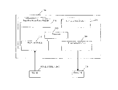
Figure 2 is a block diagram of a Time Division .Duplex ("TDD") modem 108 used
to
modulate/demodulate data in the wireless communication systems 100 described
above. Modems
108 are used by the base station 102 and CPEs 104 to modulate and demodulate
data. For case of
description, the modem 108 will now be described with reference to the base
station 102. One
embodiment .of the modem 108 includes a receiver module 202, a transmitter
module 204, a signal
to noise ratio ("SNR") module 206, and a bit error rate ("BER") module 208. In
another
embodiment, the modem 108. further includes a processor .210. In operation,
the transmitter
module 204 converts digital data to an. appropriately modulated analog signal
communicated as a
downlink 1,10, using :for example, quadrature amplitude modulation ("QAM") or
quadrature phase
shift keying ("QPSK") modulation. The analog signal may also be up converted
to a carrier
frequency prior to transmission. The receiver module 202 demodulates an uplink
112(a), 112(b),
112(c) and converts it back to its original digital, form.
The transmitter module 204 controls the data modulation scheme(s) for the
modem 108.
The transmitter module 204 interfae2s with the SNR module 206. and the .BER
module 208 in
selecting the modulation scheme used to transmit the data. The SNR module 206
can be a
transceiver (not shown) configured to measure the signal to noise ratio of the
received signal.
Alternatively, the SNR module 206 can be a power detector (not shown)
configured to measure the
signal to noise ratio of the received signal. The: SNR can be calculated from
the, bit error rate
determined by the BER module 208.
The processor 210 is configured to monitor signal quality of the received
signal. An
example metric used by the processor to monitoring signal quality is a SNR.
Signal quality is
measured over a, period of time, and, in response to changes in the signal
quality, the processor 210
determines if the modulation should be changed. This helps avoid cyclic
changes in the
-7-
CA 3048205 2019-07-02
modulation scheme due to transient changes in the communication link's
quality. In one
embodiment, only the modem 108 at the base station 102 includes the processor
210. In this
embodiment, each CPE measures its own signal quality and transmits its value
within its uplink
112 to the base station 102. The processor 2:10 is then able to monitor the
signal quality e. f the
CPEs to determine if the downlink 110 modulation schemes should be changed. In
one
embodiment, the processor 210 in the base station 102 monitors its own signal
quality to determine
if the uplink 112 modulation should be changed,
The term "module," as used herein, means, but is not limited to, a software or
hardware
component, such as a FPGA or ASIC, which performs certain tasks. A module may
advantageously be configured to reside on the addressable storage medium and
configured to
execute on one or more processors. Thus, a module may include, by way of
example, components,
such as software components, object-oriented software components, class
components and task
components, processes, functions, attributes, procedures, subroutines,
segments of program code,
drivers, firmware, microcode, circuitry, data, databases, data structures,
tables, arrays, and
variables. The functionality provided for in the components and modules may be
combined into
fewer components and modules or further separated into additional components
and modules.
Additionally; the components and modules may advantageously be implemented to
execute on one
or more computers within the communication system.
FIGURE 3 represents a time division duplexing ("TDB") frame and multi-frame
structure
for use in communication system 100. Frame 300 includes a downlink subframe
302 and an uplink
subframe 304. The downlink subframe 302 is used by the base station 102 to
transmit information
to the plurlaity of CPEs 104(a)-(c). In any given downlink subframe 302, all,
some, or none of the
transmitted information is intended for a specific CPE 104. The base station
102 may transmit the
downlink subframe 302 prior to receiving the uplink subframe 304. The uplink
subframe 304 is
used by the CPEs 104(a)-(c) to transmit information to the base station 102.
Subfrarnes 302, 304 are subdivided into a plurality of physical layer slots
(PS) 306. Each
PS 306 correlates with a duration of time. In the embodiment shown in FIGURE
3, each subframe
302, 304 is one-half millisecond in duration and includes 400 PS for a total
of 800 PS per frame
300. Alternatively, subframes having longer or shorter durations and with more
or fewer PSs can
be used.
Each downlink subframe 302 comprises a frame control header 308 and downlink
data
310. The frame control header 308 includes information for the CPEs to
synchronize with the base
station 102, In one embodiment, the frame control header 308 includes control
information
indicating where modulation changes oCcu, in the downlink. The frame control
header 308 can
also include a map of the subsequent uplink subthme 304 that is to be
transmitted by the CPEs
-8-
CA 3048205 2019-07-02
104. This map allocates the PSs 306 in the uplink subframe 304 between the
different CPEs. The
frame control header 308 can further include a map of attributes of the
downlink data 110. For
example, attributes may include, but are not limited to, the locations of the.
PSs 306 in the subframe
302 that are intended for each individual CPE.
The downlink data 310 is transmitted in a pre-defined modulation or a sequence
of
modulation techniques Ml, M2, M3. Individual or groups of PSs 306 in the
downlink subframe
302 are assigned to data intended for speeific CPEs 104. For .example, the
base station 102 could
assign PSs in one, some, or all of the modulation techniques Ml, M2, M3 for
transmitting data to
CPE 104(a). In Figure 3, the data is divided into three modulations types,
where QPSK (312(a)) is
the most robust modulation (i.e. least prone to transthission errors caused by
signal interference)
and while QAM-64 (312(c)) is the least robust (i.e. most prone to transmission
errors caused by
signal interference). In between these modulation schemes is QAM-32 (312(b)).
In one
embodiment, a sequence such as: QAI4.1-4, followed by QAM-16, followed by QAM-
64 is used. In
other embodiments, additional modulation schemes, such as QAM-256, are used.
Each CPE :104
monitors the downlink data 310 and retains only those messages intended for
them. As mentioned
above, in one embodiment, attributes in the frame control header 308: provide
this information to
the CPEs.
Still referring to Figure 3, the uplink subframe 304 comprises uplink data
314(a)-(n). The
uplink subframe 304 is used by the CPEs 104(a)-(c) to transmit information to
the base station 102.
The subframe 304 is subdivided into a plurality of PSs 306. Each CPE 104(a)-
(c) transmits its
information during its allocated PS 306 or range of PSs 306. In one
embodiment, the PS8 306
allocated for each CPE are grouped into a contiguous blocicof a plurality of
data blocks 314(a)-(n).
In this embodiment, the CPEs use data blocks 314(a)-(n) to transmit the.
uplink subframe 304. The
range of PSs 306 allocated to each block in the plurality of data blocks
314(a)-(ii) is selected by the
base station 102.
The data transmitted in each data block 314(a)-(n) is modulated by the
transmitting CPE.
For example, CPE 104(a) modulates data block 314(a). During its data block,
the CPE transmits
with a fixed modulation that is selected by the base station 102based on
the.SNR and/or BF.R of its
prior transmission(s) to the base station 102. In an alternate embodiment, a
sequence of
modulation techniques is used in each. data block 314(a)-(n).. In still
another embodiment, the data
blocks 314(a),(n) are grouped by modulation scheme. As mentioned above, one
embodiment of
the uplink subframe 304 includes SNR and/or TIER measurements transmitted by
the CPEs for the
base station to use in determining if the modulation of the downlink subframe
302 should be
changed.
-9-
CA 3048205 2019-07-02
Each CPE 104 receives all downlink transmissions that are modulated using its
current
modulation scheme or are modulated using a more robust modulation scheme than
its current
modulation scheme. The frame control header .308 is typically modulated using
the most robust
modulation scheme to ensure that all CPEs 104(a)-(c) may receive it. Because
each CPE receives
the frame control header, each CPE 104 is initially synchronized with the
downlink subframe 302
at the beginning of the frame 300. The downlink subframe is sorted by
robustness, which allows
each CPE to maintain synchronization during the subsequent portion of the
downlink that could
include data. for that CPE. Data that .is modulated using a less robust
modulation scheme than a
CPE's current modulation scheme is not listened to by that CPE. Thus, once
synchronized, each
CPE maintains its connection throughout the portion of the downlink subframe
302 that was
modulated using a modulation scheme that is at least as robust as that CPE's
current scheme_
Since the CPEs are initially synchronized with the downlink subframe, when the
data addressed to
each specific CPE 104 is transmitted the respective CPEs 104 do not need
additional time to
synchronize.
In contrast, the base station 102 receives data from the cpa 104 during
subframe 304
Which requires the base station 102 to synchronize with each individual CPE
104. Synchronization
with each CPE 104 may take &variable amount of PSs 306 to achieve. Thus, the
synchronize time
needed for the base.station 10210 synchronize with multiple CPEs 104(a)-(c)
is. a multiple of each
individual CPE's synchronization activity during the downlink. subframe 302.
As such, the base
station 102 may not be capable of receiving data at the same modulations as
individual CPE's 104.
In some embodiments the base station 102 may be able to receive uplink data at
a higher
modulation than CPEs 104 can receive downlink data.
FIGURE 4 illustrates a graph of four modulation schemes and their respective
upper and
lower modulation thresholds. Specifically, four modulation schemes (M1 - i\44,
where 1\41 is the
most robust and M4 is the least robust), and six modulation thresholds (Ll -
L6, where Li
indicates the lowest, link qtittlity and. L6 indicates the, highest link
quality) arc shown. Lines 414
separate the modulation schemes of Figure 4 and are based on a defined
relationship between link
quality and modulation schemes. In one embodiment, the thresholds Li-L6 are
identical for the
uplink and downlink, such that modulation transition points are the same for
both the uplinlr. and
the downlink. The thresholds are based on measurements of the quality of a
communication link
between a transmitting base station 102 or CPE 104(a)-(c) and a receiving CPE
or base station.
Quality measurements are made for the uplinks 1 12(a)-(c) an.d downlinks
110(a)-(c) in Figure 1.
In one embodiment, the link quality is based on a SNR or BER measurement for
the uplink or
downlink. Alternatively, link quality is determined by measuring the carrier
to noise ration (C/N)
or the ,carrier to noise plus interference ratio (C/(N+I)). For ease of
description, the following
-10-
CA 3048205 2019-07-02
assumes the modulation thresholds for the uplink and downlink are the same.
The following
description would then apply to both the uplink and dOwniiiik. However, in
alternate
embodiments, the modulation thresholds for the uplink and downlink are
different. For example,
the upper and lower thresholds for the uplink 112 may be shifted by a fixed
amount from the
corresponding upper and lower thresholds for the downlink 1.10.
Still referring to Figure 4, modulation schemes M2 and M3 each have a pair of
modulation
thresholds associated thereto. Modulation schemes MI and M4 each have a single
threshold
associated thereto since they are the minimum and maximum modulation schemes
available in the
embodiment of Figure 4. The modulation thresholds include upper thresholds 410
and lower
thresholds 412. In one embodiment, as the downlink/uplink quality exceeds the
upper threshold
410, the modulation scheme is increased. This is accomplished by selecting a
denser and less
robust modulation scheme. Conversely, as. The lower threshold 412 is crossed,
the modulation
scheme is decreased. For example, thresholds Li and L4 are the thresholds for
modulation scheme
M2. If the downlink/uplink quality using M2 falls below L1,. the receiving
base station/CPE will
initiate changing the modulation technique to Ml , Alteniatively, if the
clo.wnlink/uplink quality
using M2 rises above L4, the receiving base station/CPE will initiate changing
the modulation
technique to a higher type, for example, M3. Continuing with this example, if
the modulation is
changed to M3 because the downlink/uplink quality exceeded IA and then the
downlink/uplink
quality decreases below L4, M3 will continue to be used until L3 (the M3 lower
threshold) is
crossed. In other words, in order for a modulation scheme to decrease, the
link quality must
decrease not just to line 414, but to the lower threshold 410 immediately
below line 414. Likewise,
in order for a modulation scheme to increase, the link quality must not only
exceed line 414, but
also must exceed the upper threshold 410 immediately above line 414. By
spacing the upper and
lower thresholds in this manner, the likelihood of rapid changes occurring
between modulation
schemes is decreased.
FIGURE 5 is one embodiment where modulation techniques QAM-256, QAM-64, QAM-
16, and QPSK are selected along with their respective upper and lower
modulation thresholds for
measurements of signal to noise ratios ("SNR"). The modulation thresholds for
QAM-64
transmissions are QAM,64 upper threshold 410(c) and QA1v1-64 lower threshold
412(b). For
example, if a base station 102 is currently downlinking data to a specific CPE
104(a) using QAM-
64 modulation, the modulation scheme will change when the downlink 110(a)
quality goes above
upper threshold 410(c), for example, at 38d13. Likewise, when the. downlink
110(a) quality goes
below lower threshold 412(b), for example, at 12 dB. Furthermore, the
modulation slieme will
not be changed when link quality crosses either QAM-256 lower threshold 412(e)
or QAM-16,
upper threshold 410(b) because they are not current modulation thresholds for
QAM-64. This
-11-
CA 3048205 2019-07-02
limits rapid changes between adjacent modulation schemes caused by small
fluctuations in
downlink quality around an upper or lower threshold.
FIGURES 6a and 6b, illustrate asymmetric adaptive modulation being performed
by the
base station and CPEs from Figure 1 during two different time frames, time
frame A 600 and time
frame B 602. Figures 6a. and 6b illustrate how the uplink and downlink
modulations used by .a base
station 102 and the specific CPEs 104 are asymmetrically ..adaptive. In one
embodiment, time
frame B 602 directly follows time frame A 600. ln another embodiment, time
frame 13 602 occurs
at a later time than time frame A 600.
In time frame A 600, as shown in Figure GA, CPE 104(a) receives downlink
110(a) (see
Figure 1) modulated. at QAM-16 604 from base station 102. CPE 104(a) transmits
uplink 112(c)
(see Figure I) modulated at QPSK 606. Tha qualities for the uplink 112(e) and
downlink 110(a)
may be ,different due to several factors. For example, performing multiple
synchronizations by the,
base station 102 may affect these qualities. Additionally, because multiple
CPE's 104(a)-(c)
typically transmit to base station 102 during a frame 300 (see Figure 3), the
base station may
receive interference between the signals from the multiple CPEs. Additionally,
there may he other
interference sources that only effect data transmission in only one direction.
For example, co-
channel and adjacent channel interference from neighboring cells or sectors
can cause the link
quality for an uplink to be different than the link quality for the downlink.
In subsequent time
frame B 602, the downlink 110(a) modulation scheme from the base station 102
is increased to
QAM-64 614 while the uplink 112(c) modulation scheme from CPE 104(a) remains
at QPSK 606.
This occurs because the quality of the downlink 110(a) has increased beyond an
upper threshold
410(b) (see Figure 5) between time frame A 600 and time frame B 602. The
quality of the uplink
112(t) has not. crossed the QPSK upper threshold 410(a) (see Figure 5), and
thus the uplink 112 (c)
continued using QPSK 606.
Returning to time .franie A 600, CPE 104(b) receives downlink 110(b) (see
Figure 1)
modulated at QAM-64 608 and Uansmits an uplink 112(b) (see Figure .1)
modulated at QAM-16
610. Between time frame A 600 and time frame B 602, the quality for both the
uplink and
downlink crossed over a lower threshold 412(h), 412(a) as evidenced by the
more robust
modulation schemes in time frame 13 602. In time frame B, the downlink 110(b)
is in QA_M-16
618 while uplink is in QPSK 620. Since the modulation sehemes of both links
have decreased, this
may have occurred due to Changes in Weather conditions between the base
station 102 and CPE
104(b).:
Returning once again to time frame A 600, CPE 104(c) receives downlink 110(e)=
(see
Figure 1) modulated at QAM- 16 612 and transmits uplink 112(c) (see Figure 1)
modulated at
QA.M-16 614 to the base station 102. In time frame B 602, both the uplink and
downlink are still
-12-
CA 3048205 2019-07-02
using QA1\4-16 612, 614 modulations. The link qualities of both the uplink
112(c) and downlink
1.10(c) between base station 102 and CPE 104(c) have:not crossed tither an
upper threshold 410(b)
or a lower threshold 412(a).
FIGURE 7 is a flowchart illustrating a process for adaptively adjusting the
downlink
modulation scheme. The base station can adjust its downlink modulation for a
specific CPE 104
independent of that CPE.'s uplink modulation. In one embodiment, the process
is performed during
each frame 300 (one millisecond, for example), or periodically over several
frames (every 10
seconds, for example). The base station 102 performs the process for each CPE
104(a)7(c) within a
sector 106 (see Figure 1). In another embodiment, each CPE determines the
quality of the
downlink. Once determined, the CPE can report the quality information back to
the base station or
determine itself whether the dow-nlink modulation should be adjusted. If the
CPE determines that
the downlink modulation should be adjusted based on its quality measurements,
the CPE sends a
request to the base station to use a different modulation technique. 'The base
station is then able to
adjust its downlink modulation accordingly for the specific =CPE.
in particular, flow begins in start block 700. Flow proceeds to block 702,
where the
quality of the downlink 110 from the base station 102 is determined. The
quality of the downlink
may he a function of. the state of the transmission medium (e.g. air, foggy
air, wet air, smoky air,
etcõ) and the ability of both the transmitting and receiving components (e.g.
base station 102 and
CPE. 104) to respectively transmit and receive data. In one embodiment, each
CPE 1.04(a)-(c)
determines the quality of its respective downlink 110(a)-(c), In another
embodiment; the quality of
the downlink 110 is determined by only one CPE 104. In this embodiment, the
selected CPE 104
can be geographically located near the other CPEs 104 that receive the
downlink 110 using the
same modulation scheme. Jr. still another embodiment, the CPEs 104
periodically transmits
measurements, which are indicative of the quality of their respective downlink
110, to the. base
95 station 102. The base station 102 then uses these measurements to
determine the quality of its.
downlink. These. measurements can include SNR 'and/or HER measurements of the
downlink
110(a)-(c). For example, CPE 104(a) determines the quality of its downlink
110(a) based on a
measurement by its BER module 208 (see Figure :2). A single HER measurement or
a series of
several BER measurements taken by the CPE during a frame 300 (see Figure 3) or
during multiple
frames may be used to determine the downlink quality. In embodiments where the
CPE include a
processor 210 (see Figure 2), multiple measurements are analyzed by the
processor 210 to
determine the downlink's quality. For example, HER measurements may be
averaged over N
frames 300 to generate the downlink quality measurement. In one embodiment,
CPE 104(a)
transmits its measurements to the base station 102 for analysis by a processor
210 in the base
station. The base station then determines the quality of the downlink for CPE
104(a).
-13-
CA 3048205 2019-07-02
Continuing to block 704, the base station or CPE compares the calculated
downlink quality
with the current modulation thresholds, as shown in Figures 4 and 5. The.
current modulation
thresholds are an upper threshold 410 and a lower threshold 412 at which the
modulation scheme is
changed. With reference to Figure 5, the current modulation thresholds for a
QAM-44
transmission are QAM-64 upper threshold 410(c) and QAM-64 lower threshold
412(b). For
example, if the base station 102 is currnntly downlinking data to CPE 104(b)
using QAM-64
modulation, the modulation scheme will change when the uplink quality exceeds
the upper
threshold 410(e) at 38dB or goes below lower threshold 412(b) at 12 dB.
Furthermore, the
modulation.scheme will not be changed when link quality crosses either QAM-256
lower threshold
412(c) or QAM-16 upper threshold 410(b) because they are not current
modulation thresholds.
Next at decision block 706, the base station determines Whether the downlink
quality has
decreased and crossed a modulation lower threshold 412 (see Figure 4)
according to the
comparisons made in block 704. With reference to Figure 5, when the modulation
is QAM-256 the
current modulation lower threshold 412(c) is 32dB. For QAM-64, the current
modulation lower
threshold 412(b) is 12dB. For QAM-16, the current modulation lower threshold
412(a) is 3dB. If
the current modulation lower threshold has been crossed, flow proceeds to
block 708 where the
base station selects a more robust modulation. In embodiments where the CPE
determines the
downlink quality and compares it to the modulation threshold, the CPE 104 can
send a request to
the base station 1:02 indicating a 'desired downlink modulation change. This
request is sent during,
the uplink subframc. Once received by the base station 102, a downlink
modulation change
confirmation is transmitted to the CPE 104 indicating in which frame 300, the
change will occur,
in another embodiment; a confirmation message is not transmitted to the CPE
104, but instead the
CPE. 104 listens for its data at both the current modulation and the
requested, more robust,
modulation. Because the 'CFEs 104 receive all data transmitted by the base
station 102, a change'
in modulation will be evident to a specific CPE 104 when data is received in
the requested
modulation scheme, Flow then returns to block 702.
Returning to decision block 706, if a current modulation lower threshold has
not been
crossed, flow proceeds to decision block 710 where the base station determines
whether the
downlink quality has crossed an upper modulation threshold 410. With reference
to Figure. 5,
when the current modulation is QAM-64 the current modulation upper threshold
410(c) is 38dB.
For QAM-16, the current modulation upper threshold 410(h) is 17dB. For QPSK,
the current
modulation upper threshold 410(a) is 5c1B. If the base station determines that
the current
modulation upper threshold has been exceeded, flow continues to block 712
where the modulation
scheme is changed to a less robust, denser modulation. In embodiments where
the CPE determines
the downlink quality and compares it to the modulation threshold, the CPE 104
sends a request to
-14-
CA 3048205 2019-07-02
the base station 102 indicating a desired downlink modulation change. Once
received by the base
station 102, a downlink modulation change confirmation is transmitted to the
CPE 104 indicating
in which frame 300 the change will occur. In another embodiment, a
confirmation message is not
transmitted to the CPE 104, but instead the CPE 104 listens for its data at
both the current
modulation and the requested, more robust, modulation.. Because the. CPEs 104
receive all data
transmitted by the base station 102, a change in modulation will be evident to
a specific CPE 104
when data is received in the requested modulation scheme. Flow then returns to
block 702.
Returning to deeision block 710, if the downlink quality has not _exceeded the
upper
modulation threshold di.% flow proceeds to block 702.
FIGIURE.8 is a flowchart illustrating the process of adaptively adjusting
uplink modulation
scheme. A specific CPE's 104 can change its uplink modulation independent of
that CPE's 110
downlink modulation. The specific CPE's modulation can also be. independent of
the uplink
modulation schemes used by other CPEs 104 within the same sector .106.
.Because the base station
102 must synchronize with each individual CPE 104 that uplinks data, the
uplink quality may be
different than the downlink quality with a specific CPE 104. In one embodiment
the base station
102 performs the process to adaptively adjust the uplink modulation scheme
used by a specific
CPE 104. As such, a similar process may be completed for each CPE 104 within
the sector 106 in
order to adaptively adjust each CPEs 104 uplink modulation.
In particular, flow begins in start block .800. Flow proceeds to block 802,
where .the
quality of the uplink 112 from a CPF 104 to a base .station 102 is determined.
The quality of the
uplink may be a function of the state of the transmission medium (e.g. air,
foggy air, wet air,
smoky air,. etc.) and the ability of 'both the transmitting and receiving
components (e.g. CPE 104
and base station 102) to respectively transmit and receive data. In one
embodiment, the base
station 102 determines the quality .of each uplink I 12(a)-(c). In another
embodiment, the base
station 102 periodically transmits measurements, which .are indicative. of the
quality of a CPE's
uplink 112, to that CPE 104. The CPE 104 then uses these measurements to
determine the quality
of its uplink. These measurements can include SNR and/or BER measurements of
the uplink
112(a)-(e). For example, base station 1.02 can determine the quality of uplink
112(e) based. on a.
measurement by i.t SNR module 206 (see Figure 2). A single SNR measurement or
a series of
several SNR measurements taken during .a frame 300 (see Figure)) or during.
multiple frames.may
be used to determine the uplink qUality.. In embodiments which include a
processor 210 (see
:Figure 2), multiple measurements are analyzed by the processor 210 to
determine the uplink's
quality. For example, SNR measurements may be averaged over N frames 300 to
generate the
uplink quality measurement. In one embodiment,. base station 102 transmits its
measurements to a
3.5 CPE 104 for analysis by a processor 210. The CPE 104 then.determines
the quality of its uptiL'ik.
=15
CA 3048205 2019-07-02
Continuing to block 804, the base station or CPE compares the calculated
uplink quality
with the current modulation thresholds, as shown in Figures 4 and 5. The
current modulation
thresholds are art upper threshold 410 and a lower threshold 412 at which the
modulation scheme is
changed. With reference to Figure 5, the current modulation thresholds far a
CAIVI.-64
transmission are QAM-64 upper threshold 410(c) and QAM-64 lower threshold
412(b). For
example, if CPE 104(a) is currently uplinking data to base station 102 using
QA1v1-64 modulation,
the modulation scheme will change when the uplink quality exceeds the upper
threshold 410(e) at
38dB or goes below lower threshold 412(b) at 12 dn. Furthermore, the
modulation scheme will
not be changed when link quality crosses .either QA.M-256 lower threshold
412(e) or QAM-16
upper threshold 410(b) because they are notourrent modulation thresholds.
Next at decision block 806, the CPE determines whether the uplink quality has
decreased
and crossed a modulation lower threshold 412 (see Figure 4) according to the
comparison made in
block 804. With reference to. Figure 5, when the modulation is CAM-256 the
current modulation
lower threshold 412(e) is 32dB. For QAM,64, the current modulation lower
threshold 412(b) is
12dB, For CAM-16, the current modulation lower threshold 412(a) is 3dB. If the
current
modulation lower threshold has been crossed, flow proceeds to block 808 where
a less robust
modulation is selected. In embodiments where the base station determines
whether the uplink
quality has crossed the threshold, the base. station 102 can send a request to
the CPE 104 indicating
a desired uplink modulation change. Alternatively, the base station 102 can
transit an uplink map
to all CPEs 104 in the downlink subframe 302 indicating which CPEs have been
allotted uplink
PS's and The PS's associated modulations, This allows the base station 102 to
indicate to an
individual CPE 104 that the modulation scheme has been changed by allotting
uplink subframe 304
PSs to that CPE that uses a more robust modulation scheme, For example, if the
uplink
modulation for CPE 104(a) is to be changed from CAM-64 to 6, the
base station 102
assigns uplink subframe PS's which are to be modulated using CAM-16. This
uplink assignment
serves as an indicator to the cn that its uplink modulation scheme has been
change. Flow then
returns to block 602.
Returning to decision block 806, if a current modulation lower threshold has
not been
crossed, flow proceeds to decision block 810 Where the system determines
whether the uplink
quality has crossed an upper modulation threshold 410. With reference to
Figure 5, when the
current. modulation is CAM-64 the current modulation upper threshold 410(c) is
381:113. For QAM-.
16, the current modulation upper threshold 410(h) is 17d13. For QPSK, the
current modulation
upper threshold 410(a) is 5d13. If the current modulation upper threshold has
been exceeded, flow
continues to block 812 where the modulation scheme is changed to a less
robust, denser
modulation. In one embodiment, the base station 102 sends a request to the CPE
104 indicating a
CA 3048205 2019-07-02
desired uplink modulation change. In another embodiment, the base station 102
transmits an
uplink map to all CPEs 104 in the downlink subframe 302 indicating which CPEs
have been
allotted uplink PS's and the PS's associated modulations. The base station 102
indicates to an
individual CPE 104 that the modulation scheme has been changed by allotting
uplink subframe 304
PSs to that CPE that uses a less robust modulation scheme. For example, if the
uplink modulation
for CPE 104(a) is to be changed from. QAM-16 to QAM-64, the base station 102
assigns uplink
subframe PS's which arc to be modulated using QAM-64. This uplink assignment
serves as an
indicator to the CPE that its uplink modulation scheme has been change. Flow
then returns to
block 802.
Returning to decision block 810, if the dOwnlink quality has not exceeded the
upper
modulation threshold 610, flow proceeds to block 802.
The. foregoing description details certain embodiments of the invention. It
will be
appreciated, however, that no matter how detailed the foregoing appears in
text, the invention can be
practiced in .many ways. As is also stated above, it should be noted that the
use of particular
terminology when describing certain features or aspects of the embodiments
should not be taken to
imply that the terminology is being re-defined herein to be restricted to
including any specific
characteristics of the features or aspects of the embodiment with which that
terminology is associated.
The scope of the.embodiments should thecefore be construed in accordance with
the appended claims
and any equivalents thereof,
-17-
CA 3048205 2019-07-02