Note : Les descriptions sont présentées dans la langue officielle dans laquelle elles ont été soumises.
CA 03048622 2019-06-26
WO 2018/125781
PCT/US2017/068102
DOWNHOLE BLOWER SYSTEM WITH PASSIVE RADIAL BEARINGS
CLAIM OF PRIORITY
[0001] This application claims priority to U.S. Patent Application No.
15/392,258 filed
on December 28, 2016, the entire contents of which are hereby incorporated by
reference.
BACKGROUND
[0002] Most wells behave characteristically different over time, as well as
seasonally,
due to geophysical, physical, and chemical changes in the subterranean
reservoir that
feeds the well. For example, it is common for well production to decline as
the well
to reaches the end of its life. This decline in production is due to
declining pressures in the
reservoir, and can eventually reach a point where there is not enough pressure
in the
reservoir to push production through the well to the surface. In gas wells, a
top side
compressor is sometimes used to extend the life of the well by decreasing
pressure at
the top of the well. This decrease in pressure decreases the pressure head on
the
production flowing to the surface, enabling the well to continue producing
when the
reservoir pressures have dropped too low to drive the production to the
surface.
SUMMARY
[0003] This disclosure describes boosting well production.
[0004] Certain aspects of the subject matter described here can be implemented
as a
downhole-type blower system. A blower can be positioned in a wellbore. The
blower
rotatably drives or is driven by a fluid produced through the wellbore. An
electric
machine can be positioned downhole of the blower, the electric machine
configured to
rotatably drive or be driven by the blower. A bearing shaft couples the blower
and the
electric machine. The bearing shaft transfers rotation between the blower and
the electric
machine. A passive magnetic radial bearing assembly magnetically supports the
bearing
shaft.
[0005] The bearings shaft is made from a non-magnetic material. The bearing
shaft
includes a shaft magnet assembly that includes multiple axially-magnetized
magnets.
The multiple axially-magnetized magnets are radially imbedded into the bearing
shaft.
The multiple axially-magnetized magnets are arranged so that magnet polarities
CA 03048622 2019-06-26
WO 2018/125781
PCT/US2017/068102
alternate along an axis of the bearing shaft. An exterior surface the shaft
magnet
assembly is substantially flush with an outer surface of the bearing shaft. A
stator magnet
assembly surrounds the bearing shaft. The stator magnet assembly includes
multiple
stator magnets. Identical poles of the multiple stator magnets and the
multiple axially-
magnetized magnets are substantially in line with one another.
[0006] The multiple stator magnets are separated from each other by a first
set of
multiple spacers. The multiple axially-magnetized magnets are separated from
each
other by a second set of multiple spacers. The first plurality of spacers and
the second
plurality of spacers are non-magnetic and electrically non-conductive. The
plurality of
stator magnets and the plurality of axially-magnetized magnets are axially
offset from
each other.
[0007] The passive magnetic radial bearing assembly is a first passive
magnetic radial
bearing assembly. The downhole-type blower system also includes a plurality of
passive
magnetic radial bearing assemblies that magnetically support the bearing
shaft. The
multiple passive magnetic radial bearing assemblies include the first passive
mag radial
bearing assembly.
[0008] An active damper is coupled to the bearing shaft. The damper can damp a
vibration of the bearing shaft responsive to transferring the rotation between
the blower
and the electric machine. The active damper assembly includes a damper magnet
coupled to the bearing shaft. The damper magnet is positioned between the
plurality of
radial bearing assemblies. The vibration of the bearing shaft induces an
induced
vibration in the damper magnet. A first damper magnet pole shoe and a second
damper
magnet pole shoe are coupled to a first pole and a second pole, respectively
of the
damper magnet. The first damper magnet pole shoe and the second damper magnet
pole
shoe maintain uniformity of magnetic fields generated by the damper magnet. A
damper
sleeve is positioned over the outer diameters of the damper magnet, the first
damper
magnet pole shoe, and the second damper magnet pole shoe. Multiple radial
velocity
sensing coils are placed in a plane adjacent to the first damper magnet pole
shoe and
coupled to a first pole of the damper magnet. The multiple radial velocity
sensing coils
are exposed to a magnetic field emanated from the first pole of the damper
magnet. A
radial movement of the damper magnet induces an electrical voltage in the
multiple
radial velocity sensing coils. The damper magnet is a first damper magnet
facing the
2
CA 03048622 2019-06-26
WO 2018/125781
PCT/US2017/068102
multiple radial velocity sensing coils with the first pole. The system further
includes a
second damper sensing magnet positioned axially opposite the multiple radial
velocity
sensing coils and oriented to face the plurality of radial velocity sensing
coils with a pole
opposite the first pole. Multiple radial damper actuator coils are placed in a
second plane
.. adjacent to the second damper magnet pole shoe and coupled to a second pole
of the
damper magnet. the multiple radial damper actuator coils are exposed to a
magnetic field
emanated from the second pole of the damper magnet. An electrical current in
the
multiple radial damper actuator coils causes a force to be exerted on the
damper magnet.
The damper magnet is a first damper magnet facing the multiple radial damper
actuator
to coils with the second pole, and wherein the system further comprises a
second damper
sensing magnet positioned on axially opposite the plurality of radial damper
actuator
coils and oriented to face the multiple radial damper actuator coils with a
pole opposite
the second pole. A first printed circuit board (PCB) can include the multiple
radial
velocity sensing coils. A second printed circuit board (PCB) can include the
multiple
radial damper actuator coils.
[0009] Certain aspects of the subject matter described here can be implemented
as a
method. a shaft is centrally positioned within a downhole-type blower system
that
includes a blower and an electric machine with a passive magnetic bearing
assemblies
coupled to the shaft and the downhole-type blower system. The shaft is rotated
within
the downhole-type blower system positioned within a wellbore. The shaft is
axially pre-
loaded towards a thrust bearing assembly attached to a downhole end of the
shaft. The
thrust bearing assembly can support the pre-loading.
[0010] Certain aspects of the subject matter described here can be implemented
as a
downhole-type compressor system. A compressor can be positioned in a wellbore.
The
compressor rotatably drives a fluid produced through the wellbore. An electric
machine
can be positioned downhole of the compressor. The electric machine rotatably
drives
the compressor. A bearing shaft couples the compressor and the electric
machine. The
bearing shaft transfers rotation between the compressor and the electric
machine. A
passive magnetic radial bearing assembly magnetically supports the bearing
shaft. An
.. active electronic damper assembly is coupled to the bearing shaft. The
damper assembly
can damp a vibration of the bearing shaft responsive to transferring the
rotation between
the compressor and the electric machine.
3
CA 03048622 2019-06-26
WO 2018/125781
PCT/US2017/068102
The details of one or more implementations of the subject matter described in
this
specification are set forth in the accompanying drawings and the description
below.
Other features, aspects, and advantages of the subject matter will become
apparent from
the description, the drawings, and the claims.
BRIEF DESCRIPTION OF DRAWINGS
[0011] FIG. 1 is a schematic side view of an example well system including a
downhole
blower.
[0012] FIGS. 2A and 2B are partial side views of example downhole-type blower
systems in a wellbore.
[0013] FIG. 3A is a schematic side view of an example well system including
multiple
downhole blowers.
[0014] FIG. 3B is a flowchart of an example process for monitoring
characteristics of a
blower system.
[0015] FIG. 4 is a schematic diagram of a system for maintaining substantially
equal
pressures across multiple wellbores in a well system.
[0016] FIG. 5 is a flowchart of an example of a process implemented across the
multiple
wellbores in the well system.
[0017] FIG. 6 is a flowchart of an example of a process implemented across two
wellbores.
[0018] FIG. 7 is a schematic diagram of a lateral cross-section of a downhole-
type
blower system.
[0019] FIG. 8 is a schematic diagram of a lateral cross-section of a downhole-
type
blower system blower section.
[0020] FIG. 9A is a detailed view of a seal assembly.
[0021] FIG. 9B is a detailed view of an alternative seal assembly.
[0022] FIG. 10 is a schematic diagram of a seal-less bearing assembly.
[0023] FIG. 11A is a lateral cross-sectional view of a pin bearing assembly.
[0024] FIG. 11B is a lateral cross-sectional view of an alternative pin
bearing assembly.
4
CA 03048622 2019-06-26
WO 2018/125781
PCT/US2017/068102
[0025] FIG. 11C is a lateral cross-sectional view of a lubrication reservoir.
[0026] FIG. 11D is a lateral cross-sectional view of an alternative
lubrication reservoir.
[0027] FIG. 12A is a schematic diagram of a detailed lateral cross-sectional
view of an
electric machine.
[0028] FIG. 12B is a schematic diagram of a detailed lateral cross-sectional
view of a
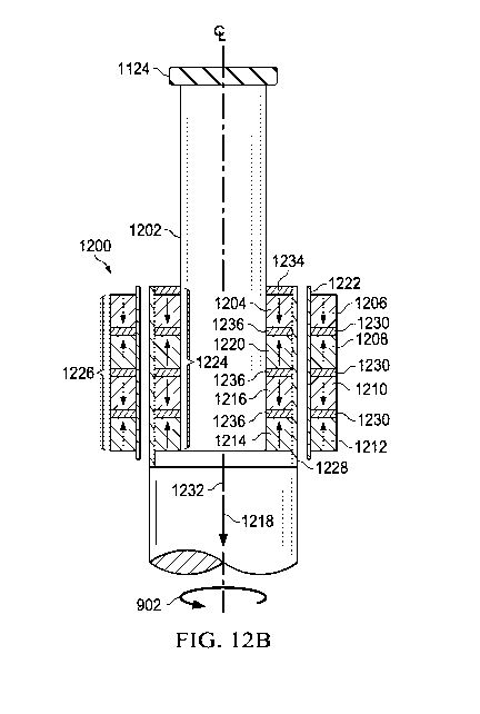
passive magnetic bearing assembly.
[0029] FIGS. 13A-13D are schematic diagrams of active dampers.
[0030] FIG. 14A is a schematic diagram of an electronic damping assembly.
[0031] FIG. 14B is a schematic diagram of an electronic damping assembly.
io [0032] FIG. 15A is a schematic diagram of a top-view of a printed
circuit board.
[0033] FIG. 15B is a schematic diagram of a side-view of a printed circuit
board.
[0034] FIG. 16 is a flowchart showing an example method for utilizing a shaft
supported
with passive magnetic bearings.
[0035] FIG. 17 is a schematic diagram of a lateral cross-section of a downhole-
type
blower system with a single shaft.
[0036] FIG. 18 is a schematic diagram of an integrated blower system.
[0037] FIG. 19 is a schematic diagram of a stator which includes multiple
stator sub-
assemblies.
[0038] FIG. 20 is a schematic diagram of a rotor which includes multiple vane
sections.
[0039] FIG. 21 is a schematic diagram of a cross-section showing multiple
stators and
multiple rotors.
[0040] FIG. 22 is a flowchart of an example of a process for operating an
integrated
blower system.
[0041] FIG. 23A is a schematic diagram of a wellbore in which a blower system
is
disposed downhole.
[0042] FIG. 23B is a schematic diagram of the wellbore in which the seal has
been
energized in response to receiving power from the electromagnetic actuator.
5
CA 03048622 2019-06-26
WO 2018/125781
PCT/US2017/068102
[0043] FIG. 24 is a schematic diagram of the blower system, the seal assembly
and the
electromagnetic actuator being deployed in the wellbore.
[0044] FIG. 25 is a schematic diagram of the blower system, the seal assembly
and the
electromagnetic actuator being deployed in the wellbore.
[0045] FIG. 26 is a schematic diagram of a cross-sectional view of the sucker
rod
carrying the sub-assembly.
[0046] FIG. 27 is a schematic diagram of a seal being deployed using brake
shoes.
[0047] FIG. 28 is a schematic diagram of the seal being deployed using other
techniques.
[0048] FIG. 29A and FIG. 29B are schematic diagrams of a seal being deployed
using
other techniques.
[0049] FIG. 30 is a schematic diagram of the wellbore in which an uphole
blower system
is disposed uphole of the downhole blower system.
[0050] FIG. 31 is a flowchart of an example of a process for deploying a seal
.. surrounding a downhole blower system.
[0051] Like reference symbols in the various drawings indicate like elements.
DETAILED DESCRIPTION
[0052] FIG. 1 depicts an example well system 100 constructed in accordance
with the
concepts herein. The well system 100 includes a well 102 having a wellbore 104
that
extends from the terranean surface 106 through the earth 108 to one more
subterranean
zones of interest 110 (one shown). The well system 100 enables access to the
subterranean zones of interest 110 to allow recovery, i.e., production, of
fluids to the
surface 106 and, in certain instances, additionally or alternatively allows
fluids to be
placed in the earth 108. In certain instances, the subterranean zone 110 is a
formation
within the Earth defining a reservoir, but in other instances, the zone 110
can be multiple
formations or a portion of a formation. For simplicity sake, the well 102 is
shown as a
vertical well with a vertical wellbore 104, but in other instances, the well
102 could be
a deviated well with the wellbore 104 deviated from vertical (e.g., horizontal
or slanted)
and/or the wellbore 104 could be one of the multiple bores of a multilateral
well (i.e., a
.. well having multiple lateral wells branching off another well or wells).
6
CA 03048622 2019-06-26
WO 2018/125781
PCT/US2017/068102
[0053] In certain instances, the well system 100 is a gas well that is used in
producing
natural gas from the subterranean zones of interest 110 to the surface 106.
While termed
a "gas well," the well need not produce only dry gas, and may incidentally or
in much
smaller quantities, produce liquid including oil and/or water. In certain
instances, the
production from the well 102 can be multiphase in any ratio, and/or despite
being a gas
well, the well can produce mostly or entirely liquid at certain times and
mostly or
entirely gas at other times. For example, in certain types of wells it is
common to
produce water for a period of time to gain access to the gas in the
subterranean zone.
The concepts herein, though, are not limited in applicability to gas wells or
even
to production wells, and could be used in wells for producing liquid
resources such as oil,
water or other liquid resource, and/or could be used in injection wells,
disposal wells or
other types of wells used in placing fluids into the Earth.
[0054] The wellbore 104 is typically, although not necessarily, cylindrical.
All or a
portion of the wellbore 104 is lined with a tubing, i.e., casing 112. The
casing 112
connects with a wellhead 118 at the terranean surface 106 and extends downward
into
the wellbore 104. The casing 112 operates to isolate the bore of the well 102,
defined in
the cased portion of the well 102 by the inner bore 116 of the casing 112,
from the
surrounding earth 108. The casing 112 can be formed of a single continuous
tubing or
multiple lengths of tubing joined (e.g., threadingly and/or otherwise) end-to-
end. In FIG.
1, the casing 112 is perforated (i.e., having perforations 114) in the
subterranean zone
of interest 110 to allow fluid communication between the subterranean zone of
interest
110 and the bore 116 of the casing 112. In other instances, the casing 112 is
omitted or
ceases in the region of the subterranean zone of interest 110. This portion of
the wellbore
104 without casing is often referred to as "open hole."
[0055] The wellhead 118 defines an attachment point for other equipment of the
well
system 100 to be attached to the well 102. For example, FIG. 1 shows well 102
being
produced with a Christmas tree 120 attached the wellhead 118. The Christmas
tree 120
includes valves used to regulate flow into or out of the well 102.
[0056] FIG. 1 shows a surface compressor 122 residing on the terranean surface
106
and fluidly coupled to the well 102 through the Christmas tree 120. The
surface
compressor 122 can include a variable speed or fixed speed compressor. The
well system
100 also includes a downhole-type blower system 124 residing in the wellbore
104, for
7
CA 03048622 2019-06-26
WO 2018/125781
PCT/US2017/068102
example, at a depth that is nearer to subterranean zone 110 than the terranean
surface
106. The surface compressor 122 operates to draw down the pressure inside the
well 102
at the surface 106 to facilitate production of fluids to the surface 106 and
out of the well
102. The downhole blower system 124, being of a type configured in size and
robust
.. construction for installation within a well 102, assists by creating an
additional pressure
differential within the well 102. In particular, casing 112 is commercially
produced in
a number of common sizes specified by the American Petroleum Institute (the
"API),
including 4-1/2, 5, 5-1/2, 6, 6-5/8, 7, 7-5/8, 16/8, 9-5/8, 10-3/4, 11-3/4, 13-
3/8, 16, 116/8
and 20 inches, and the API specifies internal diameters for each casing size.
The
downhole blower system 124 can be configured to fit in, and (as discussed in
more detail
below) in certain instances, seal to the inner diameter of one of the
specified API casing
sizes. Of course, the downhole blower system 124 can be made to fit in and, in
certain
instances, seal to other sizes of casing or tubing or otherwise seal to the
wall of the
wellbore 104.
[0057] Additionally, as a downhole type blower system 124, the construction of
its
components are configured to withstand the impacts, scraping, and other
physical
challenges the blower system 124 will encounter while being passed hundreds of
feet/meters or even multiple miles/kilometers into and out of the wellbore
104. For
example, the downhole-type blower system 124 can be disposed in the wellbore
104 at
a depth of up to 15,000 feet (4572 meters). Beyond just a rugged exterior,
this
encompasses having certain portions of any electronics being ruggedized to be
shock
resistant and remain fluid tight during such physical challenges and during
operation.
Additionally, the downhole blower system 124 is configured to withstand and
operate
for extended periods of time (e.g., multiple weeks, months or years) at the
pressures and
temperatures experienced in the wellbore 104, which temperatures can exceed
400 F /
205 C. Finally, as a downhole type blower system 124, the blower system 124
can be
configured to interface with one or more of the common deployment systems,
such as
jointed tubing (i.e., lengths of tubing joined end-to-end, threadingly and/or
otherwise),
coiled tubing (i.e., not-jointed tubing, but rather a continuous, unbroken and
flexible
.. tubing formed as a single piece of material), or wireline with an
electrical conductor
(i.e., a monofilament or multifilament wire rope with one or more electrical
conductors,
sometimes called e-line) and thus have a corresponding connector (e.g.,
positioning
connector 728 discussed below, which can be a jointed tubing connector, coiled
tubing
8
CA 03048622 2019-06-26
WO 2018/125781
PCT/US2017/068102
connector, or wireline connector). In FIG. 1, the blower system 124 is shown
deployed
on wireline 128.
[0058] A seal system 126 integrated with the downhole-type blower system 124,
as
shown, or provided separately, divides the well 102 into an uphole zone 130
above the
seal system 126 and a downhole zone 132 below the seal system 126. FIG. 1
shows the
downhole-type blower system 124 positioned in the open volume of the bore 116
of the
casing 112, and not within or a part of another string of tubing in the well
102. The wall
of the wellbore 104 includes the interior wall of the casing 112 in portions
of the
wellbore 104 having the casing 112, and includes the open hole wellbore wall
in uncased
portions of the wellbore 104. Thus, the seal system 126 is configured to seal
against the
wall of the wellbore 104, for example, against the interior wall of the casing
112 in the
cased portions of the wellbore 104 or against the interior wall of the
wellbore 104 in the
uncased, open hole portions of the wellbore 104. In certain instances, the
seal system
126 can form a gas tight seal at the pressure differential the blower system
124 creates
in the well 102. In some instances, the seal system 126 of the downhole-type
blower
system 124 seals against the interior wall of the casing 112 or the open hole
portion of
the wellbore 104. For example, the seal system 126 can be configured to at
least partially
seal against an interior wall of the wellbore 104 to separate (completely or
substantially)
a pressure in the wellbore 104 downhole of the seal system 126 of the downhole-
type
blower system 124 from a pressure in the wellbore 104 uphole of the seal
system 126 of
the downhole-type blower system 124. Although FIG. 1 includes both the surface
compressor 122 and the blower system 124, in other instances, the surface
compressor
122 can be omitted and the blower system 124 can provide the entire pressure
boost in
the well 102.
[0059] In some implementations, the downhole type blower system 124 can be
implemented to alter characteristics of a wellbore by a mechanical
intervention at the
source. Alternatively or in addition to any of the other implementations
described in
this specification, the downhole type blower system 124 can be implemented as
a high
flow, low pressure rotary device for gas flow in sub-atmospheric wells.
Alternatively
or in addition to any of the other implementations described in this
specification, the
downhole type blower system 124 can be implemented in a direct well-casing
deployment for production through the wellbore.
9
CA 03048622 2019-06-26
WO 2018/125781
PCT/US2017/068102
[0060] The downhole blower system 124 locally alters the pressure,
temperature, and/or
flow rate conditions of the gas in the wellbore 104 proximate the blower
system 124
(e.g., at the base of the wellbore 104). In certain instances, the alteration
performed by
the blower system 124 can optimize or help in optimizing gas flow through the
wellbore
104. As described above, the downhole-type blower system 124 creates a
pressure
differential within the well 102, for example, particularly within the
wellbore 104 the
blower system 124 resides in. In some instances, a pressure at the base of the
wellbore
104 is a low pressure (e.g., sub-atmospheric); so unassisted gas flow in the
wellbore can
be slow or stagnant. In these and other instances, the downhole-type blower
system 124
introduced to the wellbore 104 adjacent the perforations 114 can reduce the
pressure in
the wellbore 104 near the perforations 114 to induce greater gas flow from the
subterranean zone 110, increase a temperature of the gas entering the blower
system 124
to reduce condensation from limiting production, and increase a pressure in
the wellbore
104 uphole of the blower system 124 to increase gas flow to the surface 106.
[0061] The blower system 124 moves the gas at a first pressure downhole of the
blower
to a second, higher pressure uphole of the blower system 124. The blower
system 124
can operate at and maintain a pressure ratio across the blower system 124
between the
second, higher uphole pressure and the first, downhole pressure in the
wellbore. The
pressure ratio of the second pressure to the first pressure can also vary, for
example,
.. based on an operating speed of the blower system 124, as described in more
detail below.
In some instances, the pressure ratio across the blower system 124 is less
than 2:1, where
a pressure of the gas uphole of the blower system 124 (i.e., the second,
higher pressure)
is at or below twice the pressure of the gas downhole of the blower system 124
(i.e., the
first pressure). For example, the pressure ratio across the blower system 124
can be
about 1.125:1, 1.5:1, 1.75:1, 2:1, or another pressure ratio between 1:1 and
2:1. In
certain instances, the blower system 124 is configured to operate at a
pressure ratio of
greater than 2:1.
[0062] The downhole-type blower system 124 can operate in a variety of
downhole
conditions of the wellbore 104. For example, the initial pressure within the
wellbore
104 can vary based on the type of well, depth of the well 102, production flow
from the
perforations into the wellbore 104, and/or other factors. In some examples,
the pressure
in the wellbore 104 proximate a bottomhole location is sub-atmospheric, where
the
CA 03048622 2019-06-26
WO 2018/125781
PCT/US2017/068102
pressure in the wellbore 104 is at or below about 14.7 pounds per square inch
absolute
(psia), or about 101.3 kiloPascal (kPa). The blower system 124 can operate in
sub-
atmospheric wellbore pressures, for example, at wellbore pressure between 2
psia (13.8
kPa) and 14.7 psia (101.3 kPa).
[0063] The blower system 124 is shown schematically in FIG. 1. FIG. 2A is a
partial
side view of the example blower system 124 disposed in the casing 112 of the
wellbore
104 of FIG. 1. Referring to both FIGS. 1 and 2A, the example blower system 124
includes a blower 200, seal system 202, and an electric machine 204. The
blower 200
includes an inlet 206 to receive a gas at the first pressure downhole of the
blower 200
and an outlet 208 to output the gas at the second, higher pressure uphole of
the blower
200. A blower housing 210 houses an impeller (not shown) in fluid
communication
with the inlet 206 to receive the gas from the wellbore 104 at the first
pressure downhole
of the blower 200 and to direct the gas to the outlet 208 at the second,
higher pressure
uphole of the blower 200. With the blower system 124 residing in the wellbore
104, the
.. inlet 206 is at a downhole end of the blower 200, downhole from the seal
system 202,
and the outlet 208 is at an uphole end of the blower 200 on an opposite side
of the seal
system 202. In some instances, the blower system 124 can be positioned in the
well
with the downhole inlet 206 positioned adjacent to the perforations 114 in the
wellbore
104. For example, the blower 200 can be positioned in the wellbore 104 such
that the
inlet 206 is disposed next to and immediately uphole of the perforations 114
to maximize
or improve the gas flow from the perforations into the blower 200. In some
examples,
the inlet 206 may not be adjacent to perforations 114, such as the inlet 206
being
positioned greater than about twenty feet away from the perforations 114. In
some
instances, a speed of the blower 200 is adjusted based on the gas flow from
the
subterranean zone into the wellbore 104 (e.g., via perforations 114). For
example, as
the gas flow from the subterranean zone into the wellbore 104 decreases, a
speed of the
blower 200 can increase to draw more gas flow from the subterranean zone into
the
wellbore 104.
[0064] The blower system 124 moves the gas from the downhole inlet 206 at the
first
pressure to the uphole outlet 208 at the second, higher pressure. This
pressure
differential promotes the gas flow to move uphole of the blower system 124,
for
example, at a higher flow rate compared to a flow rate in a wellbore without a
downhole-
11
CA 03048622 2019-06-26
WO 2018/125781
PCT/US2017/068102
type blower. The blower 200 can operate at a variety of speeds, for example,
where
operating at higher speeds increases fluid flow, and operating a lower speeds
reduces
fluid flow. For example, the impeller of the blower 200 can operate at speeds
up to
120,000 revolutions per minute (rpm), yet be run at lower speeds (e.g., 40,000
rpm, or
other) for a lower flow based on the well conditions and response. While the
blower
system has an optimal speed range at which it is most efficient, this does not
prevent the
blower system from running at less efficient speeds to achieve a desired flow
for a
particular well.
[0065] The electric machine 204 is connected to the blower 200 to drive the
blower 200.
.. The electric machine 204 can include an electric motor, such as a
sensorless motor, a
synchronous motor, and/or other electric motor type. For example, the electric
motor
can include a permanent magnet motor, a four-pole electric motor, and/or other
electric
motor arrangement. The electric machine 204 can connect to the blower 200 in a
variety
of ways. In some examples, the electric machine 204 can include a direct-drive
electric
motor coupled to a rotor of the blower 200, as described in more detail below,
or the
electric machine 204 and blower 200 can connect without a direct-drive
arrangement.
For example, the electric machine 204 can connect to a rotor of the blower 200
on a
single, unitary shaft, with a shaft-rotor coupling or other 1:1 gear train,
without a
gearbox, or using another arrangement type, as described in more detail below.
In some
.. examples, as explained in more detail below, the electric machine 204 is an
electric
motor and a generator, where the electric machine 204 can operate in an
electric motor
mode to provide energy to a blower or a generator mode to receive energy from
a blower.
Although the electric machine 204 is shown in FIG. 2A as disposed downhole of
the
blower 200, the electric machine 204 can be positioned elsewhere, for example,
uphole
of the blower 200 or integral with the blower 200. The electric machine 204
can include
a motor housing 214 to house the electric machine 204 (e.g., electric motor).
In some
instances, the motor housing 214 surrounds the electric motor of the electric
machine,
and absorbs heat (e.g., excess heat) from the electric motor during operation
of the
electric motor. The motor housing 214 can conduct heat from the electric motor
of the
electric machine 204 to the process gas in the wellbore 104, for example, to
increase a
temperature of the gas in the wellbore 104 close to and in contact with the
motor housing
214. In some examples, the housing 214 is not thermally insulated from a
stator of the
electric motor and/or other heat producing portions of the electric motor. For
example,
12
CA 03048622 2019-06-26
WO 2018/125781
PCT/US2017/068102
the stator can be in conductive heat transfer with the housing 214, and in
some instances,
touching along its entire length or nearly its entire length fins on an
exterior of the
housing 214, where the fins contact the fluid in the wellbore 104. In certain
instances,
the portion of the housing 214 that contacts the fluid is above the motor, so
as heat rises,
it is transferred at least in part to the process fluid in the wellbore 104.
Increasing the
temperature of the gas can decrease a liquid content or condensation of the
process gas
entering the blower 200, reduce or prevent a condensation barrier forming in
the gas
flow path, reduce a condensation of moisture of the gas flow uphole of the
blower system
124, and/or other benefits of increasing the gas temperature proximate the
motor housing
214.
[0066] As shown, the electric machine 204 connects to a power source 216 at
the well
terranean surface 106 via conductor wires (not shown) adjacent to or within
the
conveyance 134 (e.g., wireline 128) extending between the electric machine 204
and the
well surface 106. In some instances, the electric machine 204 includes a power
source
integral to or adjacent to the electric machine 204 to power the electric
machine 204 to
drive the blower 200. For example, the power source can include the generator,
as
described both above and below, and/or a local power source (e.g., battery)
disposed
downhole in the wellbore 104.
[0067] The seal system 202 is like the seal system 126 of FIG. 1, and isolates
(substantially or completely) the first pressure downhole of the blower system
124 from
the second wellbore pressure uphole of the blower system 124. The seal system
202 can
take a variety of forms. FIG. 2A shows the seal system 202 as including
multiple annular
disk seals 212 on an exterior of the blower 200 to engage a wall of the casing
112 or an
open hole wall of the wellbore 104. An outer diameter of the annular disk seal
or seals
212 can be the same (substantially or exactly) or just larger than an inner
diameter of the
interior wall of the wellbore or casing. FIG. 2A shows five disk seals 212,
but a different
number of disk seals 212 can be utilized. For example, the seal system 202 can
include
any number of disk seals 212 (e.g., one, two, four, ten, or any other number
of disk
seals). The disk seals 212 can each be made of the same material, or one or
more of the
disk seals 212 can be a different material. The material of the disk seals 212
can vary,
for example, to maintain the seal with the interior wall of the casing 112 or
wellbore 104
while accounting for a wide range of downhole condition variances, such as
temperature,
13
CA 03048622 2019-06-26
WO 2018/125781
PCT/US2017/068102
pressure, vibration, and/or other variances. In some examples, a first disk
seal includes
a rubber polymer that can seal with an inner wall of the casing 112 or
wellbore 104 while
allowing some flex of the first disk seal. For example, a disk seal material
can include
a soft inert material, such as VitonTM or TeflonTm. A second disk seal can
include leather
or Neoprene rubber. Disk seal materials can vary for compatibility with the
well gas
composition to meet life requirements, durability and survivability for depth
of
deployment, toughness in maintaining material and shape during deployment
and/or
engagement with (e.g., rubbing, sliding, or other) the wall of the wellbore or
casing,
ability to deal with sand and muck on the wall of the wellbore or casing,
and/or
to temperature capability for an install location of the well, to name a
few. The use of
multiple materials allows benefiting characteristics of each material to be
matched with
the well in order to ensure a good seal that can maintain the pressure
differential between
the inlet and the outlet of the blower. Multiple disk seals 212 of different
materials can
strengthen the gas tight seal between the seal system 202 and the inner wall
of the casing
112 or wellbore 104, for example, by including multiple materials that can
respond
differently to varying wellbore conditions. For example, a first disk seal
material can
be selected for maintaining a gas-tight seal at high or low temperatures
better than other
materials, a second disk seal material can be selected for maintaining a gas-
tight seal at
high or low pressures better than other materials, a third disk seal material
can be
selected for maintaining a gas-tight seal at high vibration better than other
materials, and
so on. At least one disk seal can be used for at least one of the variety of
wellbore
environments that the seal system 202 may be exposed to during operation of
the blower
system 124, such as high pressure, low pressure, high temperature, low
temperature,
high vibration, low vibration, and/or other wellbore environments. In some
instances,
the seal system 202 can be different. For example, the seal system 202 can
include an
actuatable annular packer seal configured to engage and seal against the inner
surface of
the wellbore 104, as described in more detail below.
[0068] In the example well system 100 of FIG. 1, the blower system 124 is
supported
in the wellbore 104 at least in part by a blind conveyance 134, which extends
from the
surface of the well 102 to support the blower system 124. The blind conveyance
134
connects to the blower system 124 and supports the blower system 124 within
the
wellbore 104, and excludes a fluid flow pathway for fluid flow. For example,
the blind
conveyance 134 excludes a production tubing that connects an interior of the
production
14
CA 03048622 2019-06-26
WO 2018/125781
PCT/US2017/068102
tubing to a gas flow outlet of the blower system 124. Instead, the blind
conveyance 134
supports the blower system 124 in the wellbore without taking in the gas flow
output
from the blower system 124. For example, the blind conveyance 134 can include
the
common deployment systems discussed above, such as coiled tubing, jointed
tubing, or
wireline 128. In some instances, the blind conveyance 134 includes a seal
passageway
for electrical conductors extending between a surface of the well 102 and the
blower
system 124. In the example well system 100 of FIG. 1, the blind conveyance 134
includes the wireline 128.
[0069] In some instances, as shown in FIG. 2B, the blower system 124 is
supported in
the wellbore 104 at least in part by a solid stop 218 against a wall of the
wellbore 104
or casing 112. FIG. 2B is a partial side view of the example blower system 124
disposed
in the casing 112 of the wellbore 104 of FIG. 1. The blower system 124 of FIG.
2B is
the same as the blower system 124 of FIG. 2A, except that the blower system
124 is
supported in the wellbore 104 by the solid stop 218. The solid stop 218
functions to
support the blower system 124 in the wellbore 104 with or without a conveyance
from
atop surface of the well 102. The solid stop 218 is shown schematically in
FIG. 2B, but
the solid stop 218 can take a variety of forms. For example, the solid stop
218 can
include a collar stop, a shoulder of the blower assembly 124 configured to
engage an
annular seat in the casing 112, a spider configured to engage a wall of the
wellbore 104
.. (e.g., the casing 112 and/or other wall), slips that actuate to grip the
wall of the wellbore
104 (e.g., the casing 112 and/or other wall), and/or another solid stop type.
[0070] The blower system 124 outputs a gas flow uphole of the blower system
124
toward the terranean surface 106 of the well 102. The gas flow is outputted
from the
blower system 124 to be in contact with the inner wall of the wellbore 104
and/or the
inner wall of the casing 104 uphole of the blower system 124. In other words,
the gas
flow exits the blower system 124 to the open bore 116, or an open space of the
wellbore
104 uphole of the blower system 124. The gas is not collected by a separate
conduit
positioned within the wellbore or casing. The blower system 124 boosts the gas
flow
within the wellbore 104 toward the well surface, for example, without
conveying the gas
flow output from the blower system 124 through production tubing or other open
conveyance tubing. Instead, the blower system 124 boosts the gas flow within
the
wellbore 104, where the gas flow remains within the open space of the wellbore
104 and
CA 03048622 2019-06-26
WO 2018/125781
PCT/US2017/068102
in contact with the inner wall of the wellbore 104 or casing 112 as it flows
toward the
terranean surface 106 of the well 102.
[0071] Alternatively or in addition to any of the other implementations
described in this
specification, the downhole type blower system 124 can be implemented for
integrated
control of topside and downhole blowers. FIG. 3A is a schematic side view of
an
example well system 300. The well system 300 is like the well system 100 of
FIG. 1,
except the well system 300 includes a second blower system 302 supported in
the
wellbore 104 on the wireline 128 uphole of the (first) blower system 124. The
second
blower system 302 is positioned in the wellbore 104 between the first blower
system
124 and the surface compressor 122 (e.g., surface blower). In other words, the
first
blower system 124 and the second blower system 302 are disposed in the
wellbore 104
in series. Also, the surface compressor 122 is disposed in series with the
first blower
system 124 and the second blower system 302, with respect to the gas flow. In
a
multilateral well, as described in more detail below, the blower systems can
be arranged
differently, such as in parallel, or a combination of parallel and series
arrangements of
blower systems. The first blower system 124 and the second blower system 302
can
operate separately or simultaneously to boost gas flow in the wellbore 104 to
the
terranean surface 106 of the well 102 and optimize or help in optimizing
production
through the well system 300. Each blower system creates a pressure
differential in the
wellbore 104 by locally altering the fluid flow, fluid pressures, fluid
temperatures,
and/or other characteristics of the fluid flow to optimize or improve the
fluid flow
through the wellbore 104. Although the well system 300 of FIG. 3A shows two
downhole-type blower systems with a surface compressor 122 outside of the
wellbore
104, the well system 300 can include additional blower systems (i.e., three or
more)
disposed within the wellbore 104, and/or can omit the surface compressor 122
so the
one or more blower systems residing in the wellbore 104 provide the entire
pressure
boost in the well 102. In some examples, the blower systems are disposed in
the
wellbore 104 such that a distance between two adjacent blower systems is a
maximum
distance of 16,000 feet (4880 meters) and a minimum distance of two feet (0.6
meters)
apart from one another. However, the distance between the blower systems can
vary.
For example, the distance between the blower systems can be selected based on
an
expected or desired pressure ratio at a downhole location in the wellbore 104.
In some
examples, the distance between blower systems can be selected based on a
pressure head
16
CA 03048622 2019-06-26
WO 2018/125781
PCT/US2017/068102
the blower system or systems expect to overcome, for example, so a lower
blower
system in the wellbore has enough pressure to communicate the fluid flow to an
upper
blower system (i.e., blower system more uphole than the lower blower system).
In the
example well system 300 of FIG. 3A, the first blower system 124 is nearer to
the
perforations 114 through which the production fluid (e.g., gas) enters the
wellbore 104
than the terranean surface 106. The second blower system 302 of the example
well
system 300 can be nearer to the surface 106 than the perforation 114, or
nearer to the
perforations 114 than to the surface 106. However, the locations of the blower
systems
124 and 302 residing in the wellbore 104 can vary, as described above.
[0072] As described above, the first blower system 124 includes a blower, a
seal system,
and an electric machine. The second blower system 302 includes a second
blower, a
second seal system, and a second electric machine electrically connected,
mechanically
connected, or both electrically and mechanically connected to the second
blower. The
second blower system 302 includes an uphole conveyance attachment at an uphole
end
of the second blower system 302 to interface with and attach to the conveyance
134
(e.g., wireline 128), and includes a downhole conveyance attachment at a
downhole end
of the second blower system 302 to interface with and attach to the section of
the
conveyance 134 (e.g., wireline 128) that extends downhole to the first blower
system
124. For example, FIGS. 2A and 2B show a conveyance attachment to the first
blower
system 124 as a wireline attachment; however, the type of attachment can vary
based on
the type of conveyance 134 attaching to the respective blower system. For
example, the
conveyance attachment on the blower systems 124 or 302 can include a connector
for
any type of conveyance (e.g., wireline, coiled tubing, joint tubing,
slickline, or other
conveyance). The second blower system 302 can also include a bypass passageway
to
house the conductor wires that extend from the section of the wireline 128
uphole of the
second blower system 302 through the bypass passageway of the second blower
system
302 to the section of the conveyance 134 (e.g., wireline 128) downhole of the
second
blower system 302. The conductor wires connected to the electric machine of
the first
blower system 124 can bypass the second blower system 302 as the conductor
wires
extend from the terranean surface 106 of the well 102 to the first blower
system 124.
[0073] A controller 304 is communicably coupled to the multiple blower systems
(e.g.,
by wired techniques, wireless techniques, combinations of them or otherwise)
to monitor
17
CA 03048622 2019-06-26
WO 2018/125781
PCT/US2017/068102
characteristics of the gas proximate the blower systems and/or monitor
characteristics
of the blower systems, and adjust an operating parameter of the first blower
system 124,
the second blower system 302, or both blower systems. For example, the
controller 304
can measure a parameter value representative of that parameter (e.g.,
temperature,
pressure, density, flow, current, voltage, speed, and/or other), compare this
measured
parameter value against a stored or recorded value, and make a decision based
on a result
of the comparison. For example, one or more sensors coupled to the blower
systems
124 and 302 can sense various operating parameters of the blower systems and
the
wellbore environment, and transmit signals representing the sensed parameters
to the
controller 304. In some instances, the controller 302 can identify a current
or voltage at
a respective blower system. The controller 304 is configured to receive
signals from the
blower systems 124 and 302 and/or the one or more sensors, and can send
signals to the
blower systems 124 and 302 and/or the one or more sensors. In certain
instances, the
controller 304 is also communicably coupled to the surface compressor 122. The
controller 304 can be implemented as hardware, software, firmware, processing
circuitry, or combinations of these. In some instances, the controller 304 can
include
one or more processors and a computer-readable medium storing instructions
executable
by the one or more processors to perform operations. FIG. 3A shows the
controller at
the terranean surface 10 of the well 102; however, the controller 304 can be
implemented
at or above the terranean surface 10, within the wellbore 104, or integrated
with the first
blower system 124 or second blower system 302.
[0074] FIG. 3B is a flowchart showing an example process 310 for monitoring
characteristics in a wellbore, for example, implemented by the controller 304
in well
system 300. At 312, the controller 304 monitors a first set of characteristics
of the gas
proximate the first blower system 124, and at 314, monitors a second set of
characteristics of the gas proximate the second blower system 302. For
example, the
controller 304 can monitor one or more of pressure, temperature, liquid
content, or flow
rate of gas immediately downhole of or immediately uphole of the first blower
system
124 and/or the second blower system 302. The controller 304 monitors these
characteristics in real time, for example, to account for the dynamic and
changing
environment of the reservoir and/or the subterranean zone of interest 110 and
the gas
entering the wellbore 104 from the reservoir, such as liquid surges, and
sudden drops or
increases in pressure from pockets of gas trapped in cavities of the
reservoir. Monitoring
18
CA 03048622 2019-06-26
WO 2018/125781
PCT/US2017/068102
in real time means that a time interval between a time instant at which one or
more
characteristics are sensed by the blower sensors or one or more sensors and a
time instant
at which the sensed characteristics are transmitted to the controller 304 is
negligible, for
example, less than 1 second or less than 1 microsecond. In some examples,
monitoring
in real time includes a continuous monitoring of a set or sets of
characteristics of the
gas.
[0075] At 316, the controller 304 compares the first set of gas
characteristics with the
second set of gas characteristics to determine an operational state of the
well system
300. For example, by comparing the two sets of gas characteristics, the
controller 304
ensures that either or both of the blower systems 124 and 302 are operating at
an optimal
speed. Based on the comparison of the first set of characteristics with the
second set of
characteristics, and shown at 318, the controller can adjust one or more
operating
parameters (e.g., blower speed) of the first blower system 124, the second
blower system
302, the surface compressor 122, or a combination of these. For example, the
controller
304 can adjust (e.g., increase or decrease) the blower speed of the first
blower system
124 or the second blower system 302 in response to the monitored pressure,
temperature,
or other measured characteristics of the gas flow in the wellbore 104. In
certain
instances, the controller adjusts the speed of the blower of the first blower
system 124
or the second blower system 302 by adjusting a voltage and current to the
electric
machine of the first blower system 124 or the second blower system 302. The
adjustment can include a stepped adjustment until a desired characteristic (or
characteristics) is reached. For example, the adjustment can include a stepped
increase
or decrease in blower speed until a desired input pressure, output pressure,
temperature,
or other characteristic is reached. In some instances, the adjustment can
include a
straight adjustment, for example, increasing a blower speed from a first speed
to a
second, different speed. The controller can make these adjustments in real
time, for
example, immediately in response to changing wellbore conditions, desired
blower
system operation, or other.
[0076] In some examples, monitoring the first set of characteristics and the
second set
of characteristics includes monitoring a first inlet gas pressure at an inlet
of the first
blower, monitoring a first outlet gas pressure at an outlet of the first
blower, monitoring
a second inlet gas pressure at an inlet of the second blower, and monitoring a
second
19
CA 03048622 2019-06-26
WO 2018/125781
PCT/US2017/068102
outlet gas pressure at an outlet of the second blower. Since the first blower
system 124
and the second blower system 302 each create a pressure differential in the
wellbore 104
at their respective downhole locations, the first inlet gas pressure is less
than the first
outlet gas pressure, and the second inlet gas pressure is less than the second
outlet gas
pressure. In FIG. 3A, the second blower system 302 is adjacently uphole of the
first
blower system 124. That is, no blower system is disposed in the wellbore 104
between
the first blower system 124 and the second blower system 302. So, during
operation of
the first blower system 124 and the second blower system 302, the second
outlet gas
pressure (i.e., the gas pressure uphole of the second blower system 302) is
greater than
the first outlet gas pressure (i.e., the gas pressure uphole of the first
blower system 124
and downhole of the second blower system 302). In some examples, the second
outlet
gas pressure is less than or equal to two times the first outlet gas pressure.
[0077] In some instances, the controller 304 determines that the outlet (i.e.,
uphole) gas
pressure of the first blower system 124 and/or the second blower system 302 is
greater
than a respective maximum threshold pressure or less than a respective minimum
threshold pressure. Responsively, the controller 304 adjusts the respective
blower speed
of the first blower system 124 and/or the second blower system 302 to achieve
a desired
pressure in the wellbore 104, for example, between a maximum threshold
pressure and
a minimum threshold pressure. In certain instances, the controller 304
continuously
adjusts an operating parameter of at least one of the first blower system 124
or second
blower system 302 to maintain a pressure ratio across the respective blower
system.
[0078] In certain examples, monitoring the first set of characteristics and
the second set
of characteristics can also include monitoring a first inlet gas temperature
at the inlet of
the first blower, monitoring a first outlet gas temperature at the outlet of
the first blower,
monitoring a second inlet gas temperature at an inlet of the second blower,
and
monitoring a second outlet gas temperature at an outlet of the second blower.
[0079] The controller 304 can control output from each blower system in the
wellbore
104 to effectively maximize or improve wellbore production being delivered to
the
wellhead 118. The controller 304 can independently adjust blower speeds while
.. monitoring pressure, temperature, flow, and other wellbore conditions, and
use the
monitored information to continuously adjust and balance production through
the
wellbore 104. In some instances, the well system 300 includes a variable speed
drive
CA 03048622 2019-06-26
WO 2018/125781
PCT/US2017/068102
(VSD) 306 and/or a variable frequency drive (VFD) 308 to assist the controller
304 in
controlling and adjusting operational parameters of the one or more blower
systems in
the wellbore 104.
[0080] Alternatively or in addition to any of the other implementations
described in this
specification, the downhole type blower system 124 can be implemented to
optimize
production through multiple wellbores in a well system. To do so blower
systems can
be installed in respective wellbores. Sometimes, multiple wellbores are formed
in a well
system (e.g., a hydrocarbon field) and production fluids (e.g., hydrocarbons,
gas, other
production fluids or a combination of them) are produced through each
wellbore. The
multiple wellbores feed into a common manifold to supply the produced fluids,
for
example, to a gatherer process line.
[0081] As described below, the wellbore pressure, i.e., the pressure in a
wellbore to
produce the production fluids, is not always equal across the multiple
wellbores. In
some instances, a wellbore with the lowest wellbore pressure necessitates a
throttling of
other wellbores, thereby limiting the output of the other wellbores. One
option to
maintain pressure across the wellbores is to implement a system of valves that
can be
powered to open or close based on the wellbore pressure differential across
the multiple
wellbores. However, doing so can require production downtime resulting in loss
of
production and also incur additional cost to install and power the system of
valves.
[0082] This disclosure describes techniques to maintain equal pressures
(substantially
or precisely) across the multiple wellbores in the well system to optimize
production
through the well system. Optimizing production through the well system can
mean that
the production fluid pressure in different wells in the well system can be
substantially
the same. Substantially same pressures across the wells can mean that a
difference in
production fluid pressures between any two wells is within a standard
deviation ranging
between 1% and 10%. In some implementations, multiple surface compressors,
such as
the surface compressor 122 described above, can reside on the terranean
surface of the
well system. Each surface compressor can be fluidly coupled to a respective
wellbore.
Also, in some implementations, a downhole-type blower, such as the downhole-
type
blower system 124, can reside in each wellbore in the well system. Each
surface
compressor operates to draw down the pressure inside each wellbore at the
surface to
21
CA 03048622 2019-06-26
WO 2018/125781
PCT/US2017/068102
facilitate production of the fluids to the surface and out of the wellbore.
Each downhole-
type blower assists by creating an additional pressure differential within
each wellbore.
[0083] Each surface compressor can be coupled to (for example, electrically or
mechanically or both) an electric machine (e.g., a motor, a generator, a motor-
generator
or other electric machine) that can operate in either a generator mode or a
motor mode.
In a generator mode, the electric machine receives energy (e.g., rotational
energy of the
compressor vanes, mechanical energy of compressed fluid, other energy or
combinations of them) from the surface compressor and converts the energy into
electrical energy or power. In a motor mode, the electric machine provides
electrical
.. energy to power the surface compressor. Similarly, each downhole-type
blower can also
be coupled to an electric machine.
[0084] When a pressure in the wellbore is sufficient to produce production
fluids, each
of the surface compressor and the downhole-type blower can provide energy to
their
respective electric machine. In turn, each electric machine can operate in the
generator
mode to generate power. When the pressure in the wellbore drops to a level
that is
insufficient to produce production fluids unassisted, each electric machine
can operate
in the motor mode to power the respective surface compressor or downhole-type
blower.
The surface compressor or the downhole-type blower (or both) can operate to
assist
producing the production fluids through the wellbore. As described below, the
pressures
in the multiple wellbores can be monitored, and, based on the monitored
pressures, one
or more or all of the electric machines can be operated in either a generator
mode or a
motor mode to maintain a substantially equal pressure across the multiple
wellbores. By
substantially equal pressure, it is meant that the pressure in each wellbore
can be greater
than or equal to a threshold pressure needed to produce through the wellbore,
and the
pressure across the multiple wellbores can fall within a standard deviation
ranging
between 5% and 10%.
[0085] FIG. 4 is a schematic diagram of a system for maintaining substantially
equal
pressures across multiple wellbores in a well system. The well system includes
multiple
wellbores (e.g., a first wellbore 1A, a second wellbore 1B, a third wellbore
1C, a fourth
wellbore 1D, a fifth wellbore 1E, or more or fewer wellbores). Each wellbore
is a
production wellbore similar to wellbore 104 and can extend from a surface 106
into a
hydrocarbon reservoir 21, for example, in the downhole zone 132. As described
above,
22
CA 03048622 2019-06-26
WO 2018/125781
PCT/US2017/068102
production fluids (e.g., hydrocarbons, gas, other production fluids or
combinations of
them) trapped in the hydrocarbon reservoir 21 can be produced to the surface
106
through the multiple wellbores. A collection manifold 12 can be implemented at
the
surface 106. The collection manifold 12 is fluidically coupled to the multiple
wellbores
to receive the production fluids produced through the multiple wellbores.
[0086] Multiple blower systems (for example, a first blower system 2A, a
second blower
system 2B, a third blower system 2C, a fourth blower system 2D, a fifth blower
system
2E, or more or fewer blower systems) are disposed in corresponding wellbores.
In some
implementations, each of the blower systems described above is a downhole
blower
to system that is positioned at a respective downhole location in the
respective wellbore.
The wellbore conditions (e.g., pressure, temperature, or other wellbore
conditions) at a
downhole location at which each blower system is disposed are different from
corresponding conditions at a surface 106. Moreover, each downhole location is
significantly nearer a bottom of a wellbore compared to a top of the wellbore.
Each
blower system can be deployed using risers.
[0087] Each blower system includes a blower (for example, a first blower 4A, a
second
blower 4B, a third blower 4C, a fourth blower 4D, a fifth blower 4E, or more
or fewer
blowers) and an electric machine (a first electric machine 6A, a second
electric machine
6B, a third electric machine 6C, a fourth blower 6D, a fifth blower 6E, or
more or fewer
blowers). Each electric machine can drive or be driven by a respective blower
to which
each blower is coupled. As described above, each electric machine can operate
in either
a generator mode to generate power in response to being driven by the coupled
blower
or in a motor mode to power the coupled blower.
[0088] A controller 8 is coupled to the multiple blower systems. The
controller 8 can
be implemented as hardware, software, firmware, processing circuitry or
combinations
of them. In some implementations, the controller 8 can include one or more
processors
and a computer-readable medium storing instructions executable by the one or
more
processors to perform operations. The controller 8 can be implemented at or
above the
surface 106 or inside one of the wellbores. Exemplary operations implemented
by the
controller 8 are described with reference to FIGS. 5 and 6.
[0089] FIG. 5 is a flowchart of an example of a process 500 implemented by the
controller 8 across the multiple wellbores in the well system. At 502, the
controller 8
23
CA 03048622 2019-06-26
WO 2018/125781
PCT/US2017/068102
compares a first pressure in the first wellbore 1A to produce production
fluids and a
second pressure in the second wellbore 1B to produce production fluids. At
504, based
on a result of the comparing, the controller 8 operates either the first
blower system 2A
(specifically, the first electric machine 6A) or the second blower system 2B
(specifically,
the second electric machine 6B) in either a motor mode or a generator mode to
optimize
production through the two wellbores.
[0090] An example of the process is described in more detail in the context of
two of
the wellbores in the well system with reference to FIG. 6. The process can
generally be
implemented across more than two or across all the wellbores in the well
system. In
some implementations, the controller 8 can implement a load-balancing process
in
which the controller 8 compares pressures in the multiple wellbores in the
well system,
and simultaneously throttles one or more of the wellbores while increasing the
pressures
in one or more other wellbores. To throttle a pressure in a high-pressure
wellbore, the
controller 8 can operate an electric machine disposed in the high-pressure
wellbore in a
generator mode. To increase a pressure in a low-pressure wellbore, the
controller 8 can
transmit a portion of electrical energy or power generated by operating an
electric
machine in the high-pressure wellbore in a generator mode to power the
electric machine
in the low-pressure wellbore.
[0091] By implementing the process across the multiple wellbores, the
controller 8 can
control output from each wellbore to effectively maximize total wellbore
production
being delivered to the collection manifold 12. The controller 8 can
independently adjust
blower speeds while monitoring pressure, flow and other wellbore conditions,
and use
the monitored information to continuously adjust and balance production
through each
wellbore. In this manner, production through multiple wellbores that have a
central
gathering point, e.g., the central manifold 12, can be optimized. Such
implementation
can maximize the total production output of the wells, decrease the cost of
intervention
and negate a need for a valve system and associated power infrastructure.
[0092] FIG. 6 is a flowchart of an example of a process 600 implemented by the
controller 8 across two wellbores, e.g., the first wellbore 1A and the second
wellbore
1B, in the wellbore system. At 602, the first blower system 2A is disposed in
the first
wellbore 1A. At 606, the second blower system 2B is disposed in the second
wellbore
1B.
24
CA 03048622 2019-06-26
WO 2018/125781
PCT/US2017/068102
[0093] At 604 and 608, a first pressure in the first wellbore 1A and a second
pressure in
the second wellbore 1B, respectively, are monitored. For example, one or more
sensors
(e.g., pressure sensors, flow sensors, other sensors or combinations of them)
can be
disposed at respective locations in each wellbore. The controller 8 can be
coupled to
each of the sensors. The controller 8 can receive sensor values (e.g.,
pressure value,
volumetric flow rate, temperature or other sensor values) sensed by each
sensor based
on which the controller 8 can determine a pressure in each wellbore to produce
the
production fluids.
[0094] At 600, the first pressure and the second pressure are compared. For
example,
the controller 8 can compare the first pressure in the first wellbore 1A and
the second
pressure in the second wellbore 1B. In some implementations, for example, the
controller 8 can determine that a second pressure in the second wellbore 1B is
lower
than the first pressure in the first wellbore 1A. For example, each of the
first pressure
and the second pressure is sufficient to produce through the respective
wellbore; yet, the
difference results in a higher rate of production in the first wellbore 1A
relative to the
second wellbore 1B. In another example, the controller 8 can determine that
the first
pressure is greater than a threshold pressure needed to produce through the
first wellbore
1A and that the second pressure is less than a threshold pressure to produce
through the
second wellbore 1B. The threshold pressure for the first wellbore can be the
same as or
.. different from that for the second wellbore.
[0095] To optimize production through both wellbores, the controller 8 can
implement
operations to increase the second pressure and to throttle the first pressure.
To do so, at
602, the first blower system is operated in a generator mode to generate
power. For
example, the controller 8 can operate the first electric machine 6A in a
generator mode,
in which, as described above, a flow of production fluid through the first
blower 4A
causes the first electric machine 6A to generate electrical energy or power.
In addition,
the first blower 4A operates as a power generation expander that decreases the
first
pressure in the first wellbore 1A. In other words, operating the first blower
4A in a
generator mode throttles the first pressure in the first wellbore 1A.
.. [0096] At 604, at least a portion of the generated power is transmitted to
the second
blower system. For example, the controller 8 transmits at least a portion of
the electrical
energy or power generated by the first electric machine 6A to the second
electric
CA 03048622 2019-06-26
WO 2018/125781
PCT/US2017/068102
machine 6B in the second wellbore 2B. In some implementations, the multiple
electrical
machines in the multiple wellbores are electrically coupled in parallel via a
common
direct current (DC) bus 22. The controller 8 can transmit electrical energy
between the
different electric machines using the DC bus 22.
.. [0097] At 606, the second blower system is operated in a motor mode using
power from
the first blower system until the second pressure nears the first pressure.
For example,
the controller 8 operates the second electric machine 6B in a motor mode. In
the motor
mode, the second electric machine 6B uses the electrical energy or power
received from
the first electric machine 6A to drive the second blower 4B. The second blower
4B
it) operates to increase the second pressure in the second wellbore 2B. The
controller 8 can
continue to throttle the first pressure and increase the second pressure until
the second
pressure increases beyond the threshold pressure to produce through the second
wellbore
1B or further until the production rate through both wells is substantially
equal. When
this condition is satisfied, the controller 8 ceases to transmit power from
the first electric
machine 6A to the second electric machine 6B.
[0098] Conversely, in response to comparing the first pressure and the second
pressure,
the controller 8 can determine that a first pressure in the first wellbore 1A
is lower than
the second pressure in the second wellbore 1B. To optimize production through
both
wellbores, the controller 8 can implement operations to increase the first
pressure and to
throttle the second pressure. To do so, at 618, the second blower system is
operated in
a generator mode to generate power. At 620, at least a portion of the
generated power
is transmitted to the first blower system. At 622, the first blower system is
operated in
a motor mode using power from the second blower system until the first
pressure nears
the second pressure. The controller 8 can continue to throttle the second
pressure and
increase the first pressure until the first pressure increases beyond the
threshold pressure
to produce through the first wellbore 1A or further until the production rate
through both
wellbores is substantially equal. When this condition is satisfied, the
controller 8 ceases
to transmit power from the second electric machine 6B to the first electric
machine 6A.
[0099] In some implementations, when the pressures in the wellbores are high
(i.e.,
when the pressures are greater than the threshold pressures to produce through
the
wellbores), the controller 8 can operate all the blower systems in generator
modes. In
26
CA 03048622 2019-06-26
WO 2018/125781
PCT/US2017/068102
such implementations, power generated by the electric machines in the
wellbores can be
stored, for example, in a power system 20 coupled to the controller 8.
[00100] In some implementations, when the pressures in the wells are
low (i.e.,
when the pressures are less than the threshold pressures to produce through
the
wellbores), the controller 8 can operate all the blower systems in generator
modes. To
do so, the controller 8 can route power stored in the power system 20, for
example,
through the DC bus 22, to each blower system in each wellbore. In this manner,
a total
micro-grid of power is formed when the pressures in the wellbores are high and
used to
assist production when the pressures drop to below threshold pressures.
to [00101] In addition to the multiple downhole blower systems
described above,
multiple uphole blower systems (for example, a first uphole blower system 14A,
a
second uphole blower system 14B, a third uphole blower system 14C, a fourth
uphole
blower system 14D, a fifth uphole blower system 14E, or more or fewer blower
systems)
can be disposed in corresponding wellbores. The uphole blower systems can be
disposed uphole of corresponding downhole blower systems, e.g., at or nearer
the
surface 106 compared to the downhole ends of the wellbores. Each uphole blower
system includes a blower (for example, a first uphole blower 16A, a second
uphole
blower 16B, a third uphole blower 16C, a fourth uphole blower 16D, a fifth
uphole
blower 16E, or more or fewer blowers) and an electric machine (a first uphole
electric
machine 18A, a second uphole electric machine 18B, a third uphole electric
machine
18C, a fourth uphole blower 18D, a fifth uphole blower 18E, or more or fewer
blowers).
Each electric machine can drive or be driven by a respective blower to which
each
blower is coupled.
[00102] Similar to each downhole blower system, each uphole electric
machine
can operate in either a generator mode to generate power in response to being
driven by
the coupled uphole blower or in a motor mode to power the coupled uphole
blower. The
uphole blower systems (e.g., the uphole electric machines) can be coupled to
the
controller 8, for example, via the DC bus 22. Based on monitored pressures in
the
wellbores, the controller 8 can operate one or more or all of the uphole
electric machines
in a generator mode or a motor mode to optimize production through the
wellbores by
implementing techniques similar to those described above with reference to the
downhole blower systems.
27
CA 03048622 2019-06-26
WO 2018/125781
PCT/US2017/068102
[00103] In sum, implementing the techniques described in this
disclosure can
optimize wellbore output, optimize use of multiple types of equipment and
operate
equipment in cooperation rather than independently resulting in increased
efficiency.
[00104] Alternatively or in addition to any of the other
implementations described
in this specification, the downhole type blower system 124 can be implemented
using
bearings and seals. FIG. 7 shows a schematic, half cross-sectional view of the
example
downhole-type blower system 124 described above. As discussed above, the
downhole-
type blower system 124 is a cylindrical body that can be positioned within the
wellbore
104, and includes both a blower 708 and an electric machine 718. The blower
708
it) includes a fluid stator 710 and a fluid rotor 712 that is centrally
located radially within
and carried by the fluid stator 710. The fluid stator 710 is generally long
and cylindrical
with a cavity in its center. The fluid rotor 712 is also generally long and
cylindrical and
is carried in such a way that a longitudinal axis of the fluid stator 710
coincides with a
longitudinal axis of the fluid rotor 712. In the illustrated implementation,
the fluid rotor
712 is supported to rotate within the fluid stator 710 by a blower bearing
assembly 702a
and a blower bearing assembly 702b on each end of fluid rotor 712. The blower
bearing
assemblies 702a and 702b are protected from a downhole environment 732 by a
bearing
assembly seal 704a and a bearing assembly seal 704b, respectively. A more
detailed
implementation of the blower section 708 is described with reference to FIG.
8.
[00105] The fluid stator 710 includes multiple stator vanes 736
circumferentially
spaced apart around the internal circumference of the stator's inner surface
and
extending radially inward from the stator inner surface. The stator vanes 736
direct the
flow through an annular space between the fluid stator 710 and the fluid rotor
712 called
the blower annulus 738. The fluid rotor 712 also includes multiple rotor
blades 734. The
rotor blades 734 are circumferentially spaced apart around the outer
circumference of
the fluid rotor 712 and extend radially outward from the rotor outer surface.
As the fluid
rotor 712 spins, the blades 734 impart kinetic energy on the wellbore gas to
increase the
pressure downstream of the fluid rotor 712. As fluid passes through the blower
section
708, the stator vanes 736 help to guide the fluid flow and improve the
efficiency of the
blower section 708. In some implementations, the wellbore gas can impart
kinetic
energy on the fluid rotor 712 and cause the fluid rotor 712 to rotate. The
blower section
28
CA 03048622 2019-06-26
WO 2018/125781
PCT/US2017/068102
708 can include multiple stages. Each stage can include one set of rotor
blades 734 and
one set of stator vanes 736. The pressure ratio across each stage is
cumulative.
[00106] The electric machine 718, which is positioned downhole of the
blower
708, includes an electric stator 716 and an electric rotor 720 that is
centrally positioned
within and carried by the electric stator 716. In certain instances, the
electric machine
718 is a permanent magnet electric machine where the rotor 720 is a permanent
magnet
rotor having rotor core with a multiple permanent magnets arranged around its
exterior
to define two or more magnetic poles. Although described herein in connection
with a
permanent magnet machine, the electric machine need not be a permanent magnet
to machine, and could be another type. For example, the rotor could be a
wound rotor, a
squirrel-cage rotor, or any other electric machine rotor. The electric machine
718 can be
utilized as either a motor or a generator. The electric machine 718 can be a
synchronous
electric machine, an induction electric machine, a brushed electric machine,
or any other
type of electric machine that is capable of converting electrical energy into
rotational
energy or vice versa. In the illustrated implementation, the permanent magnet
rotor 720
is centrally supported radially to rotate within the electric stator 716 by an
electric
machine bearing assembly 706a and an electric machine bearing assembly 706b on
each
end of permanent magnet rotor 720. The electric stator 716 is generally long
and
cylindrical with a cavity in its center. The electric rotor 720 is also
generally long and
cylindrical and is carried in such a way that a longitudinal axis of the
electric stator 716
coincides with a longitudinal axis of the electric rotor 720. In some
implementations, a
thrust bearing 724 can be included at the downhole end of the permanent magnet
motor
720. The thrust bearing is oriented to support an axial load in a downhole
direction. The
electrical machine is fluidically isolated from the wellbore 104. As a result,
the
electrical-machine bearing assemblies 706a and 706b do not require the
protection of
seals and are left unsealed. The bearing assembly seals 704a and 704b protect
the blower
bearing assemblies 702a and 702b from the downhole environment 732.
[00107] The electric machine 718 also includes an electrical winding.
The electric
winding is connected to a topside facility with a power cable. The power
cables can be
connected to a control circuit The control circuit can send an electrical
current downhole
through the power cable and to the electric machine 718. The current induces a
torque
on the permanent magnet rotor 720 and causes the permanent magnet rotor 720 to
rotate.
29
CA 03048622 2019-06-26
WO 2018/125781
PCT/US2017/068102
The electrical current can be a direct current, alternating current, or a
multiple phase
alternating current. In such implementations where one or more phases of
alternating
current is used, the speed of rotation is proportional to a frequency of the
alternating
current. In some implementations, the permanent magnet rotor 720 may receive a
torque
input from outside of the electric machine 718, such as from fluid flowing
through the
blower section 708. In such an instance, the fluid flow can induce a rotation
within the
fluid rotor 712 which can be transmitted to the electric rotor 810 through a
coupling 714.
In such instances, the rotation of the permanent magnet rotor 720 induces an
alternating
current within the electric windings of the electric stator 716, i.e., the
electric machine
718 generates electricity. The current is directed uphole to a control circuit
located at a
topside facility through the power cable. The frequency of the alternating
current is
proportional to the rate of rotation of the permanent magnet rotor 720. In
some
implementations, the control circuit can include a variable frequency drive
(VFD) 308
of a variable speed drive (VSD) 306.
[00108] In the illustrated implementation, the blower 708 and the electric
machine 718 are constructed and balanced separately. That is, the blower 708
and
electric machine are separate, isolated machines that are connected when the
downhole-
type blower is fully assembled. As a result, the fluid rotor 712 and the
permanent magnet
rotor are connected with a coupling 714. The coupling 714 connects the
downhole end
of the fluid rotor 712 to the uphole end of the permanent magnet rotor 720.
The coupling
714 is used to help absorb any misalignment that may occur between the fluid
rotor 712
and the permanent magnet rotor 720 during assembly. The coupling 714 can be a
flex
pack, a simple hub, a disk coupling, a spline coupling, or any known coupling.
The
coupling 714 is housed in a separate compartment from the blower section 708
and is
within the sealed section of the downhole-type blower system 124; that is, the
coupling
714 is fluidically isolated from the wellbore 104 The coupling 714 has
sufficient strength
to transfer torque between the fluid rotor 712 and the permanent magnet rotor
720.
[00109] The downhole-type blower system 124 can also include a
positioning
connector 728 at the uphole end of the downhole-type blower system 124, a
secondary
wellbore seal 726 radially extending out from the outer surface of the
downhole type
blower system 124, a centralizer 730 extending radially out from the outer
surface of the
downhole-type blower system 124, and a sensor suite 722 located at the
downhole end
CA 03048622 2019-06-26
WO 2018/125781
PCT/US2017/068102
of the downhole-type compressor 124. The positioning connector 728 can be used
to
position the downhole-type blower within the wellbore 104 and retrieve the
downhole-
type compressor 124 from the wellbore 104. The positioning connector 728 can
be
configured to connect to coiled tubing, jointed tubing sucker pump rods,
wireline or any
other method of deployment. The positioning connector 728 can be configured
differently based on the deployment method. For example, if sucker rod is
used, the
positioning connector 728 can be threaded to allow the sucked rod to be
directly attached
to the connector. If a wireline deployment is used, the positioning connector
728 could
be a latch or other similar attachment. The secondary wellbore seal 726 is
made of a soft
.. inert material, such as Viton TM or Teflon TM, and provide a secondary seal
in addition
to other primary sealing methods discussed within this disclosure. The
centralizers 730
can be made of either metal or a stiff polymer and are shown shaped as a leaf-
spring.
Multiple centralizers are circumferentially equally spaced around the downhole-
type
blower system 124 and at least partially centralize the downhole-type blower
within the
wellbore 104. Centralization within the wellbore 104 helps ensure even gas
flow around
the electric machine 718 and an even gas flow within the blower 708. An even
gas flow
across the electric stator 6-616 of the electric machine 718 ensures adequate
cooling of
the electric machine 718 during operation. An even gas flow through the blower
708
ensures an even load distribution on the fluid bearing assemblies 702a and
702b. Both
.. of these factors help increase the life of the downhole-type blower system
124.
[00110] In some implementations, such as the implementation of a blower
section
shown in FIG. 8, the blower section 708 can include a segmented fluid stator
800 that
includes multiple axially stacked, clamped together segments 802, stacked
against one
another. Such an implementation includes the stacked stator segment 802,
stacked rotor
segments 808 located within the stacked stator segments 802, a blower shaft
812
centrally located within the stacked rotor segments 808, a spline coupling 806
at the
downhole end of the fluid rotor 712, and a guide pin 810 located on the outer
casing.
The stacked-stator implementation has several benefits, particularly during
assembly.
Assembling stacked stator segments 802 and stacked rotor segments 808 one
piece at a
time significantly reduces weight during each assembly step. Such a process
allows the
rotor to be completed independent of the stator, where the stator stages are
then built
around the rotor for a simplified and lower cost build process. Any adjustment
for
31
CA 03048622 2019-06-26
WO 2018/125781
PCT/US2017/068102
alignment can be determined as the stages are stacked via shims to ensure the
unit is
aligned with rotor to stator blade clearances for optimal performance.
[00111] Each stator segment 802 is configured to stack against one
another with
a stator segment lip 816 that centers each stator segment 802 once stacked.
The stator
segments 802 are held together by one or more stator bolts 804. Each stator
segment has
one or more bolt holes 818 near the outer edge of the stator segment that
allows the
stator bolt 804 to pass though the stator segment 802. A final stator segment
820 is
shown including a hole that does not fully pass through the stator segment,
with threads
for the stator bolt 804 to engage with. The outer casing can also include one
or more
guide pins 810. The guide pin 810 allows the fluid stator 710 to be aligned
with the
electric machine 718 during assembly. The guide pin 810 also prevents the
fluid stator
710 to rotate relative to the electric machine stator 716. The stacked stator
segments 802
can define the outer casing of the blower section 708.
[00112] The fluid rotor 712 can also include multiple rotor segments
808 that are
designed to stack against one another with a rotor segment shoulder 814. Each
rotor
segment 808 has a central hole and are stacked upon one another around a
blower shaft
812 that passes through the central hole. The rotor segments 808 are held in
place by
any method known in the art, such as press fitting, thermal fitting, or
bolting. The
illustrated implementation shows the blower shaft 812 with a threaded
connection at one
end that threads securely into a final rotor section. Such an implementation
holds the
rotor segments 808 together with a clamping force similar to how the stator
segments
802 are held together in the illustrated implementation. In other
implementations, a tie-
bolt, geared teeth, keyed sections, or any combination of the methods
previously listed
can be used to mount the rotor segments 808. Torque can be transferred to or
from the
fluid rotor 712 through the spline coupling 806. The spline coupling 806
maintains radial
alignment, but allows for axial movement. Such movement may be experienced due
to
thermal growth during operation. The spline coupling 806 connects the downhole
end
of the fluid rotor 712 to an uphole end of the permanent magnet rotor 720. In
some
implementations, the number of rotor segments 808 corresponds with the number
of
blower stages. During assembly of the blower section 708, the rotor segments
808 and
stator segments 802 should be assembled in an alternating sequence.
32
CA 03048622 2019-06-26
WO 2018/125781
PCT/US2017/068102
[00113] As previously described, the bearing assembly seals 704a and
704b
protect the blower bearing assemblies 702a and 702b from contact with fluids
from the
downhole environment 732 in order to protect a bearing grease from being
stripped from
the blower bearing assembly, such as bearing assembly 702a or 702b. In other
words,
the grease can flash off to the wellbore environment 732 and leave the blower
bearing
assemblies 702a and 702b dry. A dry blower bearing assembly 702a or 702b can
lead to
a decreased lifespan of the downhole blower system 124. The grease in the
blower
bearing assemblies 702a and 702b help absorb heat and prevents particulates,
such as
sand, from damaging the blower bearing assembly 702a or 702b. The grease can
be
to designed for the downhole environment 732 to provide a minimum level of
lubrication
for the blower bearing assemblies 702a and 702b over the life of the downhole
blower
system 124.
[00114] FIG. 9A shows a schematic diagram of an example of either seal
704a
(or seal 704b) that can be utilized for fluid bearing assembly 702a (or fluid
bearing
assembly 702b, respectively). The bearing assembly 702a can include an inner
race 912
attached to and surrounding the blower shaft 812, an outer race 914 attached
to a bearing
housing 908 and surrounding the blower shaft 812, and a ball 910 positioned
between
the inner race 912 and the outer race 914. The seal 704a is positioned between
the
bearing assembly 702a (or the bearing assembly 702b or both) and the downhole
environment 732. No unsealed routes for fluid ingress to the bearings exist
except for
the flow path protected by the seals 704a and 704b. In the illustrated
implementation,
the seal 704a (or the seal 704b or both) is a labyrinth seal. Labyrinth seals
work by
forcing gas through a tortuous path that causes high pressure drop and low
flow across
the seal. In some implementations, the seal path may be filled sufficiently
with a grease
906 to completely fill the seal path and further improve the sealing ability
of seal 704a.
[00115] In the illustrated implementation, the seal 704a includes both
an upper
seal section 916 and a lower seal section 918. The lower seal section 918 is
attached to
the blower shaft 812 and spins with the blower shaft 812 while the upper seal
section
916 is attached to the bearing housing 908 and remains stationary. The
clearances
between the upper seal section and the lower seal section are selected to
provide an
appropriate level of sealing for the required life expectancy of the bearings;
that is, the
clearances are designed such that the clearances regulate an exposure to the
well fluids
33
CA 03048622 2019-06-26
WO 2018/125781
PCT/US2017/068102
that the bearings can tolerate. Such tight clearances help mitigate gas
migration towards
the bearings. The grease 906 inserted within this gap to further reduce the
clearance. In
some implementations, the grease 906 can provide lubrication as well. This can
be useful
if tight machining tolerances cause rubbing with the seal 704a.
[00116] The bearing assembly 702a is a mechanical bearing, such as a ball
bearing, journal bearing, sleeve bearing, roller bearing, or any other
mechanical bearing.
A ball bearing assembly reduces friction and allows the blower shaft 812 to
experience
a shaft rotation 902 when a torque is applied to the fluid rotor 712. While
the ball bearing
assembly is implemented primarily for radial loads, it may be configured to
take some
to axial thrust loads as well. The inner race 912, outer race 914, and ball
910 can be made
out of high-grade steel or a similar metal that is resistant to spalling and
galling. Such
bearings can also include a grease designed for the downhole environment 732.
The
grease can also provide cooling and lubrication to the bearing assembly 702a.
In some
implementations, the bearing assembly 702a can include a ball cage (not
shown). A ball
cage is used to evenly space a plurality of balls 910 within the inner race
912 and outer
race 914. The ball cage is typically made of a softer metal than the ball 910,
inner race
912, or outer race 914. Such a metal may, in certain instances, include a
bronze alloy.
While this section primarily discusses a ball bearing assembly, other radial
bearings may
be used in certain implementations, such as passive magnetic bearings. Other
bearing
types will be discussed in a later section of this disclosure.
[00117] FIG. 9B shows an alternative implementation of seal 704a (or
704b). In
the illustrated implementation, the labyrinth seal is configured to seal
against gas
flowing parallel to the blower shaft 812 rather than perpendicular as was
shown in FIG.
9A. This implementation still includes a bearing assembly 702a (or the bearing
assembly
702b). The bearing assembly 702a is substantially similar to the bearing
assembly 702a
described above with reference to FIG. 9A.
[00118] In the implementation illustrated in FIG. 9B, the seal 704a
includes a
single seal with multiple teeth 920 that are biased against an ingress flow to
the bearing
assembly. The seal is attached to the bearing housing and remains stationary
during
operation. In some implementations, the illustrated labyrinth seal may be
installed as a
cartridge to allow for easy change-out in the field. Such a seal 704a can be
made of soft
metals, such as aluminum, or chemically resistant polymers, such as Teflon TM
or Viton
34
CA 03048622 2019-06-26
WO 2018/125781
PCT/US2017/068102
TM. The clearances between the teeth 920 and the shaft 812 are selected to
provide an
appropriate level of sealing for the required life expectancy of the bearings;
that is, the
clearances are designed such that the clearances regulate an exposure to the
well fluids
that the bearings can tolerate. Such tight clearances help mitigate gas
migration towards
the bearings. In some implementations, the seal path may be filled
sufficiently with a
grease 906 to completely fill the seal path and further improve the sealing
ability of seal
704a. In some implementations, the grease 906 can provide lubrication as well.
Such
lubrication can be useful if tight machining tolerances cause rubbing with the
seal 704a.
[00119] FIG. 10 shows a schematic diagram of an alternative
implementation of
either the bearing assembly 702a or 702b. In the illustrated implementation,
the seal,
such as either seal 704a or 704b is not included. The bearing assembly 702a
still includes
the inner race 912 attached to and surrounding the blower shaft 812, the outer
race 914
attached to the bearing housing 908 and surrounding the blower shaft 812, and
a coated
ball 1010 positioned between the inner race 912 and the outer race 914. In the
illustrated
implementation, the coated ball 1010 is coated with a soft material that
breaks-up or
offers low-friction characteristics when the bearing assembly is under load
and provides
lubrication to the bearings. Such coatings can include a lead alloy,
molybdenum
disulfide, graphite, or any other soft, low friction, or lubricating coating.
In some
implementations, the inner race 912, outer race 914, or both, could also be
coated.
[00120] In such an implementation, the inner race 912, outer race 914, and
ball
1010 can still be made out of high-grade steel or a similar metal that is
resistant to
spalling and galling, but the ball 1010 is coated with a soft, lubricating
substance. The
lubricating substance breaks off of the ball 1010 during operations of the
downhole-type
blower system 124 and coats the inner race 912, outer race 914, and ball 1010
to provide
a low-friction coating that acts to lubricate the bearing assembly 702a. Such
an
implementation has distinct advantages over grease based lubrication. For
example,
grease based lubricants can flash off in low-pressure hydrocarbon-rich
environments,
such as downhole environment 732. Such flashing can lead to dry bearings and
shorten
the life of the downhole blower system 124. Such flashing does not occur with
soft
coatings, such as lead or graphite. The soft coatings are able to stay in
place and provide
lubrication for the life of the downhole blower system 124. In some
implementations, a
seal, such as seal 704a or 704b, may be used to provide additional protection
to bearing
CA 03048622 2019-06-26
WO 2018/125781
PCT/US2017/068102
assemblies utilizing the ball 1010, but the sealing provided is not as
critical as previously
discussed bearing implementations.
[00121] Alternatively or in addition to any of the other
implementations described
in this specification, the downhole-type blower system 124 can be implemented
using a
.. pin bearing for axial force and rotor position control. As mentioned
previously, the
downhole-type blower system 124 can include a thrust bearing 724 on the
downhole end
of the permanent magnet rotor 720. The thrust bearing 724 supports the axial
load of the
rotating components with the downhole-type blower system 124 during operation
and
while the downhole-type blower 124 sits idle with the wellbore 104. The thrust
bearing
724 can be used to position the permanent rotor 720 or the fluid rotor 712
axially within
their respective housings during assembly as well. In contrast, the radial
bearings, such
as electric machine bearing assembly 706b, only provide radial support to a
rotor, such
as the permanent magnet rotor 720. In some implementations, the bearing
assembly
706b can be a passive magnetic radial bearing, such an implementation is
described later
in FIG. 12A. In some implementations, the thrust bearing 724 can include a pin
bearing.
Such a pin bearing can utilize a lubrication system. As previously mentioned,
bearing
lubrication can flash off in a downhole environment 732, especially when the
downhole
environment 732 has a sub-atmospheric pressure. A dry bearing can cause
overheating,
warping, and seizing of the permanent magnet rotor 720. Such situations can
reduce the
life of downhole-type blower system 124. In some implementations, it may be
more
economical to utilize a lubrication system to continuously replenish lubricant
rather than
a protective bearing assembly seal, such as seal 704a or 704b, that slows the
loss of
lubrication.
[00122] FIG. 11A shows a schematic drawing of an example pin bearing
1100A.
The pin bearing 1100A includes a rotor extension 1102a, extending axially from
the
downhole end 1101 of the permanent magnet rotor 720, a reservoir housing 1106,
a
recess 1116 capable of receiving the rotor extension 1102a and positioned at
an uphole
end of the reservoir housing 1106, a cap 1104 positioned at the downhole end
of the
reservoir housing 1106, a lubricant reservoir 1110 within the reservoir
housing 1106, a
spring 1108 located within the reservoir housing 1106, and a lubricant flow
path 1112
that connects the lubricant reservoir 1110 to the curved recess 1116. The
rotor extension
1102a can be any shape that is appropriate for supporting a thrust load of a
rotating shaft,
36
CA 03048622 2019-06-26
WO 2018/125781
PCT/US2017/068102
such shapes can include a semi-spherical shape, a curved shape, a truncated
cone, or any
other axisymmetric shape. The recess 1116 is appropriately shaped to receive
and
support the rotor extension 1102a. In some implementations, a reversal of
axial thrust is
possible. Such an event can unseat the pin bearing assembly 724. Unseating the
pin
bearing assembly can result in bearing damage and reduced life of the downhole-
type
blower system 124. A thrust reversal can occur during transportation or during
a surge
event during operation of the downhole-type blower system 124. Such a thrust
reversal
can be mitigated by a bumper 1124 positioned at an uphole end of a shaft. The
bumper
1124 can be made of Teflon TM, Viton TM, rubber, or any other resilient
material that is
to softer than the shaft material. The bumper 1124 can provide at least a
partial pre-load
towards the thrust bearing 724. In some implementations, the bumper 1124 can
include
a spring to provide the pre-load force.
[00123] The pin bearing 1100A receives a thrust load 1122 in the
downhole
direction from the rotating components of the downhole-type blower system 124
through the permanent magnet rotor 720. The spring 1108 applies a force to the
lubricant
reservoir 1110 to pressurize a lubricant 1118 within the lubricant reservoir
1110. The
pressurized lubricant flows through a flow channel 1112 to the curved recess
1116 where
the lubricant 1118 is deposited as a thin oil film 1120 between the surface of
the curved
recess 1116 and the curved rotor extension 1102a. The flow channel 1112 and
spring
1108 regulate a flowrate of the lubricant such that the thin oil film 1120
does not dry
out. The spring 1108 regulates the flowrate by setting a pressure within the
lubricant
reservoir 1110 while the lubricant flow path 1112 regulates the flowrate by
applying a
constant pressure drop across the flow path. The pressure drop is configured
based on
the effective diameter and length of the lubricant flow path 1112. The
lubrication
reservoir 1110 is sized such that there is sufficient lubrication 1118 to last
the lifetime
of the downhole-type blower system 124. Such a lifetime may be, for example,
greater
than 2 years In some implementations, the reservoir may have a capacity 0.25
cubic
inches. The reservoir size can be tailored to suit the needs of any specific
application. A
number of lubricant types can be used in the lubricant reservoir1110, such as
oil or
grease.
[00124] FIG. 11B shows a schematic drawing of an example alternative
pin
bearing 1100B. The pin bearing 1100B includes a ball 1102b positioned between
a rotor
37
CA 03048622 2019-06-26
WO 2018/125781
PCT/US2017/068102
indentation 1120 t and extends into the downhole end 1101 of the permanent
magnet
rotor 720, a reservoir housing 1106, a thrust indentation 1114 and positioned
at an
uphole end of the reservoir housing 1106, a cap 1104 positioned at the
downhole end of
the reservoir housing 1106, a lubricant reservoir 1110 within the reservoir
housing 1106,
a spring 1108 located within the reservoir housing 1106, and a lubricant flow
path 1112
that connects the lubricant reservoir 1110 to the semi-spherical recess 1116.
The rotor
indentation 1120 can be any shape that is appropriate for supporting a thrust
load of a
rotating shaft against the ball 1102b, such shapes can include a semi-
spherical shape.
The recess 1116 is appropriately similarly shaped to receive and support the
ball 1102
when it is under load. In some implementations, the recess 1116 and the
indentation
1114 may not be fully semi-spherical; rather, they may just partially conform
to the
curve of the ball 1102b.
[00125] The pin bearing 1100B receives a thrust load 1122 in the
downhole
direction from the rotating components of the downhole-type blower system 124
through the permanent magnet rotor 720. The spring 1108 applies a force to the
lubricant
reservoir 1110 to pressurize a lubricant 1118 within the lubricant reservoir
1110. The
pressurized lubricant flows through a flow channel 1112 to the semi-spherical
recess
1116 where the lubricant 1118 is deposited as a thin oil film 1120 between the
surface
of the semi-spherical recess 1116 and pin ball 1102B. The flow channel 1112
and spring
1108 regulate a flowrate of the lubricant such that the thin oil film 1120
does not dry
out. The spring 1108 regulates the flowrate by setting a pressure within the
lubricant
reservoir 1110 while the lubricant flow path 1112 regulates the flowrate by
applying a
constant pressure drop across the flow path. The pressure drop is configured
based on
the effective diameter and length of the lubricant flow path 1112. The
lubrication
reservoir 1110 is sized such that there is sufficient lubrication 1118 to last
the lifetime
of the downhole-type blower system 124. Such a lifetime may be, for example,
greater
than 2 years. A number of lubricant types can be used in the lubricant
reservoir 1110,
such as oil or grease.
[00126] While the illustrated implementations show a metal spring 1108,
other
types of springs or pressurizers can be used to pressurize reservoir 1110.
FIG. 11C shows
an implementation where an air spring 1109a may be used in place of a metal
spring. In
38
CA 03048622 2019-06-26
WO 2018/125781
PCT/US2017/068102
some implementations, such as the illustrated implementation in FIG11D, the
lubricant
1118 may be stored and pressurized by a pressurized bladder 1109b, similar to
a balloon.
[00127] Alternatively or in addition to any of the other
implementations described
in this specification, the down-hole type blower system 124 can be implemented
using
a passive radial bearing. As previously discussed, some implementations of the
down-
hole type blower system 124 can utilize either passive or active magnetic
radial bearings
in bearing assemblies 702a, 702b, 706a, and 706b. An active magnetic bearing
utilizes
electromagnets positioned around either a ferrous shaft or a shaft with
permanent
magnets embedded within the shaft. The electromagnets are controlled with an
active
control system to adjust a shaft position and damp any vibrations that may
occur during
operation. A passive magnetic bearing utilizes permanent magnets of identical
polarities
in both a shaft and a stator to magnetically support a shaft. Typically, a
separate damping
system is needed for passive magnetic bearings. Such an example utilizing
passive
magnetic bearings is illustrated in FIG. 12A. FIG. 12A shows an example of the
electric
machine 718. In the illustrated implementation, bearing assembly 706b includes
a set of
ball bearings while bearing assembly 706a includes a passive magnetic radial
bearing
assembly 1200. The passive magnetic radial bearing assembly 1200 suspends the
permanent magnet rotor 720 within the electric stator 716 with a magnetic
field. In such
an implementation, the permanent magnet rotor 720 does not come into contact
with the
housing. In some implementations, an active electronic damping assembly 1300
can be
included in the downhole-type blower system 124. The active electronic damping
assembly 1300 damps vibrations caused by a rotation 902 of a shaft of the
downhole-
type blower system 124.
[00128] The passive radial magnetic bearing assembly 1200 is shown in
greater
detail in FIG. 12B. The passive magnetic bearing assembly 1200 includes a
bearing shaft
1202. Bearing shaft 1202 can be included within either the fluid rotor 712 or
the
permanent magnet rotor 720. The bearing shaft 1202 is made of anon-magnetic
material
and includes a shaft magnet assembly 1224 which includes of individual axially-
magnetized magnets (1204, 1220, 1216 and 1214 in this example) that are
radially
imbedded into the bearing shaft 1202 and each separated by a non-metallic, non-
magnetic spacer 1236. In some implementations, the exterior surface of the
shaft magnet
assembly 1224 is substantially flush with the outer surface of the bearing
shaft 1202
39
CA 03048622 2019-06-26
WO 2018/125781
PCT/US2017/068102
within standard machining tolerances. The shaft magnet assembly 1224 can be
connected to the shaft by adhesive, slot fits, ring fits, an external sleeve,
or any other
manners of connection. The individual magnets within the shaft magnet assembly
1224
can be arranged so that the magnet polarities alternate along the shaft axis.
For example,
.. a first shaft magnet 1204 may have a north pole towards a downhole
direction, a second
shaft magnet 1220 may have a north pole towards an uphole direction, a third
shaft
magnet 1216 may have a north pole towards a downhole direction, and a fourth
shaft
magnet 1214 may have a north pole towards an uphole direction. In some
implementations, the individual magnets within the shaft magnet assembly 1224,
such
.. as the first shaft magnet 1204, the second shaft magnet 1220, the third
shaft magnet
1216, and the fourth shaft magnet 1214 shown in FIG. 12B, may each be composed
of
multiple smaller magnets of similar polarities.
[00129] The illustrated passive magnetic bearing 1200 also includes a
stator
magnet assembly 1226. The stator magnet assembly 1226 can be installed in a
non-
magnetic housing or holder and connected to either the fluid stator 710 or the
electric
stator 716 and surround the bearing shaft 1202. Each of magnets in stator
magnet
assembly 1226, such as magnets 1206, 1208, 1210 and 1212 in the example shown
in
FIG. 12B, are separated by the non-magnetic, electrically-conductive, spacers
1230. The
stator spacer 1230 can act to generate eddy currents when an induced magnetic
field
.. changes as a result of a relative motion between the magnet rotor 720 and
the stator
magnet assembly 1226. The eddy currents act to oppose the change in the
magnetic
field and create a passive damping of a rotor radial vibration. The magnets
within the
shaft magnet assembly 1224 and the stator magnet assembly 1226 can be arranged
so
that that the identical poles of the individual magnets inside the shaft
magnet assembly
.. 1224 and the stator magnet assembly 1226 are substantially in line with one
another. For
example, a first stator magnet 1206 may have the same polarity as the first
shaft magnet
1204, a second stator magnet 1208 may have the same polarity as the second
shaft
magnet 1220, a third stator magnet 1210 may have the same polarity as the
third shaft
magnet 1216, and a fourth stator magnet 1212 may have the same polarity as the
fourth
.. shaft magnet 1214. In some implementations, the individual stator magnets
can be made-
up of multiple smaller magnets having a similar polarity. Having magnets of
similar
polarities in proximity to one another creates a repulsion force that keeps
the bearing
shaft 1202 radially suspended within the stator magnet assembly 1226. While
the shaft
CA 03048622 2019-06-26
WO 2018/125781
PCT/US2017/068102
1202 is suspended, the shaft 1202 can have a rotation 902 about a longitudinal
axis 1232
that is not reduced by a surface-to-surface friction.
[00130] In some instances, the multiple shaft magnets and multiple
stator magnets
can be arranged in such a way as to create an axial force 1218, which could be
directed
either towards a thrust bearing, resulting in an additional thrust pre-load,
or away from
the thrust bearing, offsetting the weight of the rotor and therefore reducing
the axial load
on the thrust bearing, and, consequently, increasing its service life. This
can be done by
an axial offset in position of rotor magnets 1204, 1220, 1216, and 1214 to
stator magnets
1206, 1208, 1210, and 1212 by less than a half of the axial magnet width: if
the rotor
to magnets are shifted upwards with respect to the stator magnet, the axial
force will be
directed upwards and vice-versa. Even with the axial force 1218 directed
towards the
thrust bearing 724 , a reversal of the axial thrust is possible during events
such as
transportation or a surge while operating the downhole-type blower system 124.
As
mentioned previously, such a thrust reversal can be mitigated by a bumper 1124
positioned at an uphole end of the shaft 1202. In some implementations, an
inner
protective can 1222 made out of a non-magnetic alloy can be installed to cover
the inner
diameter of the stator magnet assembly 1226, protecting its components from
mechanical damage and sealing them from the environment. In some
implementations,
disk-shaped end pieces 1234 can be added to the ends of the shaft magnet
assembly
1224, primarily to protect the free faces of the magnets within this assembly.
The end
pieces 1234 can be made identical to the shaft magnet spacers 1236. In some
implementations, a sleeve 1228 made of a non-magnetic high strength alloy can
be
installed to cover outer diameter of the shaft magnet assembly 1224 and the
end pieces
1234 to secure relative position of its components during high speed
operation, protect
them from damage and seal from the environment.
[00131] In some implementations, the inherent damping of the passive
radial
bearing assembly 1200 may be insufficient. In such instances, an active
damper, such as
the active damper 1300 shown in FIGS. 13A-13D, can be implemented.
[00132] The active damper 1300 includes a damper magnet 1302 that is
radially
imbedded into the bearing shaft 1202, in conjunction with the passive radial
bearing
shaft magnet assembly 1224. Each pole of the damper magnet 1302 is equipped
with
ferrous magnetically conductive damper magnet pole shoes 1304a and 1304b to
ensure
41
CA 03048622 2019-06-26
WO 2018/125781
PCT/US2017/068102
uniformity of the magnetic fields generated by the damper magnet 1302 around
the rotor
axis 1232. A damper sleeve 1306 may be placed over the outer diameters of the
damper
magnet 1302 and the damper magnet pole shoes 1304a, 1304b to hold them in
place and
prevent relative motion during rotation 902 of the shaft 1202.
[00133] The active damper 1300 further includes a set of radial velocity
sensing
coils 1308 placed in the plane 1310 located close to the damper magnet pole
shoe 1304a,
coupled to the North pole of the damper magnet 1302 in the example shown in
FIG.
13A.
[00134] The active damper also includes a set of the radial damper
actuator coils
1312 placed in the plane 1314 located close to the damper magnet pole shoe
1304b,
coupled to the South pole of the damper magnet 1302 in the example shown in
FIG.
13A.
[00135] The radial velocity sensing coils within the coil set 1308 are
partially
exposed to a magnetic field emanated from the North pole of the damper magnet
1302,
which has a substantial axial component. As will be discussed in more details
later,
when the damper magnet 1302 moves radially, the magnetic flux linked to at
least some
of the radial velocity sensing coils within the coil set 1308 will change.
This, in
accordance with Faraday's law, will induce electrical voltages on the
terminals of those
coils. The stronger the axial component of the magnetic field emanated from
the damper
magnet 1302, the higher will be voltages on the coil terminals for the same
radial
velocity of the magnet 1302.
[00136] In order to further enhance voltages on the radial velocity
sensing coils
within the set 1308, an additional damper sensing magnet 1316 can be added to
the shaft
1202 on the damper radial velocity sensing coil side opposite to the first
damper magnet
1302 with the damper sensing magnet pole facing the coil set 1308 having the
opposite
polarity to the first damper magnet pole facing the coil set 1308 as
illustrated in FIG.
13B. More specifically, in the example shown in FIG. 13B the first damper
magnet 1302
is facing the radial velocity sensing coil set 1308 with the North pole, and,
correspondingly, the additional damper sensing magnet 1316, located on the
opposite
axial side of the coil set 1308, is oriented so that it faces these coils with
the South pole.
In this configuration the magnetic fields from the first damper magnet 1302
and the
additional damper sensing magnet 1316 add, resulting in the radial velocity
sensing coils
42
CA 03048622 2019-06-26
WO 2018/125781
PCT/US2017/068102
1308 being exposed to a larger magnetic field than that produced by the first
damper
magnet 1302 alone, which leads to higher voltages induced in the radial
velocity sensing
coils 1308 when the shaft 1202 moves radially.
[00137] Similarly to the first damper magnet 1302, the damper sensing
magnet
1316 might be equipped with at least one damper sensing magnet pole shoe 1318a
made
of a soft-magnetic material attached to the magnet pole facing the radial
velocity sensing
coil set 1308 (the South pole in FIG. 13B) in order to ensure the magnetic
field
uniformity around the bearing axis 1232. In addition, a second damper sensing
magnet
pole shoe 1318b can be attached to the remaining pole of the damper sensing
magnet
1316, primarily to protect a face of the damper sensing magnet 1316 from
mechanical
damage. The second magnet pole shoe 1318b might be made of either soft-
magnetic or
non-magnetic material. Furthermore, similarly to the first damper sleeve 1306,
an
additional damper sensing magnet sleeve 1320 may be placed over the outer
diameters
of the damper sensing magnet 1316 and the damper sensing magnet pole shoes
1318a,
1318b to hold them in place and prevent relative motion during rotation 902 of
the shaft
1202.
[00138] Similarly to the damper velocity sensing coils 1308, the damper
actuator
coils 1312 are partially exposed to a magnetic field emanated from the South
pole of the
damper magnet 1302, which also has a substantial axial component. As will be
discussed
in more details later, when an electrical current flows thru the coils 1312,
Lorenz's force
is exerted on the damper magnet 1302. The stronger the axial component of the
magnetic
field emanated from the damper magnet 1302, the larger will be Lorenz's force
exerted
on the damper magnet 1302 for the same electrical current in the coils 1312.
[00139] In order to further enhance the Lorenz's force exerted on the
magnet 1302
when electrical currents flow in the damper actuator coils 1312, an additional
damper
actuator magnet 1322 can be added to the shaft 1202 on the damper actuator
coil side
opposite to the first damper magnet 1302 with the damper actuator magnet pole
facing
the coil set 1312 having the opposite polarity to the first damper magnet pole
facing the
coils 1312 as illustrated in FIG. 13C. More specifically, in the example shown
in FIG.
13C the first damper magnet 1302 is facing the damper actuator coil set 1312
with the
South pole, and, correspondingly, the additional damper actuator magnet 1322,
located
on the opposite axial side of the coil set 1312, is oriented so that it faces
these coils with
43
CA 03048622 2019-06-26
WO 2018/125781
PCT/US2017/068102
the North pole. In this configuration the magnetic fields from the first
damper magnet
1302 and the additional damper actuator magnet 1322 add, resulting in the
damper
actuator coils 1312 being exposed to a larger magnetic field than that
produced by the
first damper magnet 1302 alone, which leads to larger Lorenz's forces exerted
on the
shaft 1202 when the damper actuator coils 1312 are energized with electrical
currents.
[00140] Similarly to the first damper magnet 1302, the damper actuator
magnet
1322 might be equipped with at least one damper actuator magnet pole shoe
1324a made
of a soft-magnetic material attached to the magnet pole facing the damper
actuator coils
within the set 1312 (the North pole in FIG. 13C) in order to ensure the
magnetic field
uniformity around the bearing axis 1232. In addition, a second damper actuator
magnet
pole shoe 1324b can be attached to the remaining pole of the damper actuator
magnet
1322, primarily to protect a face of the damper actuator magnet 1322 from
mechanical
damage. The second damper actuator magnet pole shoe 1324b might be made of
either
soft-magnetic or non-magnetic material. Furthermore, similarly to the first
damper
sleeve 1306, a damper actuator sleeve 1326 may be placed over the outer
diameters of
the damper actuator magnet 1322 and the damper actuator magnet pole shoes
1324a,
1324b to hold them in place and prevent relative motion during rotation 902 of
the shaft
1202.
[00141] Alternatively, the additional damper actuator magnet 1322 can
be
configured as an additional magnet in the raw of the shaft magnet assembly
magnets
1224 as illustrated in FIG. 13D with the end piece 1234 playing role of the
damper
actuator magnet pole shoe 1324b in FIG. 13C. The sleeve 1228 can be extended
to cover
the outer diameters of both the damper actuator magnet 1322 and the pole shoe
1324a.
[00142] Both the additional damper sensing magnet 1316 (FIG. 13B) and
the
additional damper actuator magnet 1322 (FIGS. 13C and 13D) can be used at the
same
time.
[00143] The roles of the radial velocity sensing coils 1308 and the
damper
actuator coils 1312 can be swapped.
[00144] The active damping circuit includes a shaft magnet 1209 that is
radially
imbedded into the bearing shaft 1202, in conjunction with the passive radial
bearing
rotor magnet 1204. Where 1204 may have a north pole towards an uphole
direction, the
44
CA 03048622 2019-06-26
WO 2018/125781
PCT/US2017/068102
magnet 1209 may have a north pole towards a uphole direction, to produce the
highest
field possible for the active damper circuit, 1215 and 1217. On each side of
magnet 1209
is a ferrous magnetically conductive spacer 1207 and 1211. In addition, the
spacer 1205
is also a ferrous magnetically conductive spacer. The spacers act to provide a
lower
reluctance path for each field produced by the permanent magnet. A non-
magnetic high
strength alloy material 1213 may be used over the magnets and spacers to hold
them in
place and prevent relative motion.
[00145] The operational principle of the active damper 1300 is shown in
FIG.
14A, which does not show the damper magnet pole shoes 1304a, 1304b and the
damper
.. sleeve 1306 for clarity. In addition to the damper magnet 1302, the set of
the radial
velocity sensing coils 1308 and the set of the damper actuator coils 1312,
FIG. 14A
shows an electronic amplifier 1414. One more additional component of the
active
damper 1300 that is not shown in either FIG. 13A or FIG. 14A for clarity is a
power
supply needed to operate the electronic amplifier 1414.
[00146] The radial velocity sensing coil set 1308 and the damper actuator
coil set
1312 each includes of two or more planar electrical coils situated around the
rotor axis;
all the coils within the same set being placed in the same plane normal to the
rotor axis.
If only two coils are used in a set, they should not be placed along the same
diagonal in
order to be able to sense velocity or generate force in all radial directions.
[00147] The illustrated example shows that each coil set 1308 and 1312
includes
identical planar coils located in the proximity of the axially opposite faces
(poles) of an
axially magnetized circular (disk-shaped) permanent damper magnet 1302 to be
mounted on the shaft 1202. The coils within each set are situated uniformly
around the
shaft 1202 axis and are partially exposed to a magnetic field emanated from
the magnet
.. poles, which have substantial axial components.
[00148] The coils within the radial velocity sensing coil set 1308, an
Xs+ coil
1412, an Xs- coil 1402, a Ys+ coil 1416, and a Ys- 1408 are used to measure
the radial
velocity of the damper magnet 1302. , The coils within the damper actuator
coil set 1312,
an Xa+ coil 1410, an Xa- coil 1404, a Ya+ coil 1418, and a Ya- coil 1406, are
used to
.. exert radial forces on the damper magnet 1302. In the illustrated example,
the damper
magnet 1302 is moving in the positive "X" direction with velocity "Vx". This
causes
changes of the magnetic fluxes linked to the two top coils located along the X-
axis:
CA 03048622 2019-06-26
WO 2018/125781
PCT/US2017/068102
increase of the magnetic flux linked to the Xs+ coil 1412 and decrease of the
magnetic
flux linked to the Xs- coil 1402.
[00149] In accordance with Faraday's law, magnetic flux change in time
results
in an electromotive force, and, subsequently, electrical voltage "U" induced
on the
.. terminals of a sensing coil, such as Xs+ coil 1412. The voltage is
proportional to a
velocity of the magnet 1302. The voltage is applied to the input of an
electronic amplifier
1414, which produces an output current "I" proportional to the input voltage.
The current
is subsequently applied to the terminal of the actuator coil Xa+ 1410 clocked
identically
to the sensing coil Xs+ 1412. Interaction between the current and the magnetic
field
emanated from the south pole of the illustrated permanent magnet will results
in a radial
Lorentz force exerted on the magnet, which will be proportional to the
current.
Reversing direction of the current will reverse direction of the force and the
coil wiring
polarity can be chosen so that the force will be directed opposite to the
velocity, as
required from a damping force. Applying the same technique to all four pairs
of sensing
and actuator coils would produce damping in all radial directions. In such
implementations, one amplifier 1414 is needed for each sensing/actuating coil
pair.
[00150] An alternative implementation of an active damper 1300 is shown
in FIG.
14B. When an even number of coils are used, two diametrically opposite sensing
coils
and two diametrically opposite actuator coils can be wired in series and only
one
amplifier is needed per axis as shown in FIG. 14B. Similar to the previous
implementation, the coils within the radial velocity sensing coil set 1308,
the Xs+ coil
1412, the Xs- coil 1402, the Ys+ coil 1416, and the Ys- 1408 are used to
measure the
radial velocity of the magnet. The coils within the damper actuator coil set
1312, an Xa+
coil 1410, an Xa- coil 1404, a Ya+ coil 1418, and a Ya- coil 1406, are used to
exert
radial forces on the magnet. In the illustrated example, the magnet 1424 is
moving in
the positive "X" direction with velocity "Vx". This causes changes of the
magnetic
fluxes linked to two top coils located along the X-axis (Xs+ coil 1412 and Xs-
coil 1402)
leading to an increase of the magnetic flux linked to the Xs+ coil 1412 and
decrease of
the magnetic flux linked to the Xs- coil 1402. The sensing coils, coil Xs-
1412 and coil
Xs+ 1402 can be wired so that the voltages induced in the two coils is summed
and the
respective actuator coils, Xa+ 1410 and Xa- 1404, can be wired so that the
forces they
46
CA 03048622 2019-06-26
WO 2018/125781
PCT/US2017/068102
produce are summed. In such implementations, one amplifier 1414 is needed for
each
sensing/actuating coil quad, that is, one amplifier per damped axis.
[00151] As previously mentioned, a power supply is needed for the
operation of
the electronic amplifier, such as amplifier 1414. A large damping coefficient
is needed
from the active damper 1300 to keep the system stable, but the load capacity
does not
need to be substantial. Therefore, the active damper 1300 is not expected to
consume
large power. A sufficient power supply may be obtained by either adding an
additional
turn to the electric stator 716 winding or adding an additional generator
magnet to the
permanent magnet rotor 720 and a pickup coil to the electric stator 716 in the
proximity
.. of the generator magnet so that the generator magnet would induced a
voltage in the
pickup coil whenever the permanent magnet rotor 720 is spinning. In either
case, the
voltage on the terminal of either additional motor winding coil or the pickup
coil can be
rectified and used to provide power for the damper 1300 or amplifier 1414,
eliminating
the need for additional power supply wires.
[00152] FIG. 15A shows a schematic diagram of the planar coils discussed
previously implemented using Printed Circuit Board (PCB) technology. The
illustrated
PCB assembly 1500 includes a PCB board 1502, a first coil 1504a, a second coil
1504b,
a third coil 1504c, and a fourth coil 1504d. The PCB assembly also includes a
first
electronic amplifier 1506a that is configured to interface with the first coil
1504a, a
second electronic amplifier 1506b that is configured to interface with the
second coil
1504b, a third electronic amplifier 1506c that is configured to interface with
the third
coil 1504c, and a fourth electronic amplifier 1506d that is configured to
interface with
the fourth coil 1504d. To complete the active damper 1300, a first and second
PCB 1502
(PCB with the radial velocity sensing coils and the damper actuator coils),
one for each
side of the disc shaped magnet 1424, can be used. Alternatively, the
electronic amplifiers
1506a, 1506b, 1506c and 1506d can be placed on a dedicated PCB and connected
by
wires to the radial velocity sensing coils and the damper actuator coils as
illustrated in
FIGS. 14A and 14B.
[00153] FIG. 15B shows a side view of PCB assembly 1500. The PCB
assembly
.. can include the PCB layer 1502, the component layer 1508, and a protective
sheet 1510.
The protective sheet 1510 can be constructed with sheets of a non-magnetic
corrosion
resistant material, such as stainless steel, for mechanical protection.
47
CA 03048622 2019-06-26
WO 2018/125781
PCT/US2017/068102
[00154] FIG. 16
shows a flowchart with an example method 1600 that can be
utilized with magnetic bearings within the downhole-type blower system 124. At
1602,
a shaft 1202 is centrally positioned within a downhole-type blower system 124.
The
downhole-type blower system 124 can include a blower 708 and an electric
machine
718 with a passive magnetic bearing assembly 1200 coupled to the shaft 1202
and the
downhole-type blower system 124. At 16504, the shaft 1202 is rotated within
the
downhole-type blower system 124 positioned within a wellbore. At 1606, a
vibration in
the rotor is damped with an active damper. To damp the vibration in the shaft
1202, a
voltage from a sensor coil, such as Xs+ coil 1412, is directed to an
amplifier, such as
amplifier 1414. The voltage is induced by a changing magnetic flux linked to
the sensor
coil. A positive feedback current is applied to an actuator coil, such as coil
Xa+ 1410,
with the amplifier. A force created by the current in the actuator coil is
applied to the
shaft 1202. The applied force counteracts the vibration. At 1608, a static
offset force is
exerted on the shaft 1202 by axial offsetting the shaft magnet assembly 1224
with
respect to the stator magnet assembly 1226.
[00155]
Alternatively or in addition to any of the other implementations described
in this specification, the down-hole type blower system 124 can be implemented
with a
common shaft integrating the blower and the electric machine. In some
implementations, the downhole-type blower system 124 is constructed with a
single
shaft. Constructing the rotating parts of the downhole-type blower system 124
on a
single shaft can reduce the required number of radial bearings and other
system
components. The single shaft implementation can also allow for a shorter
construction
length of the downhole-type blower system 124 as the coupling 714 is no longer
necessary. Constructing the rotating parts on a single shaft can also minimize
or
.. eliminate alignment issues. The elimination of such issues can result in
reduced
vibrations, lower costs, increased ease of assembly and installation, improved
reliability,
and extended life of the downhole-type blower system 124.
[00156] FIG. 17
shows a schematic diagram of a downhole-type blower system
124 constructed using a single shaft. In the illustrated implementation, the
downhole-
type blower system 124 includes a cylindrical body that can be positioned
within the
wellbore 104. The downhole type blower system 124 includes both a blower 708
and an
electric machine 718. The blower 708 and the electric machine 718 are
constructed and
48
CA 03048622 2019-06-26
WO 2018/125781
PCT/US2017/068102
balanced as a single unit. That is, the blower 708 and electric machine are in
the same
housing and are constructed on a single shaft 1714. The single shaft 1714 is a
solid and
continuous body with no breaks or and lacks any couplings to couple a blower
shaft to
an electric machine shaft. As the fluid rotor 712 and the permanent magnet
rotor 720 are
constructed on the same shaft or shafts that are mechanically locked together,
such as
with a high strength sleeve, both rotors are constructed and balanced together
during
construction. The single shaft 1714 has sufficient stiffness to support both
the fluid rotor
712 and the permanent magnet rotor 720 without sagging.; that is, the shaft
1714 is
unsupported between bearing assembly 706 and bearing assembly 702. The single
shaft
1714 has sufficient strength to transfer torque between the fluid rotor 712
and the
permanent magnet rotor 720.
[00157] In some implementations, the single shaft 1714 can be
configured to not
operate at or above the critical speed for the single shaft 1714. The single
shaft 1714 can
be longer and less stiff than other implementations. As a result of the lower
stiffness, the
critical speed is lower for a single shaft implementation. A critical speed is
the speed at
which a shaft rotates at its natural frequency. Machinery can be classified as
operating
at a supercritical speed (above the critical speed) or at a subcritical speed
(below the
critical speed). While a single shaft can be less stiff than each individual
shaft of a
multiple coupled shaft system, a single shaft can rotate at the same speed as
the multiple
coupled shafts, and can be rotating at a subcritical speed or can be rotating
at a
supercritical speed.
[00158] As above, the blower 708 includes a fluid stator 710 and a
fluid rotor 712
that is centrally located within and carried by the fluid stator 710, and
includes multiple
stator vanes 736 that extend inward from the stator inner surface and multiple
rotor
blades 734.
[00159] In the illustrated implementation, the fluid rotor 712 is
supported within
the fluid stator 710 by a blower bearing assembly 702 on an uphole end of
fluid rotor
712. The blower bearing assembly 702 can be protected from a downhole
environment
732 by a bearing assembly seal 704.
[00160] The electric machine 718, which is positioned downhole of the
blower
708, includes an electric stator 716 and a permanent magnet rotor 720 that is
centrally
positioned within and carried by the electric stator 716. The electric machine
718 can be
49
CA 03048622 2019-06-26
WO 2018/125781
PCT/US2017/068102
utilized as either a synchronous motor or a synchronous generator. The
permanent
magnet rotor 720 is supported within the electric stator 716 by an electric
machine
bearing assembly 706 on the downhole end of the permanent magnet rotor 720. In
some
implementations, a thrust bearing 724 can be included at the downhole end of
the
permanent magnet motor 720. In some implementations, the thrust bearing 724
can be
included in the bearing assembly 706. The entire electrical machine 715 in
which the
electrical-machine bearing assembly 706 are located is sealed from the
downhole
environment 732. As a result, the electrical-machine bearing assembly 706 does
not
require the protection of seals and are left unsealed.
[00161] The electric machine 718 also includes electrical windings. The
electric
windings are connected to a topside facility (not shown) with a power cable
(not shown).
In some instances, the power cables can be connected to a control circuit (not
shown).
The control circuit can send an alternating electrical current downhole
through the power
cable and to the electric machine 718. The current induces a torque on the
permanent
magnet rotor 720 and creates a rotation 740 in the permanent magnet rotor 720.
The
speed of the rotation 740 is proportional to a frequency of the alternating
current. In
some implementations, the permanent magnet rotor 720 may have a torque input
outside
of the electric machine 718. In such an instance, the rotation 740 of the
permanent
magnet rotor 720 induced an alternating current within the electric windings
of the
electric stator 716. The current is directed uphole to a control circuit
located at a topside
facility through the power cable. In some implementations, the control circuit
can
include a variable frequency drive (VFD) 308 of a variable speed drive (VSD)
306. The
frequency of the alternating current is proportional to the rate of rotation
740 of the
permanent magnet rotor 720.
[00162] The downhole-type blower system 124 can also include a positioning
connector 728 at the uphole end of the downhole-type blower system 124, a
secondary
wellbore seal 726 radially extending out from the outer surface of the
downhole type
blower system 124 and downhole of the positioning connector 728, a centralizer
730
extending radially out from the outer surface of the downhole-type blower
system 124,
and a sensor suite 722 located at the downhole end of the downhole-type
compressor
124. The positioning connector 728 can be used to position the downhole-type
blower
within the wellbore 104 and retrieve the downhole-type compressor 124 from the
CA 03048622 2019-06-26
WO 2018/125781
PCT/US2017/068102
wellbore 104. The positioning connector 728 can be configured to connect to
coiled
tubing, twist rods, or any other method of deployment. The positioning
connector 728
can be configured differently based on the deployment method. For example, if
sucker
rod is used, the positioning connector 728 can be threaded to allow the sucked
rode to
.. be directly attached to the connector. If a wireline deployment is used,
the positioning
connector 728 could be a latch or other similar attachment. The secondary
wellbore seal
726 is made of a soft inert material, such as Viton TM or Teflon TM, and
provide a
secondary seal in addition to other primary sealing methods discussed within
this
disclosure. The centralizers 730 can be made of either metal or a stiff
polymer shaped
as a leaf-spring. Multiple centralizers are radially equally spaced around the
downhole-
type blower system 124 and at least partially centralize the downhole-type
blower within
the wellbore 104. Centralization within the wellbore 104 helps ensure even gas
flow
around the electric machine 718 and an even gas flow within the blower 708. An
even
gas flow across the electric machine 718 ensures adequate cooling of the
electric
machine 718 during operation. An even gas flow through the blower 708 ensures
an
even load distribution on both the blower bearing assembly 702 and the
electric machine
bearing assembly 706. Both of these factors help increase the life of the
downhole-type
blower system 124.
[00163] Alternatively or in addition to any of the implementations
described in
this specification, the blower system can be configured with an integrated
blower and
electric machine. The resulting blower system is more compact compared to the
blower
system with the discreet compressor and motor sections.
[00164] In some implementations, the blower and the electric machine
are
integrated by using the lamination features of the electric machine at the
stator bore to
be the flow path stator of the blower. As described below, the rotor is
designed as an
alternating stack of magnetic sections and aerodynamic blower vane rings. The
magnetic sections of the rotor interact with stator vane sections. The
integrated electric
machine can be on any type of bearing, for example, an active bearing, a
passive bearing,
a combination magnetic bearing or other bearing. In some implementations, a
derived
voltage from the stator can be used to power up the active components of the
magnetic
bearing. In some instances, a top-side compressor can be installed uphole of
the
integrated electric machine, for example, at the surface of the wellbore, to
assist
51
CA 03048622 2019-06-26
WO 2018/125781
PCT/US2017/068102
production as described earlier. In such instances, the operation of the top-
side
compressor can cause freewheeling of the blower. In response, the electric
machine can
power itself up on magnetic bearings without the aid of an external power
supply.
[00165] The integrated electric machine described here can be more
compact,
easier to install, more reliable, and lower cost compared to a blower system
in which the
blower and the electric machine are separate. Because the integrated electric
machine
described here does not need a coupling and implements only two bearing
systems, the
cost and maintenance of the integrated electric machine can be lower compared
to the
blower system with separate blower and electric machine.
to [00166] FIG. 18 is a schematic diagram of an integrated blower
system 1800. The
system 1800 includes multiple stators (e.g., a first stator 1802a, a second
stator 1802b,
a third stator 1802c, a fourth stator 1802d, a fifth stator 1802e, a sixth
stator 2f, or more
or fewer stators), arranged on a longitudinal axis. The system 1800 also
includes
multiple rotors (e.g., a first rotor 1804a, a second rotor 1804b, a third
rotor 1804c, a
fourth rotor 1804d, a fifth rotor 1804e, a sixth rotor 1804f, or more or fewer
rotors).
Each rotor is positioned and carried to rotate within a respective stator
about the
longitudinal axis. A stator and a rotor positioned within the stator can form
a blower
system stage. Thus, the blower system can include one stage (i.e., one stator
and one
rotor) or multiple stages (i.e., multiple stators and multiple rotors)
arranged serially on
the longitudinal axis. In some implementations, the multiple stages (for
example, the
multiple rotors) can be connected using a tie bolt 18a to lock the multiple
stages together
to form a stiff shaft assembly. The features of each stator and each rotor are
described
below with reference to the first stator 1802a and the first rotor 1804a,
respectively.
[00167] FIG. 19 is a schematic diagram of the first stator 1802a, which
includes
multiple stator sub-assemblies (e.g., a first stator sub-assembly 1906a, a
second stator
sub-assembly 1906b, a third stator sub-assembly 1906c, or more or fewer stator
sub-
assemblies). Each stator sub-assembly can be a lamination stacked with other
laminations to form the first stator 1802a. A lamination is made of electrical
steel and
can be thin. Multiple such laminations can be stacked together to make the
stator core
of the stator-subassembly that can resist formation of electrical eddy
currents. The first
stator 1802a includes multiple stator vanes (e.g., a first stator vane 8a, a
second stator
vane 8b, a third stator vane 8c, or more or fewer stator vanes). Each stator
vane tip (e.g.,
52
CA 03048622 2019-06-26
WO 2018/125781
PCT/US2017/068102
stator vane tip 20a) can have a unique lamination tip design to provide a
necessary flow
pattern to drive the fluid through the blower system. The first stator 1802a
includes
multiple slots (e.g., a first slot 22a, a second slot 22b, a third slot 22c,
or more or fewer
slots). Each slot serves a dual purpose ¨ a pole in which an electric machine
winding is
disposed and a space between two blower vanes through which the fluid is
flowed or
driven. The laminations used to construct each stator sub-assembly are stacked
or cut
to form each slot and each stator vane tip as an angled vane that can drive
the fluid.
[00168] FIG. 20 is a schematic diagram of the first rotor 1804a, which
includes
multiple vane sections (e.g., a first vane section 12a, a second vane section
12b, a third
vane section 12c, or more or fewer vane sections). The first rotor 1804a
comprises a
ring-shaped inner portion having an outer circumference to which the multiple
vane
sections are attached. Each vane is designed to drive fluid between the first
rotor 1804a
and the first stator 1802a when the first rotor 1804a rotates within the first
stator 1802a
or to be rotated by fluid flowed between the first rotor 1804a and the first
stator 1802a.
[00169] The first rotor 1804a also includes multiple magnetic sections
(e.g., a first
magnetic section 2014a, a second magnetic section 2014b, or more or fewer
magnetic
sections) arranged (for example, alternatingly arranged) between the multiple
vane
sections. Each magnetic section includes a ring-shaped permanent magnet having
substantially the same size and shape as the ring-shaped inner portion of the
first rotor
1804a. Each magnetic section is arranged in a two or more-pole arrangement. In
some
implementations, the first rotor 1804a includes a sleeve in which a vane
section is
positioned. Alternatively or in addition, the rotor 1804a includes an
extension member
to hold the vane section in place and to seal the vane sections from the fluid
flowed
through the blower system 1800.
[00170] FIG. 21 is a schematic diagram of a cross-section showing multiple
stators and multiple rotors. For example, the first magnetic section 2014a is
positioned
in a sleeve 2116a and is sandwiched between two vane sections (namely, the
first vane
section 10a and the second vane section 10b). The first rotor 1804a is
arranged with
respect to the second stator 1802b such that the first magnetic section 2014a
is radially
aligned with the stator vanes of the first rotor 1804a. The vane sections are
positioned
between the first stator 4a and the second stator 4b. As described earlier,
electric
machine windings (e.g., a first winding 2118a, a second winding 2118b, a third
winding
53
CA 03048622 2019-06-26
WO 2018/125781
PCT/US2017/068102
2118c, or more or fewer windings) are wrapped within the slots formed in each
stator.
Electrical power applied to the electric machine windings produces electrical
fields in
the stator sub-assemblies that act against the first magnetic section 2014a to
result in a
net torque in the first rotor 1804a causing a rotation which, in turn, causes
the fluid to
be driven in the space between the rotor vanes and the stator vanes.
Conversely, flowing
the fluid in the space between the rotor vanes and the stator vanes causes the
first rotor
1804a to rotate which, in turn, generates electrical power.
[00171] In some implementations, the space between the stator vanes has
a
sealing can to prevent back flow within the blower system. The space has a
clearance
.. between rotating and non-rotating parts. For example, the space can be
substantially
0.020 inches. The sealing can is anon-metallic part that can prevent eddy
current losses
due to heat from the electric machine windings. The blower system 1800 can
include
multiple stators and rotors arranged in stages as described above. Lead wires
can be
connected in series or parallel for each stage and linked together to form a
uniform
blower system that can be driven by a single variable speed drive (VSD).
[00172] FIG. 22 is a flowchart of an example of a process 2200 for
operating an
integrated blower system, for example, the blower system 1800. The process
2200 can
be implemented to generate power by operating the integrated blower system
1800 in a
generator mode. As described above, the blower system 1800 can include
electric stator
components and fluidic stator components interspersed with the electric stator
components. The electric stator components can include multiple stator sub-
assemblies
and multiple electric machine windings attached to the multiple stator sub-
assemblies to
produce magnetic fields in the multiple stator sub-assemblies. The fluidic
stator
components can include multiple stator vanes formed in the multiple stator sub-
assemblies, and multiple slots formed in the respective multiple stator sub-
assemblies.
Each slot is formed as an angled vane configured to drive the fluid.
[00173] The blower system 1800 can include a rotor carried to rotate
within the
stator. The rotor can include electric rotor components and fluidic rotor
components
interspersed with the electric rotor components. The fluidic rotor components
include
multiple vane sections carried to rotate about the longitudinal axis. Each
rotor vane is
designed, arranged and configured to drive the fluid. The electric rotor
components can
54
CA 03048622 2019-06-26
WO 2018/125781
PCT/US2017/068102
include multiple magnetic sections arranged between the multiple vane
sections, each
configured to produce magnetic fields in the multiple stator sub-assemblies.
[00174] At 2202, a fluid can be driven between the stator and the
rotor. For
example, the blower system 1800 can be positioned in a wellbore at a depth
from the
surface. Production fluids that flow through the wellbore can be driven
between the
stator and the rotor, for example, between the fluidic stator components
(e.g., the stator
sub-assemblies) and the fluidic rotor components (e.g., the rotor vanes).
[00175] At 2204, the rotor vanes can be rotated in response to driving
the fluid.
For example, the rotor and the stator can be arranged to compressively drive
the
production fluid through the blower system 1800. As the production fluid flows
between
the rotor and the stator, the rotor vanes rotate. In some implementations, the
pressure of
the wellbore alone can be sufficient to drive the production fluid through the
blower
system 1800. In some implementations, a top-side compressor can assist driving
the
production fluid through the blower system.
[00176] At 2206, the electric machine windings of the stator sub-assemblies
are
energized to generate power in response to rotating the rotor vanes. As
described above,
a rotation of the rotor vanes causes a rotation of the magnetic sections,
which, in turn,
generate an electric field in the electric machine windings thereby generating
electrical
power. In implementations in which magnetic bearings are used to rotate the
rotor
within the stator, all or portions of the generated electrical power can be
used power the
magnetic bearings.
[00177] The process 2200 was described in the context of implementing
the
blower system 1800 in a generator mode in a wellbore. Alternatively, the
blower system
1800 can be implemented as a compressor outside a wellbore or outside a well
system.
Also, the blower system 1800 can be implemented in a motor mode as a pump,
e.g., a
turbo-molecular pump, to drive fluid. For example, a fluid can be flowed to
one end
(e.g., an inlet end) of the blower system 1800. The electric machine windings
can be
energized, for example, by providing electrical power to the windings. The
electric field
generated by the windings can interact with the magnetic fields of the
permanent magnet
to induce a torque that rotates the rotor core. In response, the rotor vanes
can drive the
fluid between the rotor and the stator.
CA 03048622 2019-06-26
WO 2018/125781
PCT/US2017/068102
[00178] In some implementations, one or more of the stators in the
blower system
1800 can be implemented for on-board power generation for auxiliaries in the
blower,
providing a local power source for the blower system 1800 at a specific
voltage that is
different from the VSD power driving the blower system 1800. Heat from the
electric
machine can be carried away from the blower system 1800 directly to the fluid
to
maintain motor operating temperatures as well as heating the fluid for reduced
instance
of condensate formation in the wellbore. In this manner, the likelihood of the
condensate
blocking fluid flow can be minimized or eliminated.
[00179] Alternatively or in addition to any of the implementations
described in
it) this specification, a seal can be deployed around a blower of the
downhole blower
system 124 positioned downhole in a wellbore. As described above, a
hydrocarbon
wellbore (e.g., a gas wellbore or other hydrocarbon wellbore) can benefit from
a blower
deployed in the wellbore, for example, deep within the wellbore, to help lift
the
hydrocarbons to the surface. To improve efficiency, the wellbore can be sealed
around
the blower to limit or prevent recirculation in the wellbore around the
blower. The
blower can also be anchored to the wellbore to prevent the blower from
rotating.
Techniques described in this disclosure can be implemented to seal or anchor
(or both)
a blower in the wellbore.
[00180] FIG. 23A is a schematic diagram of a wellbore 2300 in which a
blower
system 2302 (similar or identical to the downhole-type blower system 124) is
disposed
downhole. The blower system 2302 resides inside (for example, deep within) the
wellbore 2300. The blower system 2302 includes a blower 2304 fluidly coupled
to the
wellbore 2300. The blower 2304 assists production of hydrocarbons from a
bottom of
the wellbore to the surface. In some implementations, the blower 2304 creates
a pressure
differential within the wellbore 2300 to assist flow of the hydrocarbons in an
uphole
direction.
[00181] The blower 2304 can be coupled to (for example, electrically or
mechanically or both) an electric machine 2306 (e.g., a motor, a generator, a
motor-
generator or other electric machine) that can operate in either a generator
mode or a
motor mode. In a generator mode, the electric machine 2306 receives energy
(e.g.,
rotational energy of the compressor vanes, mechanical energy of compressed
fluid, other
energy or combinations of them) from the blower 2304 and converts the energy
into
56
CA 03048622 2019-06-26
WO 2018/125781
PCT/US2017/068102
electrical energy or power. In a motor mode, the electric machine 2306
provides
electrical energy to power the blower 2304.
[00182]
Production fluids 2314, e.g., hydrocarbons, gas or combinations of them,
can flow through the wellbore 2300 in an uphole direction, i.e., from a
downhole
location toward the surface. With reference to the uphole direction of flow of
the
production fluids 2314, the electric machine 2306 can be positioned upstream
of the
blower 2304. The outlet to the blower 2304 can be positioned upstream of the
blower
2304.
[00183] A seal
assembly 2308 can be coupled to the blower system 2302. The
seal assembly 2308 can include a seal 2310 that can seal an outer surface 105
of the
blower system 2302 to an inner surface 101 of the wellbore 2300. In FIG. 23A,
the seal
2310 is shown in a compressed state before being energized. The seal 2310 can
be in
the compressed state when deployed. For example, the seal assembly 2308, with
the
seal 2310 in the compressed state, can be coupled to the blower system 2302 at
the
surface. When disposed in the wellbore 2300, the seal assembly 2308 can be
downstream of the blower 102.
[00184] An
electromagnetic actuator 2312 (e.g., a solenoid) is coupled to the seal
assembly 2308, for example, to the seal 2310. The electromagnetic actuator
2312 can
receive power and responsively deploy the seal 2310 to seal the outer surface
105 of the
blower system 2302 with the inner surface 101 of the wellbore 2300. In some
implementations, the electromagnetic actuator 2312 can receive power through a
power
input port 115 coupled to the electromagnetic actuator 2312.
[00185] At the
power input port 115, the electromagnetic actuator 2312 and the
electric machine 2306 can be electrically connected in parallel. In such
implementations, each of the electromagnetic actuator 2312 and the electric
machine
2306 can receive power, simultaneously or at separate times, from a power
source (not
shown) disposed within or outside the wellbore 2300. The power input port 115
can be
electrically connected to the power source and can transmit power from the
power
source to the electric machine 2306 or the electromagnetic actuator 2312 or
both. The
electromagnetic actuator 2312 can deploy the seal 2310 in response to
receiving the
power from the power source.
57
CA 03048622 2019-06-26
WO 2018/125781
PCT/US2017/068102
[00186] Alternatively, at the power input port 115, the electromagnetic
actuator
2312 and the electric machine 2306 can be connected in series. In such
implementations,
the electromagnetic actuator 2312 can receive power from the electric machine
2306 to
deploy the seal 2310. For example, when the electric machine 2306 is operated
in the
motor mode, the electric machine 2306 can transmit power to the blower 2304 to
operate
the blower 2304. Alternatively or additionally, the electric machine 2306 can
transmit
power to the electromagnetic actuator 2312, which can deploy the seal 2310 in
response
to receiving the power from the electric machine 2306.
[00187] In some implementations, the electromagnetic actuator 2312 can
receive
.. power from the electric machine 2306 operating in the generator mode. For
example,
in the generator mode, the electric machine 2306 can generate power in
response to
production fluids 2314 flowing through the blower 2304. In such
implementations, the
power input port 115 can receive a portion of the power generated by the
electric
machine 2306. Using the received power, the electromagnetic actuator 2312 can
deploy
the seal 2310.
[00188] FIG. 23B is a schematic diagram of the wellbore 2300 in which
the seal
2310 has been energized in response to receiving power from the
electromagnetic
actuator 2312. As described above, the seal 2310 seals the outer surface 105
of the
blower system 2302 to the inner surface 101 of the wellbore. Doing so can
prevent
recirculation of the production fluids 2314 in the wellbore 2300 around the
blower 2304.
Alternatively or in addition, the seal 2310 can anchor the blower 2304 in the
wellbore
2300 to prevent rotation of the blower 2304 in the wellbore 2300.
[00189] FIG. 24 is a schematic diagram of the blower system 2302, the
seal
assembly 2308 and the electromagnetic actuator 2312 being deployed in the
wellbore
2300. In some implementations, a sub-assembly including the blower system
2302, the
seal assembly 2308 and the electromagnetic actuator 2312 can be coupled to
each other
at the surface and lowered into the wellbore 2300 to a downhole location. The
wellbore
conditions (e.g., pressure, temperature, or other wellbore conditions) at the
downhole
location are different from corresponding conditions at a surface of the
wellbore 2300.
Moreover, the downhole location is significantly nearer a bottom of the
wellbore 2300
compared to a top of the wellbore 2300. The sub-assembly can be lowered to the
downhole location using a wireline 2402. The wireline 2402 can be flexible and
have
58
CA 03048622 2019-06-26
WO 2018/125781
PCT/US2017/068102
sufficient mechanical strength to carry the weight of the sub-assembly and
additional
components used to lower the sub-assembly to the downhole location. The
wireline
2402 can be braided into an integral electrical cable as a combined power
delivery and
mechanical suspension device. In some implementations, the wireline 2402 can
be
.. coupled to the power input port 115 to deliver power to the port 115. For
example,
power from the power source can be transmitted to the power input port 115
through the
wireline 2402. In some implementations, the wireline 2402 can be disconnected
from
the sub-assembly after the seal 2310 has been energized. In such
implementations, an
electrical power line (not shown) can be coupled to the power input port 115
to provide
to .. power to actuate the electromagnetic actuator 2312. Alternatively, power
can be
provided using techniques similar to those described above negating the need
for the
electrical power line.
[00190] FIG. 25 is a schematic diagram of the blower system 2302, the
seal
assembly 2308 and the electromagnetic actuator 2312 being deployed in the
wellbore
2300. In some implementations, the sub-assembly including the blower system
2302,
the seal assembly 2308 and the electromagnetic actuator 2312 can be lowered to
the
downhole location using one or more sucker rods (e.g., sucker rod 2602). FIG.
26 is a
schematic diagram of a cross-sectional view of the sucker rod 2602 carrying
the sub-
assembly. The blower system 2302 (blower 2304 shown in FIG. 26) hangs from a
downhole end of the sucker rod 2602 and stretches the seal 2310 flat. A collar
stop 402
prevents the seal 2310 from overstretching. To compress the seal, the blower
system
2302 is designed to sit on the collar-stop 402 that is locked into a recess
formed between
two ends of casing pipe. When the blower system 104 sits down onto the collar
stop
404, the weight of the sucker rod 2602 (and other sucker rods connected to the
sucker
rod 2602) slides a slider 404 in the downhole direction to compress the seal
2310 axially
and against the inner surface 101 of the wellbore 2300. In some
implementations, an
electrical power line (not shown) can be coupled to the power input port 115
to provide
power to actuate the electromagnetic actuator 2312. The one or more sucker
rods can
be disconnected from the sub-assembly after the seal 2310 has been energized.
The
electrical power line (not shown) can remain coupled to the power input port
115 to
provide power to actuate the electromagnetic actuator 2312. Alternatively,
power can
be provided using techniques similar to those described above negating the
need for the
electrical power line.
59
CA 03048622 2019-06-26
WO 2018/125781
PCT/US2017/068102
[00191] In the example techniques described above, the seal 2310 was
deployed
in response to transmitting power to the electromagnetic actuator 2312 (e.g.,
a solenoid).
In some implementations, a seal, e.g., the seal 2310, coupled to a blower
system, e.g.,
the blower system 2302, can be deployed using other techniques. FIG. 27 is a
schematic
diagram of a seal being deployed using brake shoes. The uphole end of the
blower
system 2302 can be coupled to braking shoe levers 502 that are also coupled to
a first
wireline 504 that is used to deploy the blower system 2302 into the wellbore
2300. The
uphole end is also coupled to a second wireline 505 that is used to pull or
retract braking
shoes attached to the braking shoe levers 502 into the inner diameter of the
wellbore
.. 2300. The braking shoes seal and anchor the blower system 2302 to the
wellbore 2300.
The geometry of the braking shoe levers 502 can be tuned to have a machine
weight that
can self-energize the braking shoe levers 502 in the wellbore 2300. A hookable
grab
bar 506 can be disposed between the braking shoe levers 502 and the blower
system
2302 as a redundant retrieval feature. FIG. 28 is a schematic diagram of the
seal being
deployed using other techniques. Similar to FIG. 27, the uphole end of the
blower
system 2302 can be coupled to braking shoe levers 502 that are also coupled to
the
second wireline 505. In addition, levers 602 can be attached to an elastomeric
sealing
skirt for both traction and sealing.
[00192] FIG. 29A is a schematic diagram of a seal being deployed using
other
techniques. The uphole end of the blower system 2302 can be coupled to a seal
ring 702
that can initially be compressed. A sleeve 704 can keep the seal ring 702
compressed
during deployment. A sub-assembly including the seal ring 702 and the blower
system
2302 can be deployed using a wireline that can lower the sub-assembly to the
downhole
location. A first wireline 705 can be rigidly mounted to the blower 2304 to
deploy or
retrieve the blower system 2302. A second wireline 706 can raise the sleeve
704 to
uncover the compressed seal ring 702, which can then expand (as shown in in
FIG. 29B)
and push against the inner surface 101 of the wellbore 2300. When the tension
in the
second wireline 706 is lowered and that in the first wireline 705 is
increased, the seal
relaxes and the compressed seal ring 702 lowers allowing the sub-assembly to
be
retrieved.
[00193] FIG. 30 is a schematic diagram of the wellbore 2300 in which an
uphole
blower system is disposed uphole of the downhole blower system 2302. The
uphole
CA 03048622 2019-06-26
WO 2018/125781
PCT/US2017/068102
blower system resides for example, at or near the surface 810 of the wellbore
2300. The
uphole blower system includes an uphole blower 804 fluidly coupled to the
wellbore
2300. The uphole blower 804 assists production of hydrocarbons from a bottom
of the
wellbore to the surface. In some implementations, the uphole blower 804 and
the
downhole blower 2304 cooperate to create a pressure differential within the
wellbore
2300 to assist flow of the hydrocarbons in the uphole direction.
[00194] The uphole blower 804 can be coupled to (for example,
electrically or
mechanically or both) an uphole electric machine 806 (e.g., a motor, a
generator, a
motor-generator or other electric machine) that can operate in either a
generator mode
or a motor mode. In a generator mode, the uphole electric machine 806 receives
energy
(e.g., rotational energy of the compressor vanes, mechanical energy of
compressed fluid,
other energy or combinations of them) from the uphole blower 804 and converts
the
energy into electrical energy or power. In a motor mode, the uphole electric
machine
806 provides electrical energy to power the uphole blower 2304.
[00195] In some implementations, the electromagnetic actuator 2312 can
receive
all or portion of the power needed to deploy the seal 2310 from the uphole
electric
machine 804. For example, the electromagnetic actuator 2312 can receive power
from
the uphole electric machine 806 operating in the generator mode. In the
generator mode,
the uphole electric machine 806 can generate power in response to production
fluids
2314 flowing through the uphole blower 804. In such implementations, the power
input
port 115 can receive a portion of the power generated by the uphole electric
machine
806. Using the received power, the electromagnetic actuator 2312 can deploy
the seal
2310. In another example, when the uphole electric machine 806 is operated in
the
motor mode, the uphole electric machine 806 can transmit power to the uphole
blower
804 to operate the uphole blower 804. Alternatively or additionally, the
uphole electric
machine 806 can transmit power to the electromagnetic actuator 2312, which can
deploy
the seal 2310 in response to receiving the power from the uphole electric
machine 806.
[00196] FIG. 31 is a flowchart of an example of a process 3100 for
deploying a
seal surrounding a downhole blower system. At 3102, power is received at an
electromagnetic actuator positioned downhole in a wellbore. For example, the
seal 2310
is attached to the outer surface 105 of the downhole blower system (e.g., a
downhole
gas blower). The electromagnetic actuator 2312 is connected to the seal 2310
that can
61
CA 03048622 2019-06-26
WO 2018/125781
PCT/US2017/068102
seal the outer surface 105 of the downhole blower system 2302 to the inner
surface 101
of the wellbore 2300. The blower system 2302 with the seal 2310 and the
electromagnetic actuator 2312 is deployed in the wellbore 2300. At 3104, the
electromagnetic actuator is actuated using the received power. For example,
the
electromagnetic actuator 2312 is actuated using power received using one or
more of
the power transmission techniques described above. At 3106, a seal connected
to the
electromagnetic actuator is deployed. For example, the seal 2310 is deployed
to seal the
outer surface 105 of the blower system 2302 with the inner surface 101 of the
wellbore
2300. Doing so can prevent recirculation of production fluids 2314 through the
wellbore
io or prevent rotation of the blower 2304 within the wellbore 2300 or both.
[00197] The techniques described here can be implemented to yield a
construction that is simply, inexpensive, and physically robust. The blower
system can
be deployed without special hydraulic or electrical requirements and can be
easily
retrievable with minimum or no risk of being stuck in the wellbore. The
concepts
described herein with respect to a blower could also be applied to a
compressor having
a higher pressure ratio and lower throughput.
[00198] A number of implementations have been described. Nevertheless,
it will
be understood that various modifications may be made. Accordingly, other
implementations are within the scope of the following claims.
62